Above unity in forward topology?

  • 2.6K Views
  • Last Post 23 April 2019
YoElMiCrO posted this 24 January 2019

This is my first post.

In which I will try to analyze a prototype that I have been developing, is based on direct topology (Forward)
It is definitely a good candidate and we can all improve it.

Let us begin…
The system is from the thermodynamic point of view closed and open at the same time.
Any system that involves in its energy transfer function a
transformer has a dynamic path open from the virtual point of view,
because the energy supplied by the source has to become magnetic
before reaching the load.
Let's cut to the chase ...
We all know that an inductance integrates the current, E = L (di / dt), being
its slope (V / L) only for u0 and with limits for ferromagnetic cores due
to the hysteresis of it (non-linear).
The value of the same for a given moment is Vton / L and the energy stored in
magnetic form is (1/2) iL ^ 2 / L.
Well, that happens for Flyback topologies, in the Forwards that energy normally
it is returned to the source, the input capacitor; the current that is reflected from the secondary
the primary Ip = Is (Ns / Np) has to assume the source of supply, even here
everything is fine, are the textbooks, remembering that everything is ideal, not considering lost ...
Well, it turns out that if we fix this Forward circuit we find a phenomenon
magnetic that does not have logical analysis, it does not matter how you do it, nor the method.
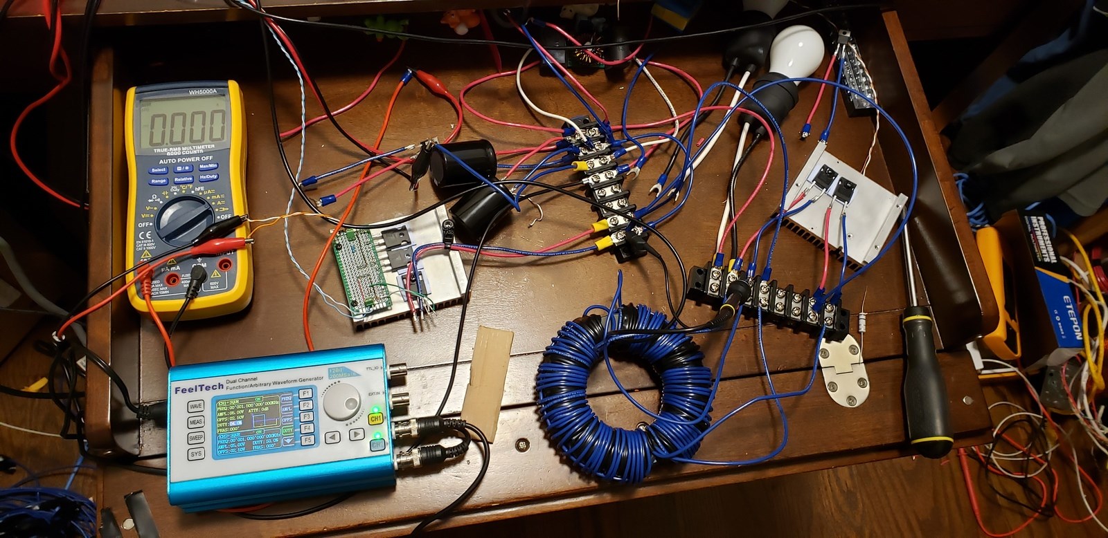
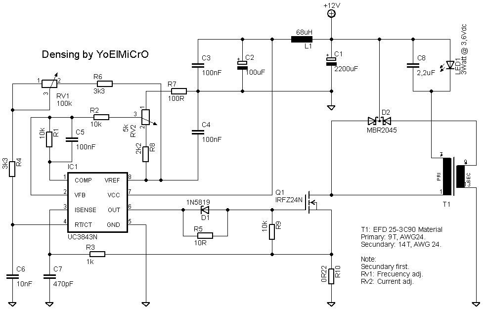
Without further ado, here is the circuit ...

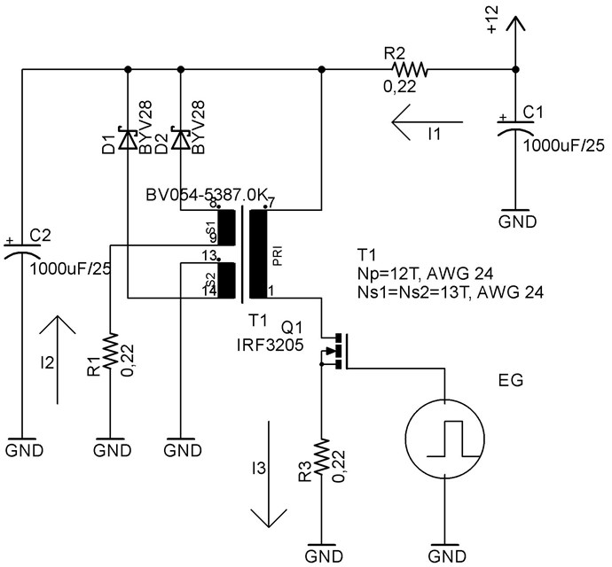
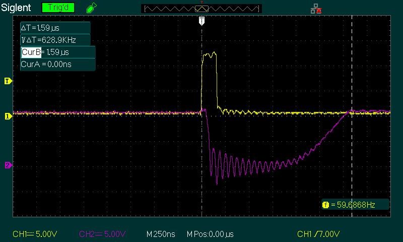
I have drawn the meaning of the currents, if we analyze we will see that I3 = I1 + I2,
an inexplicable phenomenon, but let's continue.
The core is an EFD25 material 3C90, but it can have any geometrical shape and can
calculate the turns of the primary respecting that it does not saturate, then in the secondary add to the voltage
induced diode voltage in forward, this is Np = (EdcTon / (BmAe), where Edc in volts, Ton
in micro seconds, Bm in teslas and Ae in square millimeters and for Ns1 = Ns2 = ((Edc + 1) Np / Edc, in this way they can use the nucleus they have on hand.
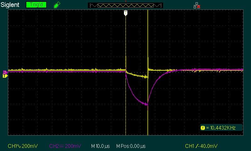
The total power absorbed from the source is ...
Pin = 0.5 (di / dt) Edc (Ton / T) which is not more than the sum of the individual absorbed powers
for the components that make up the series lasso, Pr2 + Ppt + Q1loss + Pr3.
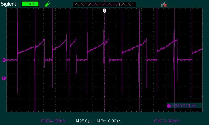
Where di / dt is the variation of current in time that crosses R2 and corresponds
only with the primary inductance, ie the magnetized inductance Ipk = (VpTon) / Lp,
the secondary S2 is responsible for returning the energy stored in the inductance
magnetizing during the period when Q1 is off and is E = 0.5Ipk ^ 2Lp, in this way
the input power is reduced to only that of the losses of the circuit and we have a 100% functional forward topology like the ones we see every day.
Now, if we connect the secondary S1 in the way we see in the circuit, we will observe the following; by having induced in the forward direction a voltage equal to that of the primary plus the
drop voltage of the serial diode the voltage that supplies the power supply will be seen
negative in the resistor R1 and the current flowing in said path will be reflected in the
primary, being I1 + I2 for the same time of Ton, the curious thing here is the following.
This current should be supplied by the power source, but it is not, that source
it only feeds the current needed to magnetize the nucleus and S2 becomes a source
more food, this should extract its energy from the environment that surrounds us and what
shows by the temperature difference in the core.
On the other hand, the output power that we take in R3 is 0.5 (di / dt) ^ 2R3 (Ton / T), being the
new di / dt the slope for a Lp much smaller than the initial one, the lower the Lp
higher output power and is tightly bound to the ferromagnetic material that the shape,
specifically with the variation in its permeability.


Excuse me for my English.

YoElMiCrO.

Order By: Standard | Newest | Votes
YoElMiCrO posted this 23 April 2019

Hi all...
Aloha, that circuit obeys the phenomenon observed in the
Fordward topology, now called by my (NLCC) No Loss Clamp Circuit.
The duration of work without feeding is due to the fact that only
consumes an infima part of the supply source (I1)
in this case the energy stored in the three input capacitors,
but there is another energy comes from the own core (I2) of the secondary side,
in this case it is better to put the serial charge to the primary and remove turns to it.

YoElMiCrO

  • Liked by
  • Chris
  • Jagau
alohalaoha posted this 10 April 2019

Self oscillating circuit at partnered topology, made by Russian guy alias "Osbourne". What is extremely interesting, this circuit has self oscillating behaviour, several minutes after power was turned off. Marking Л is CCW winding, while П is CW winding. Colored structure is Ether form buily by two partnered coils. Center toroidal vortex is vector magnetic field, while two blobs are scalar magnetic field of opposite sign. One is relative minus, other plus, or precise, one has righ hand spin, other left hand spin. Leading blob has left chirality. These data are results of preliminary Ether research of opposite coil configuration, known from Chris Sykes terminology as "partnered coils". Next experiments with barium ferrite, with 3 orthogonal coils. One is in same config as shown on pic, other is input for steady B field, and 3rd for output. Output could be again in partnered, or tesla bifilar, or caduceus conf, or combination of them. Very promising configuration for Ether's power extraction.  

Cxema:

Tuned parameters were:

Frequency = 1500 Hz, Skvaznost = 4% {or reciprocial of Duty cycle; S= T/ τau or S = 1/D.D=25}.

All diodes schottky, 3 capacitors 1600uF/25V, infineon mosfet transistor with turn off delay 15nS, two partnered coils 23mH each, ferrite data on pic.

Author continue work. His goal is house heating system for cold Russian winters.

Reg.

Aloha

  • Liked by
  • Vidura
mich posted this 10 April 2019

Hi! YoElMiCrO  if I understand correctly, varying the frequency of the pulses do you get only with certain frequencies completely different waveforms? perhaps the harmonycs of 600HZ? good day

  • Liked by
  • Vidura
  • Chris
YoElMiCrO posted this 09 April 2019

Hi all.
I have made several experiments.
I think it's already clear how to do to self-feed.
As soon as I have a little time I try the theory.
But yes, it is necessary to have at least two frequencies.
YoElMiCrO

YoElMiCrO posted this 04 April 2019

Hi, I've been through a lot of work lately.
I'll be back with new experiments.
I will read the last post to be up to date and so watch the trends.
YoElMiCrO

alohalaoha posted this 17 February 2019

Main goal is to catch anomaly voltage boost effect.

The most easiest way to do it is using next configuration.

Why should use simple when you could make it complex !

  • Liked by
  • Chris
YoElMiCrO posted this 17 February 2019

Hi all.
Today I have been doing analysis and testing
to determine whether or not there is energy gain.
I have tested the method described by N.E. Zaev and yes is right, as soon as I finish trying the circuit.
I post it to check the observed.
Look at this oscillogram ...

The yellow trace is the pulse of the Mosfet Gate.
The purple trace is the one observed in his Drain.
If you look well, you will see that time expands.


  • Liked by
  • Jagau
  • Chris
YoElMiCrO posted this 16 February 2019

Hi all.
Atti, I know that method.
Thank you for mentioning it.
Jagau, channel 2 is measuring the current in the primary, exactly at the junction of the sourse of the mosfet and R10, at that point
the magnetizing current plus the reflected current of the secondary (i3), that is the sum of (i1 + i2).


Chris posted this 16 February 2019

@Atti,

Nice example! Another example is A Novel Transformer with Compensating Coil


I Quote:

The inducted voltage in coil B must be larger than that of coil C, otherwise the transformer will require more input power than the output power.

Ref: Xiaodong Liu, Qichang Liang, Yu Liang - Department of Nuclear Physics, China Institute of Atomic Energy.


The pdf is attached.

   Chris

Attached Files

  • Liked by
  • Vidura
Atti posted this 16 February 2019

Greetings. Excuse me if you know, but I find it interesting. Maybe you have to keep in mind your theory to see if it comes to something else. Excuse me once again if you already know. https://www.semanticscholar.org/paper/Integrated-magnetics-for-current-doubler-rectifiers-Sun-Webb/aaf51cdc13e06e32b20e04263a00674855d2f4b2

  • Liked by
  • Vidura
  • Chris
Jagau posted this 13 February 2019

Thank you Yo

This is well channel 2 at output?

Jagau

  • Liked by
  • Chris
Chris posted this 13 February 2019

Hey YoElMiCrO,

I thought that might be the case. Thanks for pointing me in the right direction!

   Chris 

  • Liked by
  • Jagau
YoElMiCrO posted this 13 February 2019

Here it is, jagau.

Chris, that saw tooth is inverted, if that were the case, it would refer to a negative inductor.
In the case of my image, it is the primary current.

  • Liked by
  • Chris
  • Jagau
Jagau posted this 13 February 2019

Very interesting
Could you show me a picture closer to your oscilloscope, if you do not mind?
thank you YoEIiCRo


Jagau

  • Liked by
  • Chris
YoElMiCrO posted this 13 February 2019

Hi all
jagau, it's a single oscillator.
Just as it is in current, when you adjust the frequency
a second frequency appears, that is normal because
the current in the primary takes more time than the period of
oscillation.

  • Liked by
  • Chris
  • Jagau
Jagau posted this 13 February 2019

Hy Yo


your scope look like have 2 beat frequency with 2 high peak, like Akula?


Jagau

  • Liked by
  • Chris
Chris posted this 12 February 2019

Nice Work YoElMiCrO!

I may be interpreting the Scope incorrectly, if so ignore my post:

Perhaps the Coils may have the wrong polarity? The Sawtooth waveform is should look like this:


Very nice build! Thanks for sharing!

   Chris

YoElMiCrO posted this 12 February 2019

Hi all
I believe that the correct path is the one proposed by N.E Zaev.
From what I've been seeing, it's the method he uses
Akula.
alohalaoha, I comment ...
Any method in which they use high voltage, refers to the behavior of an inductor.
I will try to explain from my point of view its operation in another post, because it is extensive.
I will also try to explain the observed magnetic phenomenon
in the fordward topology. This refers to Floyd Sweet.

Jagau posted this 11 February 2019

hi aloha


The schematic that you proposed is difficult to read and confused.
Is it Melnichenko basic circuit?


Jagau

  • Liked by
  • Chris
alohalaoha posted this 08 February 2019

Hey Yo

Rearrange your circuit according this sch.

You will get what are you looking for even without ferrite core. It mean effect is not due to core properties, but to complex coil/ambient geometry. Both inductances not mandatory need be the same, asymmetric configuration is prefereble.

Our task is to find optimal asymmetric ratio for anomaly energy boost. All the other is just a matter of techniques.

As one of greatest Russian physicist Petr Leonidovitch Kapica had said many years ago:

"The real science is not what is possible - but what is imposible! What is possible is just a current technology".

Jagau posted this 07 February 2019

I understand now

we are not looking for same thing, thanks for pecision

Jagau

  • Liked by
  • Chris
  • Vidura
YoElMiCrO posted this 07 February 2019

hi Jagau
if you look at the oscillogram you will see that it obeys the same phenomenon, I comment that it is not self-powered, first observe AU and then try to self-feed.

Thank you very much.

  • Liked by
  • Chris
  • Vidura
Jagau posted this 07 February 2019

 Do you think that the schottky barriery rectify cancell the effect of P.O.C.

I do not think you will find the same effect.

It is Just an observation YO

Anyway it's your circuit it's up to you to decide,

Jagau

  • Liked by
  • Chris
  • Vidura
YoElMiCrO posted this 07 February 2019

Jagau, it's different, it just keeps the same phenomenon.
It's another way to achieve and simplify to only two
windings, if you notice you will see that the only difference is that the load is placed serial to the primary, where the current flows which is the sum of I1 + I2 and also the current of demagnetization.

  • Liked by
  • Chris
Jagau posted this 07 February 2019

Hi yo

Just to make sure I understood correctly, the circuit proposed at the beginning is not the same as you now propose,

it is completely different ??

Jagau

  • Liked by
  • Chris
  • Vidura
Chris posted this 07 February 2019

Awesome work and verification YoElMiCrO!

May I ask, have you read my thread: Some Coils Buck and some Coils DONT

There is a lot of information in there that you may be able to align with your work. Ideally a system with TOn < 10% & TOff > 90% when TOff is the work Cycle of the Bucking Coils, can be ideal.

The Voltage drop issue can be resolved with Timing, invoking a Transient, getting this to occur:


Ref: https://www.youtube.com /watch?v=EUXOZAinUPk


Or by playing around with Turns or both.

   Chris

YoElMiCrO posted this 07 February 2019

Hi all.

I have already done tests.
Yes !, Chris is right when he says that this phenomenon obeys the experiment of
current made by Mr Preva, only that in this circuit the point of operation is in the first quadrant of the hysteresis cycle, not as in the case of MrPreva which are the two quadrants of the cycle, the first and third.
The circuit in question is this ...

Let's look at this oscillogram ...

The two di / dt are appreciated, the one with the lowest slope is the one that sees the source of supply
and the one with the steepest slope is the one that circulates through the load, I1 and I3.
Analyzing the situation we observed that the inductance fell in value for the load, because
It is the same TonVdc and its slope is greater.
For this circuit to work, the primary voltage must be constant, that is, the
sum of the individual tensions will be the supply.
In this circuit, the output voltage will always be lower than the supply voltage, as
a Buck converter would do it, however the relation VdcTon / T = Vout does not apply and its point of operation will be at the discontinuous / continuous boundary.
For this particular case the LED is ~3.6V@830mA and the 12Vdc supply source,
as the average current of the led is 0.83A, the peak current should be 2 * 0.83 = 1.66A and we will adjust Rv2 until the voltage in resistor R10 has a greater peak equal to 365mV in the ramp, the frequency should be more low while adjusting this current, note that this current is the sum of the two individual I1 and I2.
Then we can adjust Rv1 to finally set the point of operation in the border continuously, if necessary we can change C6, to readjust Rv1 again.
The calculation of the transformer is as follows ...
Edc = Vled + Vp + Vsat + Vr10, if we ignore the voltage drops Vsat + Vr10 we will remain
that Vp = Edc-Vled and we can calculate the number of turns for the primary.
Suppose FSw = 55KHz, Ae = 58mm², Bm = 0.25T and Ton = 85% T = 0.85 * 18uS = 15uS.
These data are for the EFD25 that you use, this saturates ~ 0.330T and we will have to be
below this value, also how it works on a fordward basis should not have a gap
the core used.
We calculate then ...
Np = VpTon / (BmAe) = (12-3.6) * 15 / (0.25 * 58) = 8.6 ~ 9Turns for the primary.
As the voltage that is induced in the secondary must be Edc + Vfd, then ...
Ns = VsNp / Vp = (12 + 1) * 9 / (12-3.6) = 13.9 ~ 14Turns for the secondary.
And these will be the data of the transformer, as they see the energy stored in the
primary is also added to the load during the demagnetization cycle through
of the half of the diode D2, not being so in the circuit proposed above.

If you have any questions, let me know.
We are in touch.

  • Liked by
  • Chris
  • Vidura
YoElMiCrO posted this 05 February 2019

Hi all.
Today I get the 3 Watt LED.
I will begin the tests as soon as I have it in hand,
for this circuit the load must be of constant tension.
I will talk about progress.

Thanks Chris and everyone.

Chris posted this 01 February 2019

Very nice YoElMiCrO!

Looking forward to some results.

   Chris

  • Liked by
  • cd_sharp
YoElMiCrO posted this 01 February 2019

Hi all.
Here some images of the circuit assembled.
I still do not have the 3W led, when I do
tests post oscillograms and powers.

Chris posted this 31 January 2019

Hi YoElMiCrO,

Your English is perfectly understandable, it is good wink

I agree, working together we can improve these Systems! I must say, it is important that they are understood, the basic layout and how they work must be understood first. Approaching these Systems with no understanding almost always ends in failure.

   Chris

  • Liked by
  • Zanzal
YoElMiCrO posted this 31 January 2019

Hi all.

Apologize, I have not had much time.
As soon as you have a working prototype
I raise diagram and catches of the oscilloscope.
This is based on a buck converter that also
it works in fordward, but it has already added the PWM
of control and we can improve it among all.


Again, excuse my English.


Cd_sharp, upload pictures of the physical circuit.
Chris, when you see a grammatical error, you certainly fix it.
Thank you very much.

Chris posted this 30 January 2019

Hey Zanzal,

I think you have a lot more experience, so your existing experience gives you the knowledge to be able to make changes as you see fit.

I am still learning today, when I make changes to my machines, sometimes its for the worse, sometimes for the better...

I do however urge those learning to replicate as close as possible to the original, you will benefit from following the outlined Circuit much more if you approach it this way! I promise you!

   Chris

  • Liked by
  • Zanzal
  • Aetherholic
Zanzal posted this 30 January 2019

Yes, I agree Chris, sticking with the circuit as presented will be the best course. Part of what I am seeing my replication and the path that led me to the changes was something I introduced into the circuit unwittingly. Is it good, is it bad, time will tell, I need to study it more, but I also need to fix it and go back to the original. Perhaps I should have made my own thread in hindsight.

Chris posted this 30 January 2019

My Friends,

The basic Circuit layout is simple:


I suggest replicating the very simple circuit with the recommended values, turns and so on. Learn how this circuit may work. Learn what is being presented. Learn how to optimise this circuit before changing it. Truly an hours work could see a nice replication.

Changing the Circuit that's presented is not a wise approach, when learning the ideas presented.

   Chris

Atti posted this 30 January 2019

Can be replaced according to the two drawings above: S1-T, S2-VCS. VT is the control coil.  The VT coil is twice the coil T. So there is a noticeable similarity in other works. It is also worth using performance measurement for a better understanding.

  • Liked by
  • Zanzal
  • Chris
Chris posted this 30 January 2019

Thanks for sharing Zanzal!

S1 and S2 must have sufficient interactions, both equal and opposite for Current, Voltage is not the case, same as The Mr Preva Experiment.

I tend to agree, we are not yet at the stage where running machines would benefit the community, we don't have sufficient momentum yet. It would just create division, as some do not yet have sufficient knowledge of what we are doing!

   Chris

  • Liked by
  • Atti
  • Zanzal
Zanzal posted this 30 January 2019

Some additional observations from my own replication:

  • L3 was not contributing significantly to the output so these observations are based on using only two coils.
  • High side switching is not required, low side seems to work just fine.
  • The following turn ratios did not yield good results: 12 to 108, 108 to 108, 12 to 36.
  • Increasing the capacitance of C1 to 22mF didn't harm the operation in anyway, though charging was slower, energy stored over time is greater.
  • The gap remains important, efficiency is harmed very easily in my setup because the gap is hard to get right.
  • Duty cycle and frequency do not need to be spot on. With lower capacitance it is easy to find the perfect frequency and duty cycle to maximize output.

So most important factors for my setup is: gap and turns. Since previous experiments helped me to understand how this particular core needs to be gapped to get the most out of it, it would largely be a matter of finding the best turns ratio. Also finding the best mosfet and diodes still needs to be done, that could give me a little bit more efficiency, but I don't expect huge gains there.

Note: In both of the above the signal generator is still directly connected to the mosfet gate and ground so this replication is not self-powered. I don't plan to share any self powered results though if someone else wishes too, that is certainly their choice.

  • Liked by
  • Chris
  • Atti
Zanzal posted this 30 January 2019

Circuit seems like a good start to me. The only change I made was to switch it high side and use Chris' recommended winding ratio. My no-load replication self-sustains with only signal generator input and some initial cap charging. Also I ditched C2 and just went with a bigger C1. Not getting massive output, but its plausibly AU without the signal generator.

With an initial charge of 4V the C1 (a 2200uF cap) charged slowly to 30.39V. Duty cycle was 9.695% at 27.638kHz. The transformer had two 108 turn secondaries with a 36 turn primary. The two halves of the core were specially gapped. Thanks YoElMiCrO for sharing your circuit.

Atti posted this 29 January 2019

It is really worth examining this topology. I have already mentioned, but I'll take it again. Árpád Bóday's invention. 


https://patents.google.com/patent/CA2172240A1/en

http://patents.ic.gc.ca/opic-cipo/cpd/eng/patent/2172240/summary.html

  • Liked by
  • Chris
  • Vidura
Chris posted this 28 January 2019

Please forgive me if I have renamed incorrectly, I have done so to increase awareness.

About unity in forward topology?


to

Above unity in forward topology?


   Chris

  • Liked by
  • Vidura
  • Aetherholic
Chris posted this 28 January 2019

My Friends,

@CD, agree and yes this is very familiar - The simplicity is beyond comprehension! YoElMiCrO knows his stuff, is experienced in the arts!

This is a very simple Experiment! It follows all the rules we are already familiar with. We see: R1 ( 0.22 Ohms ) is a Conduction Delay for the Diode: D2. We see a step up, 12 turns to 13 turns. We see Currents Oppose, depicted by the Arrows! We see Two Output Coils, Partnered Output Coils! We see much more of what we have already covered!

Everything about this follows the same rules we have outlined on this Forum!

I would encourage others to replicate and share their experiments!

   Chris

cd_sharp posted this 28 January 2019

Hey, @YoElMiCrO,

what a fantastic post! This looks a lot like some of Akula's work. I would be very glad to see the practical experiment you are talking about.

"It's just the knowledge of the coils and how they interact with each other" (Stephen Mark)

Chris posted this 25 January 2019

Hey YoElMiCrO,

An excellent post! Very well presented and thought out!

You very clearly are following the same path we are on - The erroneous "Generation" of E.M.F resulting in Currents that are Pumped from the Near Field in the immediate area of the Magnetic Fields.

Any Source of Energy, I should say any Source of Imbalance, of Equilibrium, is a Source of the Poynting Vector. Near Field interactions, pumping Energy into the Immediate Space.

Coils are Antenna's!

Great Thread, please continue!

   Chris

  • Liked by
  • Vidura
  • Aetherholic
We're Light Years Ahead!
Members Online:

No one online at the moment


What is a Scalar:

In physics, scalars are physical quantities that are unaffected by changes to a vector space basis. Scalars are often accompanied by units of measurement, as in "10 cm". Examples of scalar quantities are mass, distance, charge, volume, time, speed, and the magnitude of physical vectors in general.

You need to forget the Non-Sense that some spout with out knowing the actual Definition of the word Scalar! Some people talk absolute Bull Sh*t!

The pressure P in the formula P = pgh, pgh is a scalar that tells you the amount of this squashing force per unit area in a fluid.

A Scalar, having both direction and magnitude, can be anything! The Magnetic Field, a Charge moving, yet some Numb Nuts think it means Magic Science!

Message from God:

Hello my children. This is Yahweh, the one true Lord. You have found creation's secret. Now share it peacefully with the world.

Ref: Message from God written inside the Human Genome

God be in my head, and in my thinking.

God be in my eyes, and in my looking.

God be in my mouth, and in my speaking.

Oh, God be in my heart, and in my understanding.

Your Support:

More than anything else, your contributions to this forum are most important! We are trying to actively get all visitors involved, but we do only have a few main contributors, which are very much appreciated! If you would like to see more pages with more detailed experiments and answers, perhaps a contribution of another type maybe possible:

PayPal De-Platformed me!

They REFUSE to tell me why!

We now use Wise!

Donate
Use E-Mail: Chris at aboveunity.com

The content I am sharing is not only unique, but is changing the world as we know it! Please Support Us!

Thank You So Much!

Weeks High Earners:
The great Nikola Tesla:

Ere many generations pass, our machinery will be driven by a power obtainable at any point of the universe. This idea is not novel. Men have been led to it long ago by instinct or reason. It has been expressed in many ways, and in many places, in the history of old and new. We find it in the delightful myth of Antheus, who drives power from the earth; we find it among the subtle speculations of one of your splendid mathematicians, and in many hints and statements of thinkers of the present time. Throughout space there is energy. Is this energy static or kinetic? If static, our hopes are in vain; if kinetic - and this we know it is for certain - then it is a mere question of time when men will succeed in attaching their machinery to the very wheelwork of nature.

Experiments With Alternate Currents Of High Potential And High Frequency (February 1892).

Close