Can we measure magnetic flux with an oszilloscope?

  • 1.2K Views
  • Last Post 28 July 2020
baerndorfer posted this 06 July 2020

While playing around with the oszilloscope i found the thing called 'Cycle Area' in the measurement section. It give me a reading in Voltseconds [Vs].

i did a bit of research (means i follow Chris posts) and found out that...

We can calculate flux from the time integral of the voltage V on a winding.

Φ = (1/N)V.dt   webers

This is one form of Faraday's law. If a constant voltage is applied for a time T then this boils down to..

Φ = V × T / N  Wb

Because of this relationship flux is sometimes specified as volt seconds.

source: http://info.ee.surrey.ac.uk/Workshop/advice/coils/terms.html  
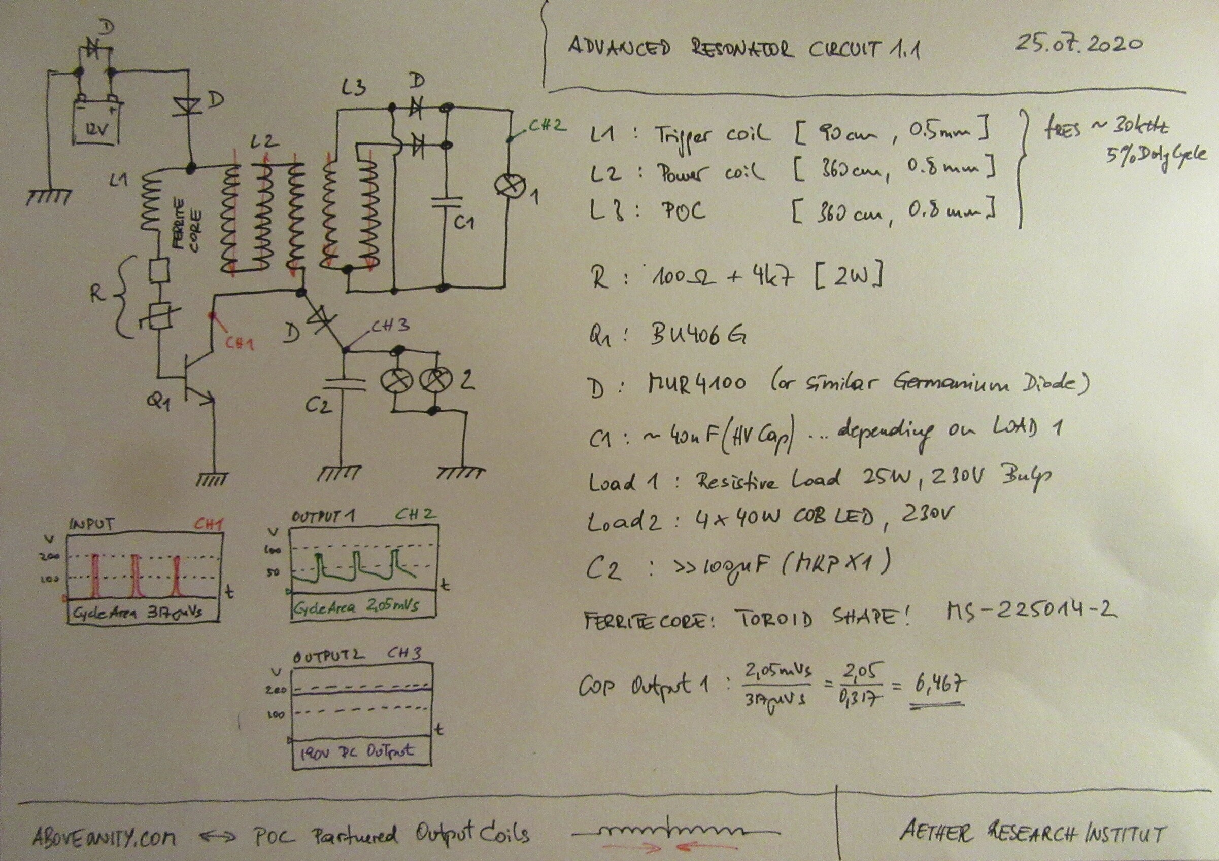
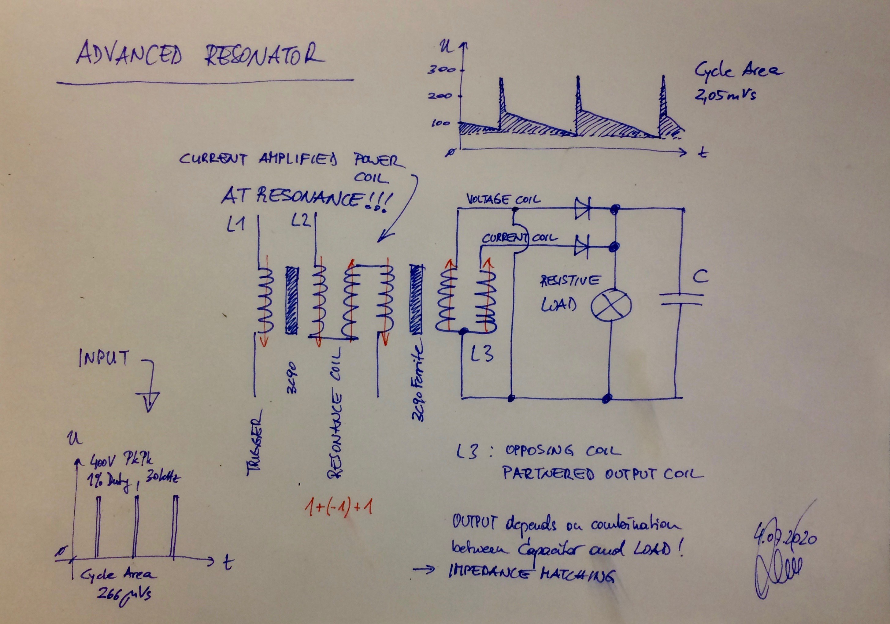
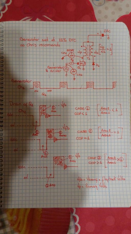
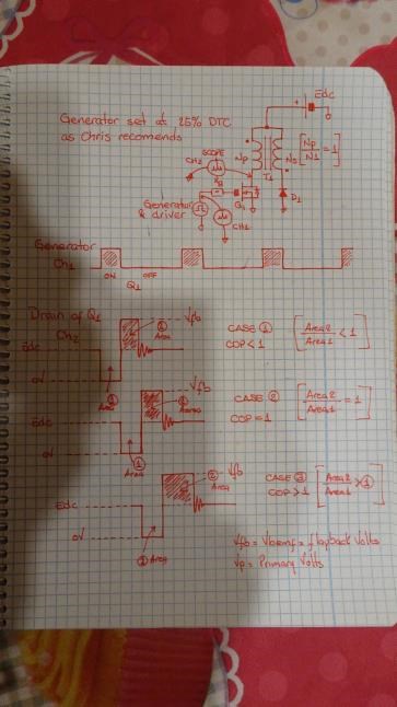
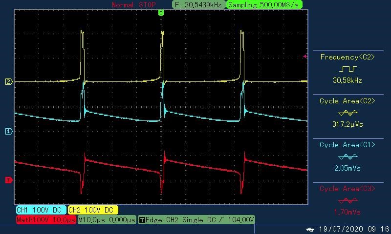
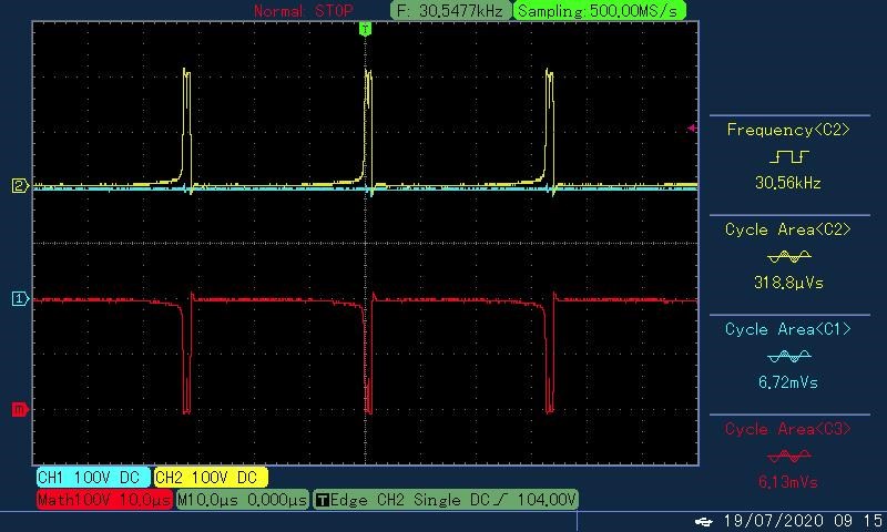
 

now here is a scope-shot..    

I have 2 cycle areas and when i compare both areas then there is a difference between them. if i say for example that the yellow area is representing the amount of energy that is given to an aparatus and the blue area is the amount of output - can i calculate the COP factor based on these values?

regards!

Order By: Standard | Newest | Votes
baerndorfer posted this 25 July 2020

Hi all,

this is the circuit if someone like to replicate.

YoElMiCrO posted this 06 July 2020

@ baerndofer.

Yes, of course.
If we use the law of conservation of energy
within magnetism this relationship must be fulfilled.
VpTon = (Vbemf-Vp) Toff
If we now apply thermodynamics then it tells us that ...
VpTon> (Vbemf-Vp) Toff in the real world and in ideal
they will be the same.
If the second member's volts-second are greater
than the first, then COP> 1.
I don't know if it helps you.

Thank you all in advance.

YoElMiCrO.

Chris posted this 06 July 2020

Thanks YoElMiCrO!

This is a little out of my skill level, I know about it, but not inside out, Thank You for explaining!

So mathematically, converting to smallest Units ( Micro ): 2050 / 266.0 = 7.70676691, so COP = 7.70676691.

Of course, looking at the scope shots, the Yellow Trace is the Input and the Blue Trace is the Output, so we have a situation where we see COP = 7.70676691.

Baerndofer, you should be very proud, Well Done My Friend!

Humanity has a chance, all they need do is take it with a grasp like their future depends on it!

Best wishes, stay safe and well My Friend,

   Chris

YoElMiCrO posted this 07 July 2020

Hi all.

@Chris
Let's dig a little deeper into this topic.

The reference point to calculate the cop depends on the topology
in question, but they will always be taken within the same frame of reference.
I explain...

For example…
In a flyback topology, we measure the mosfet drain that
works as sw on the primary side.
As this type of topology does not open any reflected current
during the Ton cycle from secondary to primary, because the
the secondary diode is in the open state.
Having said that, let's continue ...
Let's imagine that the two windings have the same number of turns,
this as we all know is Np / Ns = 1.
Imagine an ideal mosfet that turns on 20uS and that the power supply
It is 12Vdc.
This means that the primary winding will have 12Vdc applied for 20uS,
this is 12 * 20 = 240V / uS for the Ton area.
Let's see what happens inside the Toff area ...
When the mosfet is turned off, the inductor will change polarity in the
I try to keep the current flowing in the same direction, this causes
the diode on the secondary side (also ideal) starts driving.
Since in this topology the secondary voltage depends on the load, let's imagine
that the load resistance is such that the secondary voltage is the same
than the primary one.
If we look at the mosfet drain tension on the primary side we will see
which now has twice the source voltage for another 20uS.
This indicates that COP = 1, since [(Vbemf-Vp) Toff] / (VpTon) = [(24-12) 20] / (12 * 20) = 1.
So…
For a COP> 1 we need the first term of equation be greater than the second.
This would happen for example if ...
There is twice the primary voltage for a longer time than Ton,
say 25uS or if the voltage at the mosfet drain is greater than two Vdc during
the same time.
I think it is clearer how to calculate COP by looking at the two areas they take
the two times within the duty cycle.

This topic is a little difficult to understand, but not impossible.

Note:
In order to calculate the cop of the baerndofer circuit we need
all available data.

Thank you all in advance.

YoElMiCrO.

Chris posted this 07 July 2020

Thank You YoElMiCrO,

You are very wise, thanks for explaining and correcting me! I very much appreciate your wisdom helping us! As do all others here also!

I think, saying, what we are doing is no different from Don Smith's work really, its pretty much the same, I knew about Don Smith in the early days but did not study his work till only about 6 years ago, I was stunned to see the parallels!

I again would like to acknowledge those before me! They were Giants!

Best wishes, stay safe and well My Friend,

   Chris

baerndorfer posted this 12 July 2020


If we use the law of conservation of energy
within magnetism this relationship must be fulfilled.
VpTon = (Vbemf-Vp) Toff
If we now apply thermodynamics then it tells us that ...
VpTon> (Vbemf-Vp) Toff in the real world and in ideal
they will be the same.
If the second member's volts-second are greater
than the first, then COP> 1.
I don't know if it helps you.

YoElMiCrO.

This helps a lot thank you.

But i have to find a place where i can study what Vbemf or Vp is in detail. I'm always struggling with these shortcuts because there are different explanations and different wordings out there. At last english is not my language at all....

Again thx everyone for helping each other - this is the way to go.


I think it is clearer how to calculate COP by looking at the two areas they take the two times within the duty cycle. YoElMiCrO

Oh yes, this is what i like! thx!

I like to show a drawing that i did while studying this POC thing..

It helps me to get a basic understanding - maybe you find it useful too.

regards!

YoElMiCrO posted this 14 July 2020

Hello baerndofer.

I hope this is better.

Thank you all.

YoElMiCrO.

YoElMiCrO posted this 13 July 2020

Hi all.

@baerndofer.

Vp is the voltage seen by the primary winding during the time of Ton,
this is generally the source voltage, as long as the drop in
voltage at the power switch is negligible compared
with that of the supply source.
Vbemf or flayback voltage (Vfb) is the voltage that appears just after
that we turn off the power switch.
Looking at this image is better understood ...

If we analyze we will see that the energy that we extract from the source of
feeding only occurs within the Ton cycle, since in the winding
secondary no current flows, (the diode is in reverse) due to
that all the starts in the transformer are positive.
In this way only the primary magnetizing inductance will remain, it is in this
inductance where we store in magnetic form the energy that
we extracted from the power supply during Ton.
However…
During the Toff cycle, polarity will change in all windings
transformer, as there is no current flowing through the primary and
polarity being reversed, the diode on the secondary side conducts,
setting the voltage to (Edc + Vfd), the source voltage plus the conduction voltage
of the diode, being a transformer, the voltage from the secondary to the primary is now reflected
but in the opposite direction, this causes this voltage to add to that of the power supply.
Since the ratio of this example is 1: 1 the primary side flayback voltage will be
Edc + (Edc + Vfd) = 2Edc + Vfd, if Vfd = 0, I mean an ideal diode then we will see
that the voltage that appears in the mosfet drain is twice the supply voltage.
For the COP in this example to be greater than unity, we need the time
where Toff's tension appears to be greater than Ton's.

Thus COP can be measured using the two areas calculated in volts seconds.

Thank you in advance.

YoElMiCrO.

baerndorfer posted this 14 July 2020

ok first of all i do the switching with a transistor and look at the Collector which gave me the yellow curve (cycleArea). the oszilloscope GND is connected to Minus (-) from source. what i do not have is a measurement of the current which is flowing through the Base of the Transistor. I have to add this amount of energy to get a correct calculation.

@YoElMiCrO: Beautiful drawing!!! Maybe you can re-upload it with a higher image quality? I have problems reading your paper.

@Chris: you're great

baerndorfer posted this 19 July 2020

in the first image you can see the energy which is given to the system (yellow[2]). the output from POC is the blue[1] signal and the scope is measuring the difference (red[m]).

it turns out, that there is more than one point for extracting energy.

the next image is from the same setup - i only changed the probe to the second extraction point.

measured under load..

no more words needed...

Chris posted this 19 July 2020

Hey Baerndorfer,

Thank You for sharing!

I have seen the scope shots you show in my work, and want to say this is real and achievable very easily! It only takes a little work!

It should be noted, other works also show similar waveforms, The MEG from the Tom Bearden Team and they reported up to 100 times the input.

Rest assured, these machines work as we have been sharing and Baerndorfer is sharing excellent work here that others should take notice of. Above-Unity Members are making Real World Progress and My Members should be taken seriously! We are very Scientific in our approach and we have shown progress decades in advance of other forums or persons out there!

My Members are the most awesome Team you will ever meet! They have already made History!

Be part of something better!

Best wishes, stay safe and well,

   Chris

Chris posted this 20 July 2020

Hi baerndorfer, Interesting, why there is DC output on the poc in the second scope shot. Vidura.


Hi Vidura,

The same waveforms was shown in my video, particularly Video Seven. The DC comes from the Potential Difference between the Coils. The Coils Holding the Potential High, Bucking, Partnered Output Coils:


for an extended time period. This is the same effect as dropping the Neo Magnet down a Copper Tube:


Why does the Magnet take so long to fall down the Tube? Why does the Magnet Defy Gravity? We all know why, its pretty simple! The greater the Potential gained, the greater the output, there is no limit! You can create a machine that potentially could melt the copper wire to the output if you had enough experience in building these machines!

Baerndorfer has done an excellent job replicating these effects! He has a very nice, smooth running machine!

Best wishes, stay safe and well My Friends,

   Chris

Chris posted this 14 July 2020

You guys are awesome!

Yes 25% or less is about where you want to be, in my video series, I used 10% Duty Cycle. This is a parameter you can experiment with, to find the best result.

Best wishes, stay safe and well My Friends,

   Chris

Vidura posted this 20 July 2020

Hi baerndorfer, Interesting, why there is DC output on the poc in the second scope shot. Vidura.

baerndorfer posted this 20 July 2020

i cannot answer that vidura. what i can see is, that there is a pulse going into a diode. and after the diode there is pure DC.

Chris posted this 14 July 2020

@Baerndorfer,

I believe you are on the right track with your original post! I believe, and please correct me if I have misunderstood, that YoElMiCrO is saying, we dont have your data on measurements, but that you are right in your approach.

If we have a circuit, and this circuit is in YoElMiCrO's Flyback configuration:


Then I believe YoElMiCrO is saying we have to be careful with the Voltage we measure on the Drain, as the area will generally not be the correct readable used value.

However, if we swap the Switch (sw) to the High Side, then we need to measure the Source, as this is the Voltage across the Coil:


I believe YoElMiCrO is warning us about correctly measuring the Voltage Area on the Input vs the Output.

For the COP in this example to be greater than unity, we need the time where Toff's tension appears to be greater than Ton's.


Which your original Scope Shot was! We just did not know where you measured, therefore we can only guess at the measurement, which was guessed to be correctly measured and calculated to be COP > 1.

Best wishes, stay safe and well My Friends,

   Chris

Chris posted this 14 July 2020

Your'e doing a great job and we very much appreciate your sharing your work Baendorfer!

Keep up the great work!

Best wishes, stay safe and well My Friend,
Chris

Chris posted this 28 July 2020

Hey Baerndorfer,

Thank You for sharing!

Best wishes, stay safe and well My Friend,

   Chris

We're Light Years Ahead!
Members Online:

No one online at the moment


What is a Scalar:

In physics, scalars are physical quantities that are unaffected by changes to a vector space basis. Scalars are often accompanied by units of measurement, as in "10 cm". Examples of scalar quantities are mass, distance, charge, volume, time, speed, and the magnitude of physical vectors in general.

You need to forget the Non-Sense that some spout with out knowing the actual Definition of the word Scalar! Some people talk absolute Bull Sh*t!

The pressure P in the formula P = pgh, pgh is a scalar that tells you the amount of this squashing force per unit area in a fluid.

A Scalar, having both direction and magnitude, can be anything! The Magnetic Field, a Charge moving, yet some Numb Nuts think it means Magic Science!

Message from God:

Hello my children. This is Yahweh, the one true Lord. You have found creation's secret. Now share it peacefully with the world.

Ref: Message from God written inside the Human Genome

God be in my head, and in my thinking.

God be in my eyes, and in my looking.

God be in my mouth, and in my speaking.

Oh, God be in my heart, and in my understanding.

Your Support:

More than anything else, your contributions to this forum are most important! We are trying to actively get all visitors involved, but we do only have a few main contributors, which are very much appreciated! If you would like to see more pages with more detailed experiments and answers, perhaps a contribution of another type maybe possible:

PayPal De-Platformed me!

They REFUSE to tell me why!

We now use Wise!

Donate
Use E-Mail: Chris at aboveunity.com

The content I am sharing is not only unique, but is changing the world as we know it! Please Support Us!

Thank You So Much!

Weeks High Earners:
The great Nikola Tesla:

Ere many generations pass, our machinery will be driven by a power obtainable at any point of the universe. This idea is not novel. Men have been led to it long ago by instinct or reason. It has been expressed in many ways, and in many places, in the history of old and new. We find it in the delightful myth of Antheus, who drives power from the earth; we find it among the subtle speculations of one of your splendid mathematicians, and in many hints and statements of thinkers of the present time. Throughout space there is energy. Is this energy static or kinetic? If static, our hopes are in vain; if kinetic - and this we know it is for certain - then it is a mere question of time when men will succeed in attaching their machinery to the very wheelwork of nature.

Experiments With Alternate Currents Of High Potential And High Frequency (February 1892).

Close