My Friends,
For your reference: From the Measurement Thread
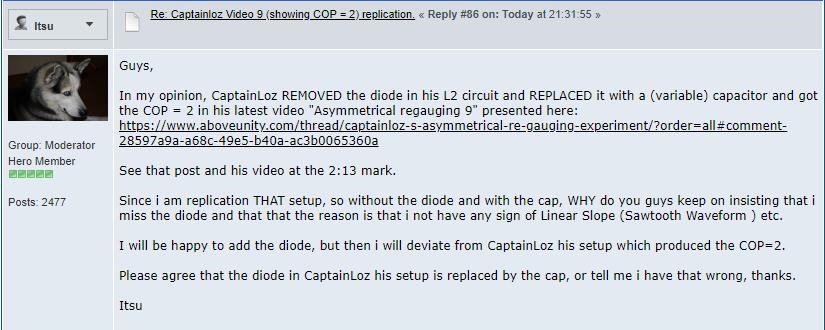
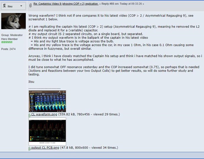
My Friends,
In our quest to bring easy simple measurement to every person with an Oscilloscope, we have had a few issues that have cropped up, simple issues to fix, but issues one needs to be aware of.
Best Practice: It is always best practice to use a Current Sensing Resistor ( CSR some use the term CVR Current Viewing Resistor ) that will have the least possible effect on the Circuit! As if the CSR was not in the Circuit! Remember, you always want to take measurement on the Circuit , which means if you change the Circuit by introducing large Impedances, the Circuit is no longer the same! To take accurate Measurements, the Circuit must be minimally affected by introducing your Measurement Equipment! This is important!
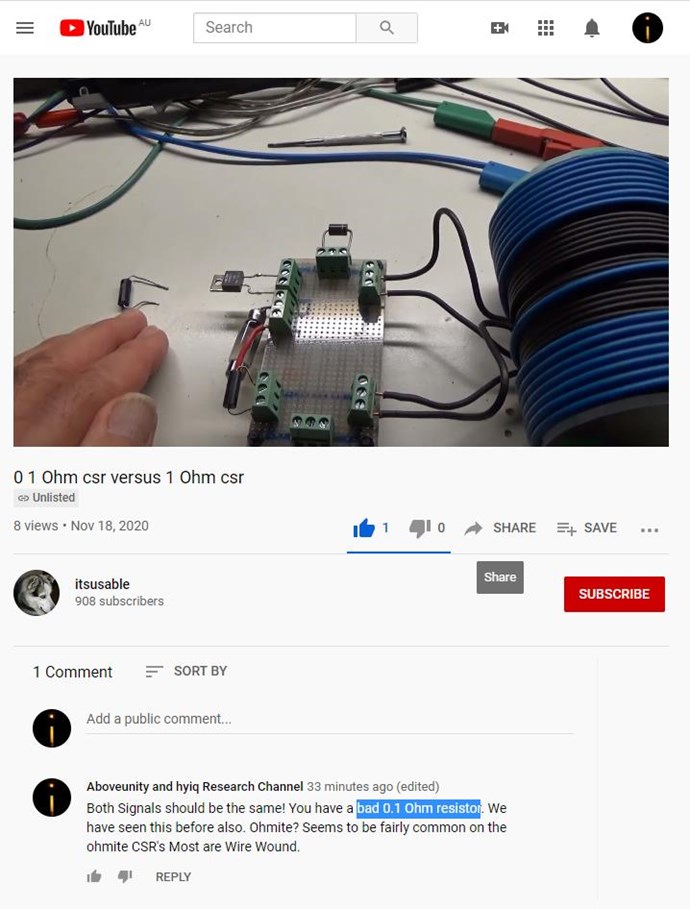
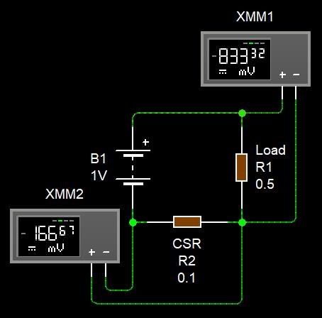
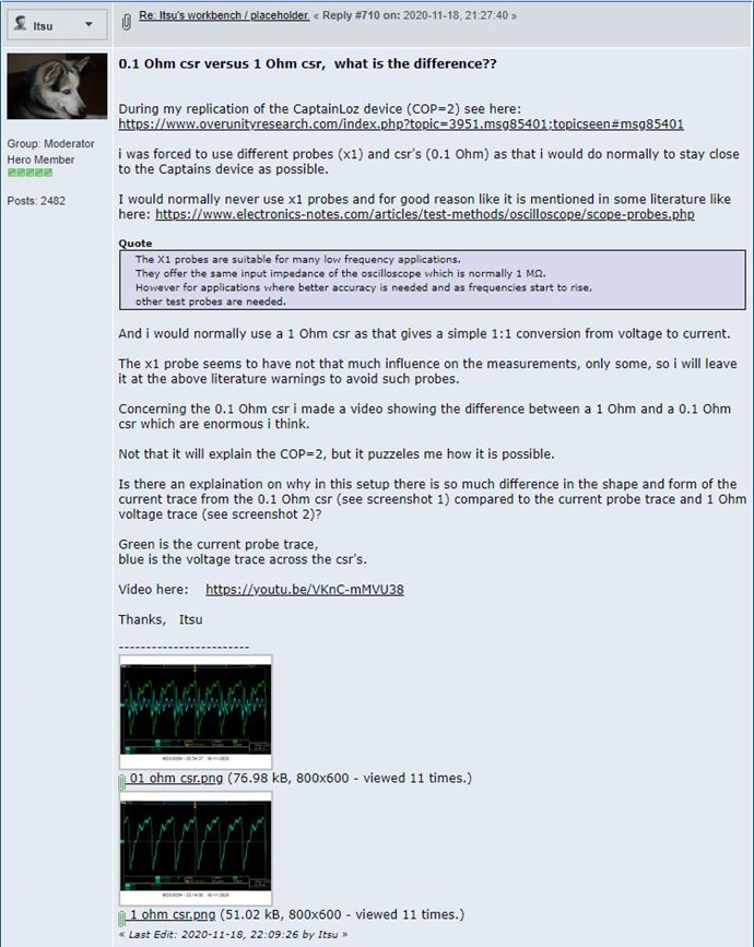
Recently, Itsu has done a video on 1 Ohm vs a 0.1 Ohm resistor:
For sure, the 0.1 Ohm Resistor is Bad!
Ohmite Resistors are commonly Wire Wound, they say that they are not, or say: "Non-Inductive" but beware, they can go bad very easily!
CD_Sharp has seen this issue before and we have resolved this simply by replacing the Resistor.
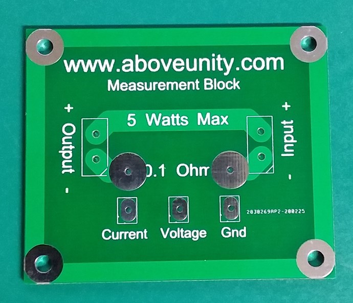
This is another reason Equipment should always be Calibrated and Checked! We have not yet seen any issues with the Measurement Block I have shared with you all! The Measurement Block should always give you a solid stable Signal! However, it is wise to Test its accuracy on a regular basis!
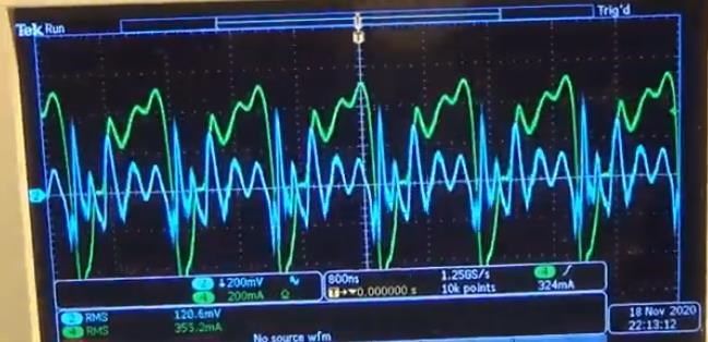
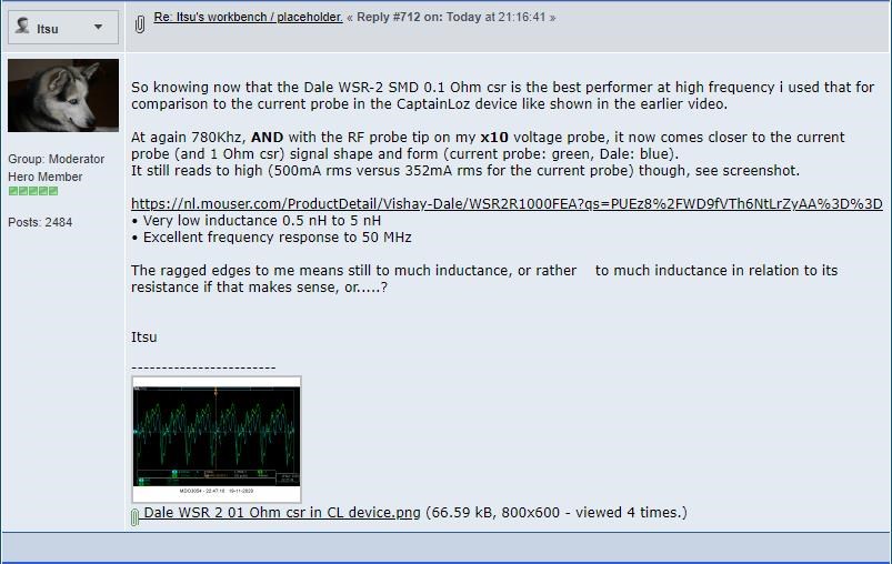
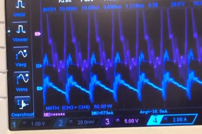
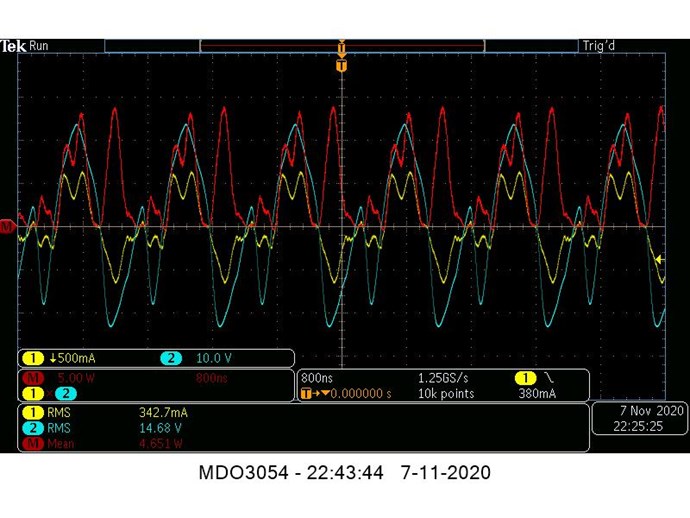
Where:
- Green Trace = Clamp on Current Probe.
- Blue Trace = 0.1 Ohm Current Sensing Resistor.
Current Signals should always be the same! If they are not, as in Itsu's case, above image, there is a Problem!
I have left a Message:
Best Wishes
Chris
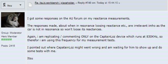
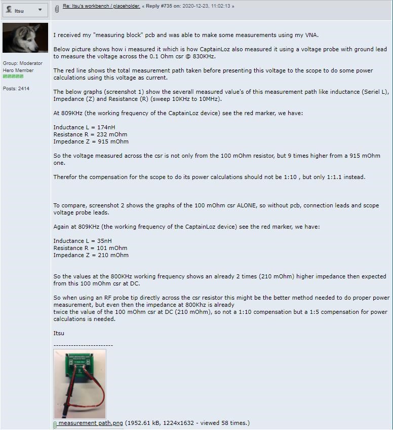
Itsu has a fresh round of "Surprising" data:
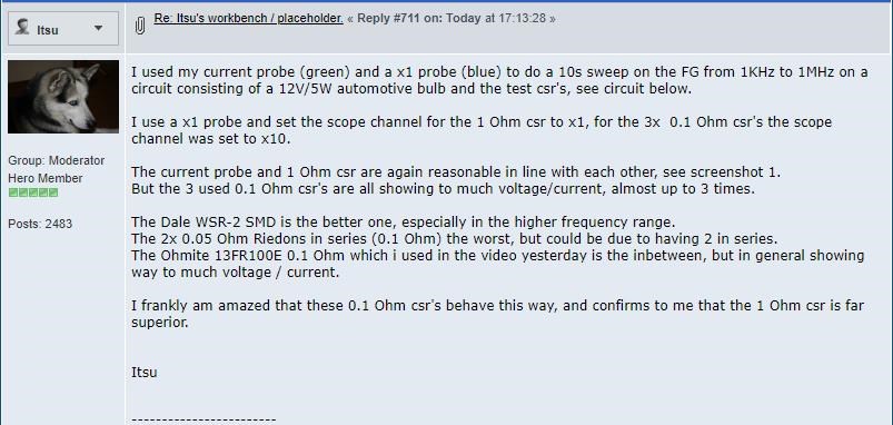
Ref: Itsu's workbench / placeholder.
This is an astounding series of statements! It really is!
Every single Engineer on the planet will disagree with Itsu's statement that a 1 Ohm Current Sensing Resistor is Superior!
Proving Incorrect
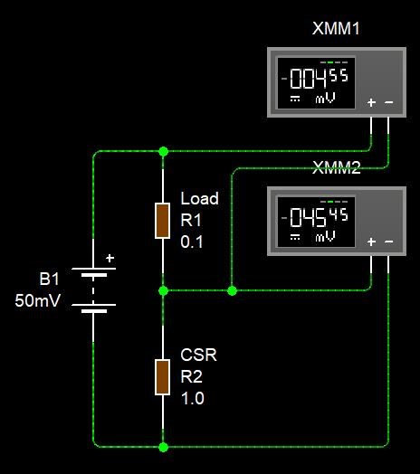
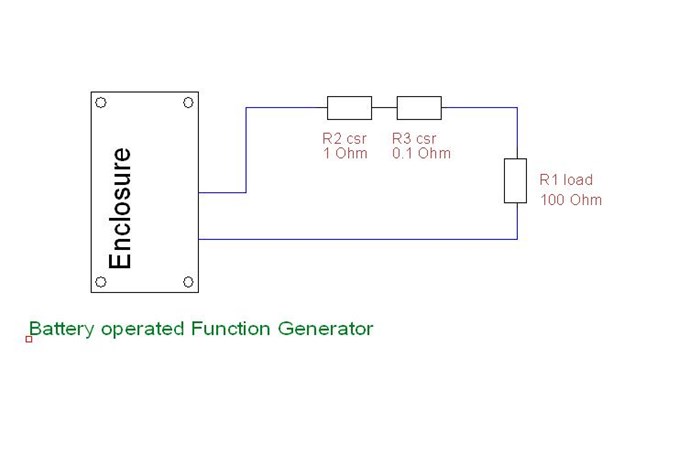
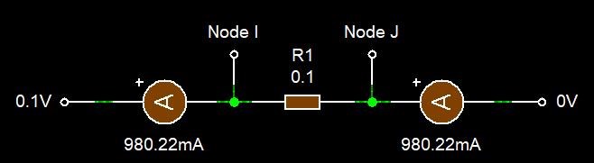
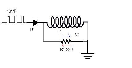
In the following circuits, you can see the Voltage Drop across the Load and the Current Sensing Resistor:
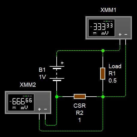
You can see, with a 1 Volt Supply, with a 0.5 Ohm Load, we get a greater Voltage Drop across the 1 Ohm Resistor than the Load, this means, more Energy is being wasted in the 1 Ohm Resistor than is being consumed in the Load!
This Circuit, because we introduced the 1 Ohm Resistor is now Mal-Performing by a factor of: 2
This circuit is NOT being measured properly, because we have changed the Circuit by introducing 2x In-Circuit Impedance is not greater than the Load!
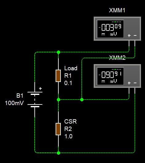
This Circuit, because we introduced the 0.1 Ohm Resistor is now Mal-Performing by a factor of: 0.2, an improvement of 10 times!
Now we can say we have reduced the In Circuit Impedance by 10 Times and also have a Circuit that is MUCH Closer to the actual way the Circuit is supposed to actually work!
It is Best Practice to measure a Circuit, with minimal Introduction of Impedances!
Current Sensing Resolution
How does Resolution work?
The Voltage Drop over a Resistor is using the Ohms Law equations to determined Current via: I = V / R
NOTE: Current Sensing Resistors are ideal at specific Ranges of Currents! Beyond those Ranges, they are not adequate and should be replaced with adequate Resistors!
As far as I understand, 50mV per division is Industry Standard Baseline for Noise test. So anything below 50mV per division is not useful for accurate Measurement.
People must think about this! This is important!
If we plot, the Voltage Steps vs the Current we see something that is very important:

The deviation between the 1 Ohm Resistor and the 0.1 Ohm Resistor grows linearly, this means, the Error is greater per Voltage Step, on the 1.0 Ohm Resistor! Yes, Error!
For every 50mV step, which is mA if on has the Scope set correctly, is: 10x
What does this mean? Well, we are able to Measure much more finely, we can Measure, 10mA to 1mA, let me show you:
There you have it, the Resolution is much greater on the 0.1 Ohm Resistor than the 1 Ohm Resistor, we lost a whopping: 45mA compared to the 0.1 Ohm Resistor: 4.5mA. So you see here, we have 10 times the Resolution with a 0.1 Ohm Resistor! 10 Times More Accurate! Simply: 0.1 Ohms is 10x the Resolution of a 1.0 Ohms Resistor!
A Resistor is a Resistor is a Resistor
NO! You need to carefully select a Resistor to do the Job! The exact same waveform should always be available every single time between the Resistors, except for the above stated Resolution issues! If the waveform is in any way distorted, throw away the Current Sensing Resistor and get a Good One!
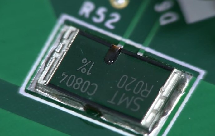
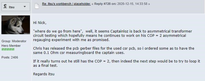
We have very carefully selected the 0.1 Ohm 1% Tolerance, Metal Strip Through Hole Resistor to accurately give measurements in median Current Ranges! Others can try to find fault all they like, but really, they just show how un-educated they are about such things!
A good Current Sensing Resistor should be nothing more than a piece of Wire of Known Impedance. Remember, keep all wire lengths short as possible! Always!
Conclusion
I hope you can see, why we are Light Years ahead of the other Forums! This, what I have shown here is simple stuff and they should know this stuff!
It is Industry Standard to use Very Low Resistance Current Sensing Resistors! This is very well known! Extremely Low Resistances, even as low as 0.0001 Ohms, or 100 μOhms.

I recommend all to do their own research and even check and double check what I say!
Rigol DP832 Precision Power Supply Current Shunt Resistor: 0.02 Ohms 1% Tollerance
The top of the line Keysight Current Probe uses a 0.1 Ohm Sensing Resistor! Thanks Jagau for the link!
Don't let yourself be led up the Garden Path, is easy, if you let this happen!
NOTE: This group of people that have been calling: "Measurement Error", on your machines for decades! Do you see why I have done what I have done?
Stick to Facts, Logic and what Makes Sense!
Best Wishes,
Chris


---open-tesla-research.jpg?width=20&crop=0,0,20,20)


