Clemente Figuera

  • Topic Is Locked
  • 49K Views
  • Last Post 16 July 2019
Wistiti posted this 09 January 2018


Hi guys!

In the past I play a bit with the Figuera concept. It use the POC as we already know the potential. I think this guy, Marathonman, understand the principe behind the Figuera device...

Chris, if there already a tread about Clemente Figuera, feel free to move this at the good place!


Order By: Standard | Newest | Votes
creasysee posted this 13 February 2019

Hi Marathonman and all!

I'm presenting a solid state version of part G (SSPG)! This is amazing! It works!!!

How it was made:

https://photos.app.goo.gl/mw8DsWQT7kF1UKxP9

Special thanks to Marathonman.

Regards, creasysee. улыбка

Aetherholic posted this 27 June 2019

Cornboy

Part G wire 93 turns 2mm x 1mm rectangular enameled copper 2.5mm spacing.

Build sequence:

1. Support the core on 2 empty wire spools

2. Epoxy 2 3D printed wire guides one each side and wait 24 hours for cure.

3. Start to wind the core.

4 Finish the wind.

5. Coat the windings liberally with epoxy. use 2 1mm PTFE sheets and two aluminium plates and clamp as hard as possible.

Leave 2 days to cure.

6. Remove the clamps etc. and clean up.

7. CNC the surface 0.05mm at a time until all wires exposed.

8. Mount on the frame.

9.  Mount the Part G head and finish up the wiring.


Aetherholic - One truth, One field

Marathonman posted this 13 November 2018

You have to admit the sheer genius of Figuera that designed this device 110 years ago thus realizing the total lack of advancements or suppression of our Scientific and Physics community since then. if you ask me total greed has overtaken Corporate world to the point of a total control scenario.

using induced emf within the circuit (Self Inductance) to control current flow at a rate of efficiency in the upper high 90's is and will always be sheer genius. using an active inductor to control current flow, splitting the feed into two independent feeds using magnetic fields in total unison, forward biasing like a mag amp, storing and releasing potential at a specific time needed to offset the rising potential drop. then adding a portion of the output to replace the losses occurred and give rise to amplification to the rising primaries,   good god what a sheer genius Figuera was.

PS. i get an apartment of my own next week thus my lab/work bench will live again........ let the rebuilding of the Figuera device commence.

back in the saddle again.

Regards,

Marathonman 

Marathonman posted this 10 March 2019

While i have some free time i am working on the cheapest timing and switching that can switch the Figuera part G in a make before break scenario with the ends switched on twice as long. i will order from Mouser and test the circuit before i post it on line.

I found some IGBT's  that are being discontinued so the price is really fantastic and a driver for .86 cents. i will either use an up/down decade counter or just a regular decade counter. the up/down will require and Arduino or something similar but the regular decade counter just  a signal generation of some type.

there can also be other ways to switch as with a PNP with the use of a 300 volt opto-isolator to isolate the two sections of high and low signal.

i will also be investigating the infusion of the secondary feed back with electronics also that can be switched from the same signal of the positive brush electronics but will start at the opposite side of part G's positive side and end on the opposite side.

IE... positive electronic switching starts from left to right and the secondary feed back from right to left to mimic the brush rotation.

Regards,

Marathonman

mabberflouth posted this 17 March 2019

Hi,

    i have bean lookin at this figuera generater for a while and this is the best place i have seen talking serius about it. im gonna build one of these and i hope i can help on the way.

i am new here and want to say hi to everyone on this generater. i hope i can get grate results.

ave a good day


mabberflouth


JohnStone posted this 23 May 2019

Hi all,

Finally I arrived here where Figuera cause is still alive :-) Some of you contributors might know me from other threads. I was silent now for several years but now - after my retirement - I search for new shores and want to deal with Figuera implementation.

I am a trained electronics engineer. But I know very well, that my training coverd a small part of the reality only. So please understand that I will be mostly silent for now while reading the wealth of contributions and learning basics of figuera configuration in my lab.

Thank you all for your contributions that gave me a steep learning curve up to now. 

Rgds

John

Marathonman posted this 24 October 2018

I have a chance to get a 50 to 60 thousand a year job over the next week plus my own place. If anyone has prayed for anyone before please do so for me now at this time. My sanity and this device hangs in the balance.

Regards,

Marathonman

Marathonman posted this 25 October 2018

Thank you very much, that really means a lot to me.

i have pounded the pavement every day for the last month contacting every agency i can think of.  i have 4 professional people helping me on my resume' before they see it Friday. plus i just attained a 500.00 home painting job for the owner of Door Vets.

i am sorry it is off topic but if it happens it will be balls to the wall for the Figuera device and all the readers and builders.

one way or another WE WILL SUCCEED ! My mission will help the worlds mission. the more that knows about the Figuera device the better human's life will be. 

regards,

Marathonman

romanta posted this 28 December 2018

Good day to all. In the old year I began a series of experiments on the topic of Figuera, at the moment what MM says is true. after I made the secondary coil half shorter, I got a much larger power output. I plan to cut the coil still, and see what happens, with the same input parameters of the primary coils.This is up to change.This is after the change.

romanta posted this 11 January 2019

in my free time I am engaged in preparing for the manufacture of a small device.

Marathonman posted this 22 January 2019

Good news everyone I just got hired and start Friday, give me a few weeks and let the building begin.

Regards,

Marathonman

Marathonman posted this 27 February 2019

The original replicator did mention that each half was to be calculated separately so your hypothesis has substantial merit.  when i build my next triplet i will investigate this.

Temple Transformer will not assemble my cores so i will have the arduous duty of assembling them myself which i have never done. well i will jump in with both feet because that is what we do.

I will have my cores in about two weeks primaries, secondaries and my C core part G.

Regards,

Marathonman

Marathonman posted this 18 March 2019

Weird, i just took the battery out and let set for a while then took another pic and it worked but i still lost over 30 minutes of video in the process.

Below is brush holder on top of my new C core.

wire is coming which is square for less precision grinding.

Regards,

Marathonman

alohalaoha posted this 09 April 2019

I will no longer post trying to convince or instruct people on the Figuera device. there is to many people that seam to be convinced their way is the highway even after my bench proven facts that are provable and replicatable. i will only post my build status and nothing more. ask a certain question in a pm and i will answer otherwise i will not respond to a question in the forum. i am through with uneducated or rather non thread readers that think the Figuera device is what ever their mind wishes to be at that moment in time.

good luck is all i may render, you will need it and then some.

Regards,

Marathonman,


Common Marathonman, take it easy man. You have our support and attention. Don't drop now till the finish line. Many people wait further instructions from you. Don't give up. This is my personal message to you. But do as you will. This is a MATRIX world and everything is possible, because it's virtual. Virtual like XP or WIN7 on your computer.

-------------

To all

This is very helpfull tool for Figuera buiders and many other researchers - Tiny Magnetic Poles indicator. Very usefull when expeimenting with coils.

From here:

https://acdc.foxylab.com/node/14

Hall sensor is from cheap computer cooler fan FS276 or VHE101B.

Pinout FS276 is same like VHE101B.

Pin1 = Vcc.

Pin2 = Collector of North Pole transistor - on sch. blue led.

Pin3 = Collector of South Pole transistor - on sch. red led.

Pin4 = Gnd.

That's all. Happy build.

Regards to all

Aloha

Marathonman posted this 15 April 2019

I am using Decade counters for my electronic switching part G. would like to use up and down decade but don't have time to study the circuit needed.

an curious if that is your primary shown.? forewarned that using solid cores for the secondary induces eddy currents and Hysteresis but would be fine for the primaries. Figuera used solid cores for his build but back then pure iron was much more available then now a days and much cheaper.  my complete set of 16 primaries and 8 secondaries ran me around 750 which to me is ok since it is top notch material being grain oriented also.

I am sorry for the ruff comments. after many, many years of explaining this device it seams very few actually try to confirm what i have presented on the bench.  benching is the only way to verify which is what i have done. it only take a few small tests on a small scale to verify all information presented.

hopefully i will resolve my jig issues during the week so i can assemble my cores this weekend. i am rigging up a tension system for my part G wire and will have it wound by this weekend.

Regards,

Marathonman

JohnStone posted this 23 May 2019

Hi Cornboy :-) Thank you for your warm welcome. Great you are active here! Looking forward for collective success.

Cornboy posted this 04 June 2019

 Hello All, finally got some time to play with my commutator, it is set up with Positive and negative feed back comm switch, and the feedback timing will be adjustable a full 180 degrees, just need to fit housing into a stand of some sort.

 Will be building 6 x coil triplets from modified audio crossover inductors with laminated cores for the inducers, and modified, shortened bobbins with as many offcuts from lams from the crossovers, that can fit, and then filling the air pockets with iron dust and epoxy.

 Regards  Cornboy.   smile


Cornboy posted this 28 June 2019

 Hi All, some shots of my mini coil setup.

 Regards  Cornboy.   smile

Peter posted this 22 May 2018

Hi Marathonman and Aetherholic,


First of all, thank you both for your (brilliant) hard work, and the fact that you're willing to share all the info needed to build this wonderfull generator. remember, you are not alone in this quest.. I think that besides us, a lot of people are trying to build this device..

Please don't let them trolls get to you..keep sharing info, and i am sure together we can build this thing, no problem.

Right now i am also building my part G..  al be it on a somewhat smaller scale.. ( look at the size of your C-core Marathonman, that's impressive..and plenty overhead..) .

Can't wait to see how both your builds are coming along..

I'll try and post some pictures of my build a.s.a.p. in the mean time,best of luck to you both. Namaste

Greetings from the Netherlands.

Peter

Marathonman posted this 22 May 2018

Welcome Peter is is always a pleasure to have one aboard that is eager to join in. i have ample information i have posted from my research and bench work that i hope you took the liberty to access. i do like the idea of a wire alignment guide on the bottom of part G. uniformity of  magnetic fields is definitely a must in this device so it is not a bad idea. the positive brush is on slip rings and the secondary feedback is commutated allowing both brushes to remain their sign always. yes, the secondary is mandatory for continuous operation replacing losses and amplification to the rising side of the device.

one thing i have to say to ALL is i am sorry for my harsh posts in which i have deleted. i have some pressing issues from here and other sites plus personal issues at home that caused my judgement to slip thus my patience also and for that i am truly sorry.  i have tried to maintain a pleasant posting atmosphere all while dumping a boat load of information from my research and bench work so others can test and replicate but recent pressing issues seemed to be a little overloading at times. the recent Law suit i filed on my mechanic was the final overloading issue along with cash flow problems.

Aetherholic;

 Thanks for the vote of confidence and the assessment of both brushes was very well said.

there are a lot of people out there that seems to think part G can be eliminated which basically boils down to a misunderstanding of just what part G does and how important it actually is.

part G spits the feed into two, forward biases like a mag amp, reduce and raises the currant on a continuous basis through self induction (C-EMF),  keeping them separate with north opposing fields,  stores and releases potential to either off set the rising side or stores the potential for the next half cycle along with the storing and released potential of the primary electromagnets then uses the secondary output to replace losses and amplification . all this happens inside of part G which will become the power supply once the starting is removed.

so all i can say is try that without part G and tell me how that goes.

PS. Eindhoven is a beautiful city especially at night.

WOW ! 10,000 views hit today.

Thank you all and THANK YOU CHRIS

Marathonman

Aetherholic posted this 01 June 2018

Marathonman

I have been busy with Part G 2.0

I finally got it working after re doing the main shaft twice due to CNC errors.

Here are some build pics:

Main 2 part shaft and bearings.

Base Plate.

Torroid supprt plate with 3 point adjusters.

Finished assembly

At speed.

The brush holders are no spring, centrifugal pressure, linear array needle roller bearings on the outside face to provide a zero friction surface for the brush.


Aetherholic - One truth, One field

Peter posted this 16 October 2018

Cornboy..


That's some build you've got there..  very nice indeed.


Aetherholic.


I chopped up the 130cm bar in pieces of 9 cm, then fired up the old Oxy- Acetylene torch, and heated them all up until they where REDHOT      after that, i let them slowly cool down to roomtemperature.  took about 10 minutes per core to get them that hot. 

This will remove any stress within the iron core, and make it less hard..(better magnet i think)

I will leave one core un-annealed, so i can compare the magnetic field strenght's, with the same coil setup later.

Next i will be sanding and coating them to prevent oxidation.


Kind Regards, keep on building...

Namaste

Peter Holweg


Aetherholic posted this 16 October 2018

Peter

Great, the annealed / un-annealed comparison will be of interest to all I think and quite valuable information.

Aetherholic - One truth, One field

Marathonman posted this 16 October 2018

Cornboy;

" but i couldn't get out of my mind Clemente's words" Resistance Pieces ", and the description of his Commutator as if it were separate from Part R the resistance."

That would be a big NO. Figuera was talking about the individual loops on the part G core that is a CLOSED CORE. any open core will NOT provide the necessary magnetic feed back to the system and losses will be through the roof thus self sustaining will not happen.

I know you have been through a lot building your system but quite frankly it has to be closed core or nothing remotely to self sustainment will take place.

a closed core is a must in this system but it doesn't matter what type of closed core you have as long as it is closed core. Aetherholic's core is functioning great as is my prelims on my C core so i already know it will work great.

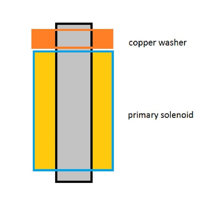
why in the world would you need resistance when SELF INDUCTANCE (Magnetic flux) controls the current flow and resistance is unrecoverable losses that should be avoided. this is why part G has thicker wire as to avoid undue losses from resistance thus raising the efficiency into the upper high 90's.

"My Part G is another story, huge power generation from the CIC core so I think you will see some surprising results with your C core when you build it"

I totally agree as all prelims in small scale proved this to be so.

" Wow silence is golden!!

 If you posted this on EF you would have an endless barrage of silly questions, and multiple Demands that you show proof."

BS, you would of been eaten alive from the wolf trolls and belittled like no tomorrow. why do you think i came here, to share with everyone in a relaxed environment.

welcome to the haven and thank you Chris for a job well done.

Together we can change the world.

regards,

Marathonman

Vidura posted this 25 October 2018

MM. I will also pray for you and whish youbthe very best. Sometimes we go thru struggles and difficulty, but then the good times comes. Also I want you to know that I have learnd many things from you, and appreciate your sharing. Regards Vidura.

Marathonman posted this 29 October 2018

Good news is the guy that did the tooling on the brush holder called and said come pick it up...... as in freebe.

that means i will restart with my part G C core and my custom brush holder so all is not lost.

Regards,

Marathonman

romanta posted this 29 December 2018

I also want to conduct an experiment using a copper washer at the end of the solenoid. As is known from old sources, a short-circuited turn of the wire at the end of the solenoid does not allow the magnetic field of the FAST core to leave the core. What will come of this, I will know only after the experiments in the new year of January 9th. because my lab will be unavailable.

Do not understand this as a deviation from the original Figuera device, I just want to make the device more economical in its work.

romanta posted this 16 January 2019

I greet you on this thread of the forum.
I made 6 primary coils and 2 of which I connected a push pool to the generator.
"important note" !!!! never use a switch on transistors to power such coils on a full iron core, this will lead you to the likelihood of fire due to overheating of the core !!!
The winding of the primary coils was 4 layers of 37 turns of wire of 1 mm diameter.
The magnetic field created by this coil with a core, in my opinion, is not strong enough for good operation of the device. I will add 2 more layers of winding. The current supply device of one triad 14 volts and 3 amps. I proceed to the manufacture of secondary coils and reactor G.


Marathonman posted this 18 January 2019

Exactly Zanzal,, the primaries are only reduced to get the seeping action across the entire secondary then back to full potential. This creates two electric fields superimposed over the top of each other along with the other reasons i had mentioned for the reduction of the primaries. If the primaries are taken down to far induction will fail as the coherency between the primaries is lost.

Regards,

Marathonman

Marathonman posted this 22 January 2019

On a very good note i have figured out how to switch part G with electronics exactly mimicking the brush rotation to a T but the amazing part is that will include the negative brush from the secondary feed back. Each start of the sigal run will be at opposite ends of the inductor but will be switched by the same signal generator at 60 or 50 cycles a second.

I will be discussing this with other members first before i present this proposal. This will make the Figuera device totally non moving but with the added expenses of electronics.

Regards,

Marathonman

Marathonman posted this 23 January 2019

Alset;


  The secondary loop back is and was the last piece of the puzzle to be solved. in the patent Figuera states a brush or group of brushes and sense part G becomes the power supply when the starting is removed then the secondary must be injected into part G.

with a second brush the secondary feed back can be ran through a commutator thus the positive side can be connected to the positive brush and the negative side can be attached to the second brush adding additional flux to the reducing primaries and the reducing side of part G thus giving the rising primaries an added boost at it's peak to replace the 30 % reducing primaries to get the sweeping action across the secondary.

the reducing side of the device will release it's reduced magnetic field into the system to off set the potential drop of the rising side of the system and the secondary is there to replace looses occurred and to give rise to amplification to the rising primaries.

if you are in the replication process please build your primaries no less then a 2 to 1 ratio at minimum that was the magnetic fields of the primaries can hit the needed pressure for the output.

The electronic switching i came up with will in fact mimic both brushes switching in opposite direction from the same signal generator on top of the inductor. the Figuera device CAN NOT OPERATE without the inductor so without it no self operation will exist.

Thank you very much. i have taken one hell of a beating in the last year but Marathonman is one hell of a trouper and will bounce back stronger then EVER !

Regards,

Marathonman

Marathonman posted this 14 February 2019

creasysee:

  How dare you even doubt me. ha, ha, ha, ha !

Congrats on the electronic part G and a wonderful build and attention to detail. you are most welcome my friend,  so many people doubted me for so long because they were totally stuck on stupid but along comes someone like your self that is open to new horizons just split the Figuera log in two thus making all the crap i took for sooooo long totally all worth it.

I do have to ask are you using PNP's or NPN's with drivers.?   my electronic design was with small NPN's switching big PNP's that can be driven by all sorts of things. but we all know i am with mechanical at this time.

isn't it amazing that inductance can control current flow. just switching the winding count within the time constant of the circuit causing a current reduction. this is the very reason i share with people, to share what i have learned in hope we can change this F up cesspoll we call living being constantly controlled by some greedy ass wipe. 

just a word to the wise, the end channels on both ends must be on longer than the one's in between them to get the inductive decay roll off to mimic the AC wave exactly.

PS. "R" does not exist, it is part G's magnetic resistance (Inductance) drawn in it's elementary form to facilitate the comprehension of the device. R is part G and part G is R,  they are one and the same, Inductance.

CONGRATULATIONS ON A JOB WELL DONE IN LEARNING AND BUILDING.!

Regards,

Marathonman

Chris posted this 23 February 2019

Yep, Trolls are Not Very Smart:


Almost 13 weeks and nearly 20,000 views, the globe is pretty red now! The Trolls still visit us, they just know they have Zero chance of staying alive here! It appears the entire Internet has waited for a safe secure place to plan their work flow!

The other forums are dead, all chatter is the same chatter they were messing around with 10 years ago! Old news for all here!

Go MM, keep up the good momentum! Many visit to see your progress! All others here also!

   Chris

Ourbobby posted this 20 March 2019

Hello, 

 This is my first post here. I have been following Figueras around the forums for a couple of years. Follow the information! I am collecting components for a digital build. I have just  collected a toroid - or a piece of steel bar with a hole in it! The dimensions are diameter 180mm, inner diameter 88mm, height 58mm. Next move on this is to decarbonise it in my small kiln. Then wind a Part G+R. I am a little worried that I might have too much iron here. Well I'll suck it and see.

Regards

Ourbobby

alfizik posted this 20 March 2019

Hi guys!
I read this forum with great interest! Many thanks to Chris for ordering this resource!
I am very interested in the prospect of recreating the Figuero device.
Thank you Marathonman for the leading role and a lot of useful information and tips!
I will try to post a photo of what I have worked out lately.

Marathonman posted this 04 April 2019

Many, Many thanks !. i am so tired i can't think straight. finally received my IGBT's..... ALL of them. at $1.95 average price for 405 WATT monsters i couldn't go wrong. my electronic test board will be in next week and also my reorder of epoxy came in safe and sound this time. pic bellow of the beasties !

will start assembling cores this week end and bobbins if i can hold my eyes open long enough.

Regards,

Marathonman

Marathonman posted this 15 April 2019

Didn't get a lot done today. assembled table top drill press and drilled aluminum plates for mounting of part G's core and of the motor mount to plates. can't believe i found the motor screws at the hardware store. glued half round on part G's core face and sanded, cut aluminum 3/8 " threaded rod to 1 foot lengths with washers and lock nuts.

My jigs were a total flop because of the weld that worked it's way into the inside of the jig. spent all day with Dremel tool trying to rid the weld to no avail. ruined every bit trying to grind it. Dremel sucks and is putting out crap on the market. i need to figure out how to remove the weld on the inside of the jig before i can assemble the lamination's.

Picked up more ecofy cloth for the bobbins as well as a ton of tools, clamps and such. the sanding disc i purchased is 8,000 rpm rated so that is good at 3100 rpm of the drill press.

Below is an 80 dollar table top drill press that worked well beyond my expectation and then some and some build progress.

Regards,

Marathonman

Chris posted this 06 May 2019

@All Readers, I agree with Marathonman!

Well summed up and nicely put Marathonman!

Much information is shared here and resources on my website. hyiq.org.

   Chris

Aetherholic posted this 06 May 2019

Also everyone should read the results of the experiments that have already been done and published on this thread. All the answers are there to be interpreted and used in further development, both success and failure. I have so far built 2 different working part G's and built a full array of coils and published some results. When Marathonman finishes his part G there will be 3 different versions of Part G working. Build upon what has already been done.

Aetherholic - One truth, One field

JohnStone posted this 11 June 2019

Want to share some knowledge regarding chokes.

Normally the core at chokes has a tiny air gap in order to get a linear behaviour. This is essential for audio circuits. On other hand for power supplies a linear behaviour is not important. So we can use an old trick.

Grab a transormer and short circuit the high voltage winding. Use the low voltage winding as choke. You will be amazed how sturdy this pet can be. Most sturdy will be a MOT. Amazingly this short circuit does not behave like so. It just allows the magnetic flux to continue as long it feels to be necessary.

In old times when they still had that POTS (plain old telephone) system they had special relays with considerable delayed reaction. The only trick used was to cover the winding with a sleeve of copper. 

Please study the notions of Chris regarding short circuited windings in his setups. Look up Utkin's paper for same reason.

In part G we might have similar ingredients. The contact - make before brake - enables constantly one shorted winding traveling round the core. One effect is that the current will never be interupted totally and the flux can make use of one shorted winding in order to continue - hence less overvoltage at the contacts.
I am not sure if this ingredient has further effects but it might have. Food for thoughts for all of us.

Vasile posted this 01 July 2019

I can relate to what you are saying, sure there are a lot twisted things in this world as you have enumerated some of them. I too have tryed to change things around me, mainly people. But it didn't went that well and the reason I haven't succeded is because of me. I didn't do it right. That I can tell you with 100% certainty.

You see, aside the bad things in life there are also the good ones, like the laws that govern nature in general. Think about the beauty of a plant, the consistency of the suns movement or simply the fact of being alive, being conscious. So if things are the way they are, is most probably due to a main cause. Most of the people in this world are like ships without guidence and they go where the general stream of water takes them. If you don't like where the general stream of water goes, then do something about it. If you look back in history, it was always the power of small groups of people and there ideas that produced the most radical changes in the world.

All the best,

Vasile


Zanzal posted this 11 January 2018

i am a man of my word and live by my word and you people will get the information in my head if it kills me or they kill me first.

No worries man. As of this year (((they))) don't have the influence they once had. Also I don't think they kill people for knowing about FE or how to build FE devices. Though I am fairly certain they killed people who tried to upset the balance or status quo or who had invented something truly special. Unless you are manufacturing anti-matter in your basement or trying to put a FE device in every home/car you don't have anything to be concerned about IMO.

Chris posted this 11 January 2018

As of this year (((they))) don't have the influence they once had

World Wide Eutrophic Smack Down of Evil - I am totally tickled about this! (((they))) have been reaped and this time the Grim Reaper is shinning light for all!

Team Q

   Chris

Zanzal posted this 11 January 2018

Good info here, definitely convinced me to give this one a try. For a small prototype what is the recommended construction recipe here. I understand the coils all need to have a soft iron core (which is difficult and somewhat expensive to source). Can anyone recommend based on experience:

1. minimum number coil sets (7 shown in the patent, can it be done with 1 set, 2 sets, etc?)

2. minimum/maximum dimensions for soft iron cores for N/S coils and also for pickup? 

3. wiring gauges for wiring for both the N/S coils and also pickup?

Just looking for basic replication starting point, not for use necessarily on a practical scale. 


Wistiti posted this 13 January 2018

Hey MM, it is a pleasure to have you here with us!


I want to start with a welcome to finally a forum where people can freely share their building experiment without the fear of being challenged by bad mind people...

Here people are free to experiment with the bucking coil ,POC, technique (cause we already know it work) or any other approach they want. 

The main idea here is to build, learn and share together.


With that say, please do not be upset if the “mass” do not replicate what you are sharing.... This “mass” builders is not so high in number and some share their experiment and some other prefer to not... That the way it goes and it is ok like that.

Anyway, everyone learn and progress at their convinience...

Again I’m happy to have you here sharing!

Zanzal posted this 17 January 2018

WOW ! i just laid out so much info to the figuera device and all you can say is is a comment about something i completely forgot that was on that graph about a book that is basically a complete lie in the first place twisted by man to suit his own needs as a tool of control.

it seems i might be in the wrong place to present the Figuera device and need to reassess my reasons for being here .

Marathonman

Greetings Marathonman,

Yes, I appreciate your sharing and being here. I have a religious obligation to combat heresy just as I have an obligation not to lie or to steal or to harm other people. We have to be true to our beliefs. Feel free to express yourself in any way you see fit, I shall do the same and with much politeness if at all possible.

norman6538 posted this 07 February 2018

I did Marathonman's Test 1 and got very little current and the same for test 2. I suspect some coil/magnet geometry problems and will increase the repelling magnets gap to 1/2 in from 1/8 so it will be about the same as the coil width so the same pole is approaching the coil and also leaving the coil out the other side.  I will be pushing the magnets through the coil hole so its more like the Figuera configuration instead of pushing the past the cored coil. I use black silicone seal to hold the magnets and that takes a good 12 hrs to hold. Hot glue will not hold the repelling magnets. I am using 3/4 ceramic magnets.


Anybody else get some better results?


I tested the wider gap between repelling magnets and did not get a greater current.

Now what?


Norman

norman6538 posted this 07 February 2018

Could you describe the physical movement that you used for the test. Most people pass a magnet over one of the core ends...And when you do that you will get one voltage polarity as they approach each other and another when they leave each other. But I chose to pass my magnet through the coil and you get the same voltage polarity approaching and leaving as in passing the core.

Mechanically going through the coil does not make a generator. Were it not for my such experiments I would not understand this at all.

Now picture a magnet being flipped so that N goes in and gets flipped so that N also comes out which means the coil voltage polarity does not get flipped....Figuera did that so that he got the same polarity  approaching and leaving instead of switched polarity. But I am not sure about the current doubling. My test will show that when the glue dries over night.

Norman


Norman

Aetherholic posted this 12 May 2018

Some more progress information.

Here is a not too good quality scope pic of the part G outputs N and S at low speed (yellow and blue).

So here is confirmation of the dual sine waves.

I can also confirm that there is huge energy stored in part G as if the brushes lift there is a very big negative spike despite running with magnet wound coils so the inductive collapse is mostly the energy in the torroid.

Aetherholic - One truth, One field

Marathonman posted this 03 September 2018

Here is a drawing of what my part G is going to look like when i am finished with it. i was going to have aluminum rod like in the pic 4 days ago like the part i found online but it is cheaper to go the threaded rod rout. the center section is for the bearing support to take all the pressure off of the motor shaft coupling. maybe at a later date i will change to the aluminum rod for looks.

Regards,

Marathonman

Topic Is Locked

We're Light Years Ahead!
Members Online:

No one online at the moment


What is a Scalar:

In physics, scalars are physical quantities that are unaffected by changes to a vector space basis. Scalars are often accompanied by units of measurement, as in "10 cm". Examples of scalar quantities are mass, distance, charge, volume, time, speed, and the magnitude of physical vectors in general.

You need to forget the Non-Sense that some spout with out knowing the actual Definition of the word Scalar! Some people talk absolute Bull Sh*t!

The pressure P in the formula P = pgh, pgh is a scalar that tells you the amount of this squashing force per unit area in a fluid.

A Scalar, having both direction and magnitude, can be anything! The Magnetic Field, a Charge moving, yet some Numb Nuts think it means Magic Science!

Message from God:

Hello my children. This is Yahweh, the one true Lord. You have found creation's secret. Now share it peacefully with the world.

Ref: Message from God written inside the Human Genome

God be in my head, and in my thinking.

God be in my eyes, and in my looking.

God be in my mouth, and in my speaking.

Oh, God be in my heart, and in my understanding.

Your Support:

More than anything else, your contributions to this forum are most important! We are trying to actively get all visitors involved, but we do only have a few main contributors, which are very much appreciated! If you would like to see more pages with more detailed experiments and answers, perhaps a contribution of another type maybe possible:

PayPal De-Platformed me!

They REFUSE to tell me why!

We now use Wise!

Donate
Use E-Mail: Chris at aboveunity.com

The content I am sharing is not only unique, but is changing the world as we know it! Please Support Us!

Thank You So Much!

Weeks High Earners:
The great Nikola Tesla:

Ere many generations pass, our machinery will be driven by a power obtainable at any point of the universe. This idea is not novel. Men have been led to it long ago by instinct or reason. It has been expressed in many ways, and in many places, in the history of old and new. We find it in the delightful myth of Antheus, who drives power from the earth; we find it among the subtle speculations of one of your splendid mathematicians, and in many hints and statements of thinkers of the present time. Throughout space there is energy. Is this energy static or kinetic? If static, our hopes are in vain; if kinetic - and this we know it is for certain - then it is a mere question of time when men will succeed in attaching their machinery to the very wheelwork of nature.

Experiments With Alternate Currents Of High Potential And High Frequency (February 1892).

Close