Diakoptics, breaking a problem down

  • Topic Is Sticky
  • 1.7K Views
  • Last Post 08 June 2020
Chris posted this 16 February 2020

My Friends,

Many of you have heard me talk of Diakoptics.

Diakoptics Definition:

Noun
(uncountable)

The act of breaking a problem down into components which can be solved independently before being joined back together to obtain a solution to the whole problem.
Origin
From the Greek dia (system) + koptic (tear).


Many of you know Gabriel Kron, Tom Bearden talked about Kron being Floyd "Sparky" Sweet's Mentor. Well some history:

In systems analysis, Diakoptics (Greek dia–through + kopto–cut,tear) or the "Method of Tearing" involves breaking a (usually physical) problem down into subproblems which can be solved independently before being joined back together to obtain an exact solution to the whole problem. The term was introduced by Gabriel Kron in a series "Diakoptics — The Piecewise Solution of Large-Scale Systems" published in London, England by The Electrical Journal between June 7, 1957 and February 1959.


Using Diakoptics on Partnered Output Coils:

We are going to make use of Gabriel Kron's Diakoptics to make sense of Partnered Output Coils.


Step One

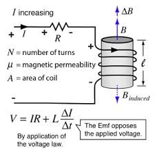
The Input Coil, work toward a simple Circuit, something like this:


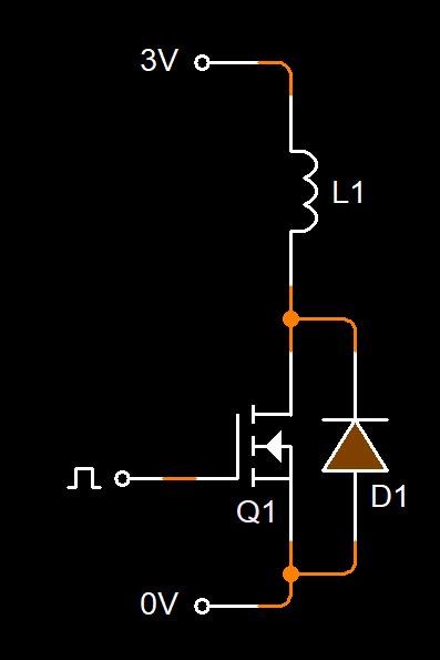
Get the Switching clean and sharp. Make this circuit reliable and trustworthy. Over rate your mosfet so you can turn your input up with no trouble. Make sure you have a super low RDSON.
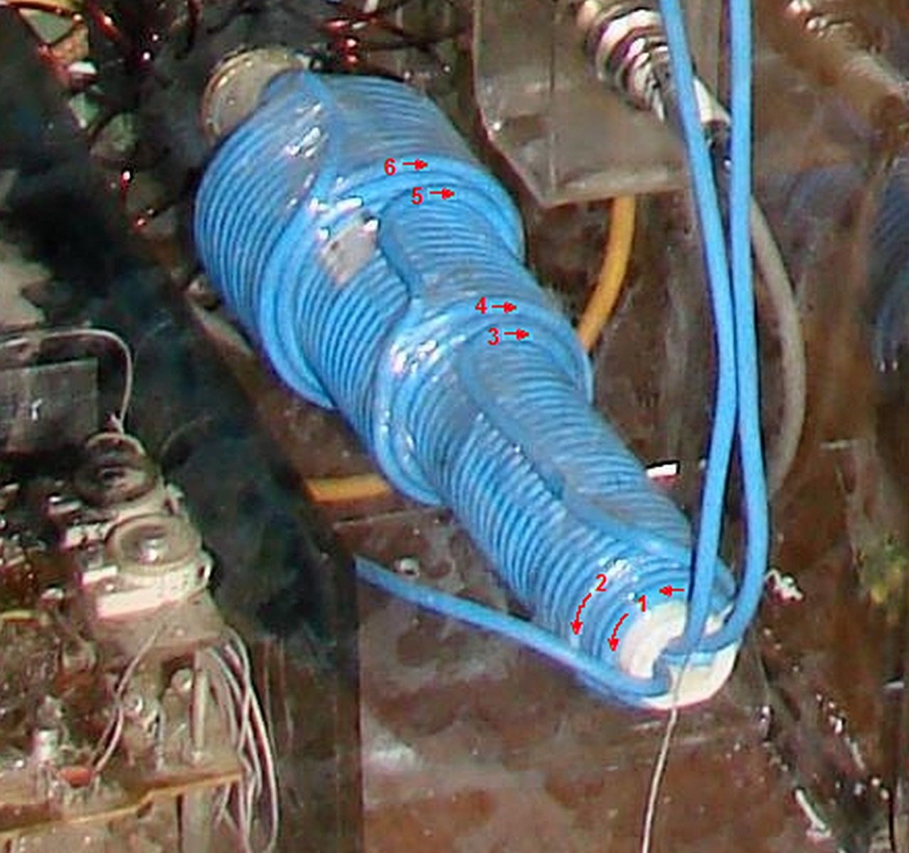
 

Step Two

Add one Partnered Output Coil. Make the machine work as a simple Transformer. Standard Electromagnetic Induction from Input to Output should ensure an approximate 80% Efficiency at least.


This is a step up Circuit. The Voltage on the Output should be X Number of Turns increased. Remember, Partnered Output Coils are always more turns than the Input.


Step Three

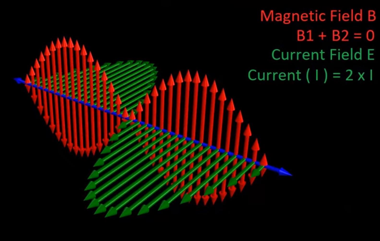
Partnered Output Coils must oppose each other! This means, one Partnered Output Coil must Assist the Input Coil! One Partnered Output Coil will oppose the input. You see here, adding our third Coil, we have exactly that:


So I urge all Experimentalist's, add the components one at a time. Make sure they all have the desires Polarity and function. This is really important.


Think of this as a Jigsaw Puzzle, in its smallest possible pieces. Add one piece at a time, make that piece do what its supposed to do.

NOTE: An 80% efficiency from Input to Output is standard Transformer Technology! Standard Symmetrical Electromagnetic Induction! Adding another 80% gives us 160% and this is one of the most common figures where most people reach. This sentence has meaning, please understand whats being said here. One Coil assists the Input and must therefore add's another 80% efficiency to the machine on top of the existing 80% efficiency!

Best wishes,

   Chris

Order By: Standard | Newest | Votes
Chris posted this 17 February 2020

Hi CD,

You are right! I may not have been clear on the Turns thing! I am sorry!

Its true that many Factors play a role here.

But in the Context, as a Transformer, if the Primary has 10 Turns and has 10 Volts applied, then each turn is 1 Volt. This means each turn will have an approximate 1 Turn 1 Volt ratio also. So for 20 turns on the Output Coil in the Transformer we would have approximately 20 Volts.

I found it interesting, Floyd Sweet used a 1.11 form factor equation. So our 1 Volt would be 1 x 1.11 x 20 turns = 22.2 Volts. This accounts for loss and in-efficencies in the Transformer.

Now as Step two is get the transformer working, I have used that Context. We both know a little more how this works. The Two magnetic Fields, from Each Partnered Output Coil have their own Time Rate of Change of their Magnetic Fields and this is at a resonant point, where the Rate at which this happens is determined by the Partnered Output Coil Characteristics themselves.

EDIT: 

Don Smiths turns was 16 each Partnered Output Coil. 4 Turns on the Primary. That's a 1 : 4 ratio. For every 1 volt for each turn on the primary, that's 16 Volts on the Secondary.

Floyd Sweet, for every one turn on the Primary ( 48 turns ) to the Secondary ( 240 Turns ) that's a 1 : 5 Ratio.

Akula commonly used a 1 : 3 Ratio but this did vary!

All these combinations is the part where we have to experiment to find the best parameters.

Best wishes,

   Chris

Chris posted this 18 February 2020

Hey CD,

Yes, Floyd Sweet drew a diagram: in the original folder: Sparky Visit


Unfortunately I was not able to verify this. But I am confident some of this is Floyd's hand writing.

No I have not incorporated the 1.11 in my work. Not yet. I aim for best Output.

Many times Floyd mentioned Faraday's Laws.

   Chris

Chris posted this 18 February 2020

Hey CD,

Very nice! Well done!

Much of whats on the above Floyd Sweet Documents is non-sense. But we can take what makes sense and can be verified and learn from that.

Nice work my Friend!

   Chris

Chris posted this 19 February 2020

@CD,

In Step 2, something you said, in the Video Title, that made me think that it may be worth looking into this a little more.


Voltage is the Time Rate of Change of Current.

While the Input Coil Current changes in Time, the Output Coil Voltage changes in Time! When the Input Coil Current is steady, the Output Voltage is Steady, no change in Voltage. The relationship is:

diInput ≅ dVOutput


Changing the Input Current Changes the Output Voltage.


Current flows due to Opposite Magnetomotive Force.

If the Input Coil has a steady Current, the Output Coil Current is Steady. Instantly switch off the Input Coil Current, the Output Coil Current instantly switched off. The relationship is:

diInput ≅ diOutput


Changing the input Current Changes the Output Current.

Where:

  • d = Delta, often seen as: δ or Δ the Change
  • i = the Current.
  • V = the Voltage.
  • = Approximately Equal to.
  • Input = the Coil, Primary.
  • Output = the Coil, Secondary.


Its all about the Change! What happens when something Changes!

I am specifying the Force to Force relationship. I am not saying the measured Value! The Values are not the same, E.M.F vs M.M.F... So, if you see, the relationships I am pointing out, this will help immensely in the understanding and the replication process of Step 2!

That's why, when you say: "Great duty allows great voltage" there appears to be more Voltage because more Input Current is Changing in Time, and then the Output Current is Supported for Longer the the Input Current. More Current In and therefore more Current Out! Does this make any sense?

Have I explained this with a decent description?

Best wishes my friend,

   Chris

  • Liked by
  • Augenblick
  • Kritischer
Chris posted this 19 February 2020

Hey CD,

Step 3 is how to redirect these effects, the effects in Step 2.

Redirect the Effects so each Partnered Output Coil have the same Interactions, the same effects. The Input Coil is the excitation coil for these effects.


Best wishes,

   Chris

Chris posted this 27 February 2020

Hey CD,

Good work! I left this message on your video:

+1 - Good work CD. Observing the Output, when a Frequency and Duty Cycle combination is found, your Output will peak, go to maximum. So viewing your output will also help. The Voltage gained on the Output is important, as the Coils slap together, this "Generates" a Voltage. Remember our Delayed Conduction Techniques. The greater the Voltage the greater the Current because I = V / R, Ohms Law. If the Partnered Output Coils have too much Impedance, AC Resistance, Resistance to Change of the Magnetic Field, this can also be a problem.


Of course, we all know, maximising the Output for the least Input is our overall goal. Observing the Output, finding what direction what changes made, will show a pattern. If you follow the pattern, what the Partnered Output Coils like to see, then its only a matter of time before you find the right configuration.

Best wishes,

   Chris


P.S: in Low Frequency situations, < 7Khz or so, the maximum Noise will be heard.

Chris posted this 08 June 2020

My Friends,

Most of you know, now, the work I share is based on Floyd Sweets work. Why are we so far ahead of the other forums? Because we have used Diakoptics! Broken the problems we have faced down to the smallest possible pieces and worked on the smallest possible problems!

Fighter has made some real success, and many that have replicated my Non-Inductive Coil Experiment, many of you have had a good successes! These success have mostly because we have learned the basics, we have a very good grasp of the fundamental requirements of Energy "Generation"! I have covered this perhaps in greater detail than any other website on the entire internet!

As our Friend YoElMiCrO has said:

The best way I've ever seen to get energy from the E-field is the previous post, testing Floyd Sweet's idea that only E remains while we cancel H.


Huge amounts of Energy can be extracted under Resonant Conditions! The Electric Field is in the Space outside the Coils, the Coils are filled with Electric Field, but only when the Magnetic Fields are Opposing.


My Friends, I have covered this stuff for so long, I am sorry you are no doubt board of me saying, but this is important, its the path forward.

If you want to build Above Unity Energy Machine, like most of our Members here at Aboveunity.com, then this is a process you need to follow. 

Remember Tariel Kapanadze Grenade Coil:


The same thing is occurring, the Clock Wise / Counter Clock Wise Turns, they Cancel the Magnetic Field, and the create a large Electric Field, at least 2x the initial amplitude, as we have been told, remember this is all a verification of Floyd Sweets work:

If the directions of the two signals are such that opposite H-fields cancel and E-fields add, an apparently steady E-field will be created. The energy density of the fields remain as calculated above, but the value of the E-field will double from E / 2 to E.

Ref: Floyd Sweet Nothing is Something.


Tariel Kapanadze's Coil is in Resonance, remember what Ruslan told us:

 All these systems operate on the basis of standing and traveling waves. It is necessary first to catch the motion of particles in the coil.

...

Only at HF frequencies no ammeter will help and you will need to catch an oscilloscope. The first rule: Wind the coil 40 meters. 2. Find out its resonant frequency (1/4 wave) Inductor 1/4 = 10 meters of the same wire (for example, 2.5mm) Connect the generator to a 10 meter coil, drive the rectangles at a frequency of 1 MHz and crawl higher until 40 meters do not appear sinusoid. The maximum amplitude. The generator is desirable to take a normal, laboratory! With output adjustment from 0 to 20 volts. We achieve maximum amplitude and move tenths of a kilohertz until it starts to dance. This is your wave resonance !!! 


For all, here, they know this stuff already! Others, come here to read, that want to learn and share, Be part of Something Better, then they can learn from us!

The Resonance, it is Magnetic Resonance. Others on the other forums, still actively misleading others, not telling the truth, if you choose to follow them, then you will not learn anything of value, you need to read and learn our stuff!

Now, remember, there are parameters to Coils:


All these parameters play a role! The Coil interactions together, play a role! Floyd Sweet spoke of many of these parameters in his Paper: Nothing is Something. Including things like Aspect Ratio and other things.

To solve problems, use Diakoptics, break the problem down to the smallest possible piece and solve that, then the next and the next until all the problems are solved!

Best wishes, stay safe and well in these dire times,

   Chris

We're Light Years Ahead!
Members Online:
What is a Scalar:

In physics, scalars are physical quantities that are unaffected by changes to a vector space basis. Scalars are often accompanied by units of measurement, as in "10 cm". Examples of scalar quantities are mass, distance, charge, volume, time, speed, and the magnitude of physical vectors in general.

You need to forget the Non-Sense that some spout with out knowing the actual Definition of the word Scalar! Some people talk absolute Bull Sh*t!

The pressure P in the formula P = pgh, pgh is a scalar that tells you the amount of this squashing force per unit area in a fluid.

A Scalar, having both direction and magnitude, can be anything! The Magnetic Field, a Charge moving, yet some Numb Nuts think it means Magic Science!

Message from God:

Hello my children. This is Yahweh, the one true Lord. You have found creation's secret. Now share it peacefully with the world.

Ref: Message from God written inside the Human Genome

God be in my head, and in my thinking.

God be in my eyes, and in my looking.

God be in my mouth, and in my speaking.

Oh, God be in my heart, and in my understanding.

Your Support:

More than anything else, your contributions to this forum are most important! We are trying to actively get all visitors involved, but we do only have a few main contributors, which are very much appreciated! If you would like to see more pages with more detailed experiments and answers, perhaps a contribution of another type maybe possible:

PayPal De-Platformed me!

They REFUSE to tell me why!

We now use Wise!

Donate
Use E-Mail: Chris at aboveunity.com

The content I am sharing is not only unique, but is changing the world as we know it! Please Support Us!

Thank You So Much!

Weeks High Earners:
The great Nikola Tesla:

Ere many generations pass, our machinery will be driven by a power obtainable at any point of the universe. This idea is not novel. Men have been led to it long ago by instinct or reason. It has been expressed in many ways, and in many places, in the history of old and new. We find it in the delightful myth of Antheus, who drives power from the earth; we find it among the subtle speculations of one of your splendid mathematicians, and in many hints and statements of thinkers of the present time. Throughout space there is energy. Is this energy static or kinetic? If static, our hopes are in vain; if kinetic - and this we know it is for certain - then it is a mere question of time when men will succeed in attaching their machinery to the very wheelwork of nature.

Experiments With Alternate Currents Of High Potential And High Frequency (February 1892).

Close