L0stf0x's Self oscilating POC transformer

  • 2.3K Views
  • Last Post 28 December 2020
L0stf0x posted this 08 May 2020

I am not sure That this is appropriate for this thread! I saw the remarkable video of Chris with the magnetic field diode! Remarkable test you made there Chris! I have no words!! Well done my friend!!

So I wanted to try an idea based on Chris test... but combining a reed switch and a magnet... 

Its a transformer with one primary and four secondaries ( 2 x POC style ).

Now the test as Chris did not succeed, because the core concentrate the field and passes from inside the diode coil, so air core needed for field diode to work correct.

But As I was playing I manage to get the leds on with <2μA. Before I make the video I had it at least one hour with current stable 0. Then I move the magnet a bit and it went to 1μA - 2μA. 

The leds are not fully bright but they are well on as you see at the video.

The voltage at battery is stuck to the same voltage (but the batteries are high capacity so this is normal).

What is not normal is that even I take the leds off the circuit or I have them on, the current is the same. They are not seen as a load somehow. And leds should consume some at least mAs .. But any way you tell me if its worth to examine it further ..

I have to go now but I will draw a schematic and get back later today..


Order By: Standard | Newest | Votes
L0stf0x posted this 28 December 2020

Oh I see! as protection for reed! But at your circuit the reed is not in danger.. It is driving the mosfet. At my setup there is no mosfet. All hard work is done by reed it self. Maybe a simple fuse will do the job at my setup.

But is a nice solution of mosfet version! Thank you YoElMiCrO !cool

This is the basic circuit I am working on.

YoElMiCrO posted this 28 December 2020

L0stf0x, you leave everything the same, you don't modify your circuit.
The diagram is just so that your reed-sw doesn't dead
by the current that passes through it.
The anti-parallel diode to the MOSFET, as it is faster
that the one with the parasite said mosfet, will drive
at the moment of negative current seen
from the positive source rail.
In two words, this circuit is just so it doesn't dead
your reed-sw and don't miss the charging effect.

YoElMiCrO.


L0stf0x posted this 28 December 2020

Excelent! thank you!

YoElMiCrO posted this 28 December 2020

Here the best image L0stf0x.

YoElMiCrO.

L0stf0x posted this 28 December 2020

Hey YoElMiCrO! thank you for sharing, I sure can implement it. Looks easy, but I am not sure I can read the values.. If you can post a larger image at the circuit side, or just write the values would be helpful. Coil inductance or resistance if known?

I really want to hear your theory!! And I guess everyone here

Yes the reel is 3D printed. 

Nice!!  Many interesting testing setups to do at holidays!

YoElMiCrO posted this 28 December 2020

Hello everyone.

L0stf0x if I may, you can implement this image.

I already have an answer to your question, but the explanation is
long and I don't have the time right now.
However, your last experiment is called the attension
because it's related to a theory I have about matter
and I intend to do it like this in the image above.
The reel is printed on a 3D printer just like yours I think.
When I do this experiment, I'll let you know my conclusions.

Thank you from now on.

YoElMiCrO.

Chris posted this 27 December 2020

Hey L0stf0x,

We all are, at least mostly, half wave rectifying, so no AC, only DC, but same ideas are involved.

Best Wishes,

   Chris 

  • Liked by
  • cd_sharp
  • L0stf0x
L0stf0x posted this 27 December 2020

The auto-amplifying power should have a limit up. Nature works with limits. Battery I guess puts the limits... But reed can not withstand to reach that limit.. So in realistic world, the type of wave should be something like this. 

L0stf0x posted this 27 December 2020

Hey Wistiti! VERY Good idea!  is something I haven't tried at secondary.

I have tried at primary the transistor setup but maybe you are more lucky my friend I will wait for your results!


Questions:

Do we get AC circulating through battery!?? does the AC is passing through battery??

A friend send me this document from the book of Don Smith ("Vacuum Tubes"). Saying about the negative resistance...

Ok but what really is trumpet wave? As you see at the drawing the wave does not decrease at all! it is only increasing!

I was searching and found this video from 2012 from RomeroUK. This is not the growing effect that I witness!! This is just a trumpet wave with endings. An amplified effect but not a growing effect!

He uses similar setup but he use spark gap. BUT the waveform that he shows is not relevant to the growing effect. 

The growing effect was periodically continuously growing as a whole. I was able to hear it wirelessly from the speakers of pc, like someone was turning the volume up and up... It is totally different.

This also is an amplified effect and not a growing effect!


Wistiti posted this 26 December 2020

Hi L0stf0x my freind. I'm currently working also on it... This is the way I will drive it. (See attached picture)

I will post my results on my thread.

Thank to be here!

Attached Files

Chris posted this 26 December 2020

My Friends,

Most of you will already know this, or at least understand this.

As a machine, that has Current Amplification properties, moves from out of resonance, into resonance at maximum Voltage, the Waveform shows this very characteristic. In other words, we get a Trumpet Waveform:


Current requires Voltage, and is dependent on Resistance, in other words Ohms Law: I = V / R. So any machine that can change any of these parameters, has the ability to increase its over all volume of Output. Voltage V, comes from dI/dt, the change in Current, in these machines. di/dt is the Change in Magnetic Field, B/dt, they are the very same things!

Great Work L0stf0x! Again, thanks for sharing!

Best Wishes,

   Chris

thaelin posted this 26 December 2020

  Reeds were never designed to carry current. If switching a coil on and off of sizeable inductance, there will be a large plasma flash on opening. That burns the contacts quickly. Use the reed to trigger a transistor or gate driver for a fet. Hall triggers work great too but have to be powered separate. Have a copy of Kones bi-directional fet circuit around here some place if interested.

thay


L0stf0x posted this 26 December 2020

Thank you Vidura! Your thinking is very logical and correct. But let me try first with spark gap and high voltage (not very high). Just for curiosity, I ll do some experiments and I ll update..


Vidura posted this 26 December 2020

Hey Lostfox, It seems there is a very significant current in the device, if the reed dies so fast. A solution could be a solid state switch triggered by a hall sensor circuit. Only if it has to handle bidirectional currents, a jFETwould be required, or two MOSFETs back to back. Only thinking.... Vidura

L0stf0x posted this 26 December 2020

Yesterday I repeat it with a similar size reed and I had it again for just ~2 seconds! Reed is dead again. My nerves going bad

I still cannot understand the cause of this. Also the problem is that I cannot read the oscilloscope and multimeters freeze before you even read a voltage.

I will try with transistor, but I know it will not work with transistor... I thinking of making a rotary distributor multi switch to get more control. I know this needs external power but we interested at the phenomenon here. First we need to understand it and also be able to measure the damn frequencies somehow. 

The only high frequency reeds are those

https://standexelectronics.com/products/high-frequency-reed-switch/

but I can't find them anywhere!


Edit:

Every reed has its own exact resonance frequency, even same type have big differences. Even if I get the best reed it will be destroyed in few secs. 

The only alternative to reed switching is the spark gap as I get it. So I decided to go high voltage and try similar setup again.

L0stf0x posted this 22 December 2020

Exactly Chris!!

I found a way to fit a capacitor and change frequency up.. I get better results now!

I need some time to test. brb


Chris posted this 22 December 2020

My Friends,

L0stf0x is on the right track here! Everyone should pay attention to this experiment!

What's Resonance? Total loss of AC Resistance, All of XC cancel with all of XL, so there is no total Reactance. This changes with Magnetic Field Magnitude! We already know this! So, as the Magnetic Field increases, the Reactance also reduces!

The machine will change it Output depending on where in its Resonant Bandwidth the frequency is.

Best Wishes,

   Chris

L0stf0x posted this 21 December 2020

Or maybe the primary wasn't in resonance and secondary went on some harmonic resonance as is in parallel with the choke. And probably the effect came from secondary only but was reflected back to primary due to bifilar winding. Just thinking.

I believe the tesla LC image i post before is not correct. I don't think that Tesla draw the LC circuit with amplification identical to the regular decay one. I am sure this was altered for purposes. And if indeed Tesla made this drawing, he did it for reason to hide.

Really does anyone know if this drawing is made by Tesla him self?

Anyway, after what I saw I am very confident and sure that sooner or later we will find this secret. 


L0stf0x posted this 21 December 2020

Chris and Wistiti my respectful friends all these years indeed! I learned so much and still learning from you guys! 

Wistiti no I haven't try it! Its a brilliant idea! But first try to bring resonance to that circuit, I know its hard but I think that is the key.

Let me explain why I messed with this old circuit again, the same time that I have other setups unfinished.

All I wanted to get the primary in resonance with reed. When the magnet is near the reed the frequency is a bit higher and the opposite. the shorter the reed the higher the frequency but the less the current. 

I think in my "mystery growing effect" case probably I was lucky for a moment and a harmonic was captured by the small reed which made the coil oscillate in resonance. Then because of close coupling and identical lengths of the coils (antennas) the second coil is a shorted coil in resonance as well. From there probably something that we don't know yet made this growing effect.. the combination with the choke? I really don't know. All I know is that the generated radiation was major and all electronics got crazy and I also felt a discomfort feeling that moment. My sense was that this will never end growing. But reed didn't last long. 

I will never forget the growing effect that I witness. It reminds me this image.

Tesla used motors with distributers instead of relays and reeds to reach higher bidirectional switching frequencies. 

That is why I used so small reed. I was trying to make primary to oscillate in resonance.

The small reeds oscillate at max 3khz. A coil that oscillates at 3Khz without capacitor have to be ~50.000 meters length.. which is impossible to make . So a fat capacitor is needed for this frequency. But capacitor is too accurate component for reed to work with.

Capacitor will kill reed oscillations sooner or later. So another way has to be used here.

Still thinking..

Wistiti posted this 21 December 2020

I have edit a picture 2 post ago..

Wistiti posted this 21 December 2020

😁

Chris posted this 20 December 2020

Hey L0stf0x,

You, like Wistiti and many other Members here, are naturally gifted! Awesome work! Thank You for sharing!

Observation is critical and making sure the Observations are understood, is very important! You all do it so well! The Effects are where the path forward lays! Look for the effects and the rest will follow... You have and you actively do this! Nice Work! 

Best Wishes,

   Chris

Wistiti posted this 20 December 2020

Hi freind! Really interesting experiment! Thanks for sharing 👍 Have you try to put a load (with diode or without) in the middle of your poc on the choke? I will give it a try. Currently printing the bifi/reedswitch core. Thank you my freind to still be passionate through the years!🌞


L0stf0x posted this 20 December 2020

This is the circuit... 


L0stf0x posted this 20 December 2020

This is the small hero reed

I tryed everything.. I hit it alot to unstuck the contacts, I also put it close to big strong magnet... Nothing !!! the reed is completely dead.

And this is the draft video I capture minutes before the WOW... 

I know that you will thing that the leads at multimeter are opposite due to minus sign, but I tell you the probes are correct and the current shown is going back to the battery and the battery did charge up a bit (but it is mostly AC) if you try to rectify it, the effect is gone.

The growing rate remind me the parasitic feedback of a microphone connected to amplifier facing the loudspeaker. You all know this growing rate sound. So the rate was similar to that, but the sound tone was that of the video. The growing was Uncontrollable!

The Oscilloscope on video is off but it was on when the growing effect happen and probes was not connected yet to circuit.

Remember.. this test on video was few minutes before that GROWING effect. Do you hear this sound? this is not from reed. This reed is so small that you can't hear it. Imagine this sound growing like crazy and negative current also! 

Also another strange thing was that when I was close to circuit the effect was less.. As I was moving away the effect was growing. Ground also fade the effect out. Really strange!

You will notice that sound is louder when I bring camera close to voltage meter (green multimeter).. that is because the speakers are closer to it. All I want to say is that all sound was coming from speakers alone!

Noticed when I connect and disconnect the filter choke coil to circuit the difference in reversing current? That somehow act as current amplifier... The circuit is simple but it needs drawing and details so I will draw it and post it later on..


L0stf0x posted this 20 December 2020

Just for the record...

Yesterday morning while I was experiment with a reed switch and few coils coil (similar to self oscillation circuit... I will explain the circuit later) a VERY strange and scary thing happen. It was a BIG WOW ..how the hell this can happen!!!

Before that, I wanted to video an effect of increased reverse current to the source to show to you, and I did record it and I will upload it later on. What it was strange, was the strange hs sound coming from pc speakers. That was strange because it happen to me for first time with this circuit .. and that sound!. You will hear it also in the video.

So after some modifications I repeated the testing and then.....

The circuit alone started to grow the reverse current like crazy!! and the sharp hs sound that was coming from the pc's speakers (half meter away from circuit) was growing louder and louder.  I didn't give importance at the beginning, BUT the sound was going really LOUD.... The oscilloscope become crazy and freeze. The multimeter also became crazy. and PC (25cm far) was closing window and open other windows.. total craziness everywhere!.

The sound as it was growing the effects and devices become more and more crazy.. I was ready to stop it because I had the agony to save my devices around but before I stop it... (all this happen in ~10-20 sec) the circuit died alone...(the reed burned and stuck, destroyed forever). I know reeds well I have destroy many of them and usually you can reuse them even they have dark marks on the contacts. That contacts of this particular reed was totally stucked for ever... which shows that a big current passed through.

Unfortunately the next reed did not had the same results... I didn't had any same size reed (it was the smallest one).. it was the last one.. so I placed different bigger reeds and tried again.. but the effect was gone ! I tried all night to repeat the effect but no success.

Anyway I will post the circuit and video and details later today. 

What an experience!! I just wanted to share it with you guys! 

L0stf0x posted this 18 December 2020

Thank you YoElMiCrO! When ever you can my friend.

In the main time I do some more variations and experiments ..

Anyone knows how to measure ferrite natural resonance frequency?


YoElMiCrO posted this 17 December 2020

Hello everyone.

@L0stf0x

I haven't forgotten the analysis.
I have already partially resolved the answer,
but I still have doubts.
Since I work at home, I'll have more time.
Sorry I'm late.

YoElMiCrO.

YoElMiCrO posted this 08 December 2020

Hello everyone.

@L0stf0x

I'll analyze it, see what happens.
Now I can't because I'm working, but I'm already downloading
your video, I'll let you know my point of view in the shortest time
possible.

Thank you.

YoElMiCrO.

L0stf0x posted this 08 December 2020

Sorry for the bad quality of video,  I tried but its the camera and the loud sound is from the 3d printer.

So now resistor is placed only at transmitter side and in series with the LC tank and as you see the current drops as the core gets inside. Off course is not zero but the difference is big.


L0stf0x posted this 08 December 2020

Hello Vidura! thank you for your suggestion. I remember what you suggest was the first that I was tried, but I had no reading at oscilloscope for some reason so I placed it where is now... But I will try again right now and I will update... 

  • Liked by
  • Chris
Vidura posted this 08 December 2020

Hey Lostfox, If we consider the circuit, we have a parallel LC tank circuit on input and output coils both. We know that in a parallel LC tank the impedance is max at resonance. When you insert or remove a core on TX or Rx side, the resonant frequency will change and so the impedance. If I may suggest some variation of the testing: place the CS resistor outside of the LC tank, so that you can observe the effective in or out currents. Also you could make a comparison letting placed the core on the input coil and move the output coil. Good experience, have a great day.

L0stf0x posted this 08 December 2020

Hey Jagau. Thank you! Well I was afraid that people would concentrate on multimeter rather the LEDS I should not connect any multimeter! I am aware of what you say Jagau. Just pretend that there is no multimeter on setup at all !.

So my question was not for the zero reading of the multimeter reading. (Actually the reading is right but not accurate) . Although the frequency is changing little bit due to inserted core, the current goes from 20mA to 0mA which is huge difference. But anyway lets say 0 is wrong. The LED on transmitter side is also a current sensor (well as is on circuit is not, but even you placed it in series, the same happen) and as you see is completely off and we all know that Leds can give some light even with very very little current. 

The tuning of the transmitter was done adjusting all three.. frequency, duty and voltage for the best result. Else the Led does not go fully off. So it is not the multimeter that show the crazy 0, its the LED that goes completely off. That is the paradox.

The oscilloscope was connected to measure current at both sides through the resistor of each side. I am not expert using the oscilloscope (still learning) but ALL readings for the receiver side was clearly higher (Vpp, Vrms, Vmax, Vmin, etc). 

The reduction in current is normal due to increased impedance of transmitter coil being in resonance. Lets agree with that.

So the question remains. If no or minimal current is running at transmitter side how the receiver side get its energy?

I suspect the answer to be the perfect standing waves, but I wanted to confirm it.

Jagau posted this 07 December 2020

Hi Lostfox

Great experience

To the question you are asking yourself: why does reading seem to disappear?

There are multimeters capable of reading currents up to 50 kilohertz but they are very expensive, for other models it is a problem of reading with pulsed DC.

The best way to measure pulsed direct current is with an oscilloscope and with Chris's small plate with a 0.1 0hm resistor on it.


Jagau

L0stf0x posted this 07 December 2020

Hello friends,

I did a basic experiment in energy transfer with resonance between two identical opposite coils on the same core.

I guess most of you have experience this energy transfer having the transmitter an receiver coil in resonance (with infinite impedance) so no current can move at the primary but on the receiver we get full power and I think more due to the core etc. 

So current consumption from supply at the primary looks blocked because coil acts as huge resistor when in resonance, but magnetic flux looks to be transferred to receiver coil. 

Can someone explain how this is possible?

I am sorry for the bad quality of the video, I need a better cam.

Wistiti posted this 30 May 2020

L0stf0x, old friend! For sure you more than welcome to ask any questions.

As you I experiment time to time and only post when I found something new. This last year, I do not have much time to spare on experimenting... but I'm still following the forum and give my 2 cents time to time.

Your last comment about the extra coil with one end grounded intrigued me. I think It will be my next experience project.

Always a pleasure to hear from you!

Take care!

L0stf0x posted this 30 May 2020

Augenblick thank you my friend. I hope I will get one new 4 channel oscilloscope soon.

Unfortunately, I personally don't know any person in my city that may have an oscilloscope or messing with electronics at all, all people I know are simple everyday people. I wish I had a person to help me.. I work always alone and that is very bad and time consuming. I cannot bother every time that I need help Chris or Wistiti to help me. I know they will be happy to help but I cannot bother my friends all the time. My help is this forum mostly and I guess opening a new thread for just 1 question is not appropriate. Maybe if Chris make a separate "fast questions" section in the future, I think it will be a great help.

Well!! your words about the effects of the Right-Hand Rule, born an idea to me for the next test.!!

Unfortunately, I have no time to continue with it right now. This setup was not part of my main project,... I did it because I had 2-3 days free, and it was an opportunity to test some things. I do different setups from time to time in silence, like everybody I guess, ... most of them is a failure. But because this had good results I decide to post it, thinking that it may help someone who sees it.

I will continue with this when I get free time again for sure. 

Thank you Augenblick!


Augenblick posted this 09 May 2020

l0stf0x, that is exciting data/info.

Yes, without a scope you'll have to navigate like the original experimenters of the past. But, they did it!

Can you purchase an old CRT scope from another hobbyist near you? They are inexpensive, still work fine, and if they are tube/valve driven, they are more tolerant to input overdrive (though caps/resistors can still be damaged).

Wires/Leads

Parallel or random, different length: can act as noise/signal/harmonic receivers/resonators.

Equal length, parallel: most common-mode-rejection. (Leads should be perpendicular to the coils.)

Too close to each other and they inductively oppose each other (Right-hand Rule applies). There is an old video somewhere of a 1 inch steel hairpin loop turning red hot and prying itself apart when high current passed through it. That's where I witnessed the physical affect/effects of the Right-Hand Rule firsthand.

If we think that transmission wire dressing is not an issue, consider that in the 1970s, Mogami designed a cable with a straight stranded wire core and spiraled stranded return/shield wrapped over a nylon sheath ... to reduce induction, noise, and lessen the effect of the earth's magnetic field ... on 20Hz-to-20KHz speaker cables. (see Mogami Neglex series)

The simplicity of this circuit invokes something that has been speaking to us from over a century ago.

Thank you!

-A-

L0stf0x posted this 09 May 2020

Thank you all my friends!!

I am sorry I am appearing and disappearing from the forum, making incomplete threads.. I always have so many things to do, you know how is life!
I wish I had time to read and post in every single thread. But is so difficult to do that!

Ok, lets see at the details that Augenblick (thank you) pointed out to check.

Questions:

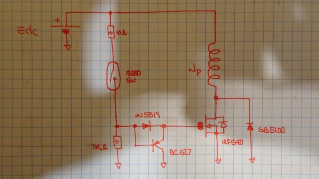
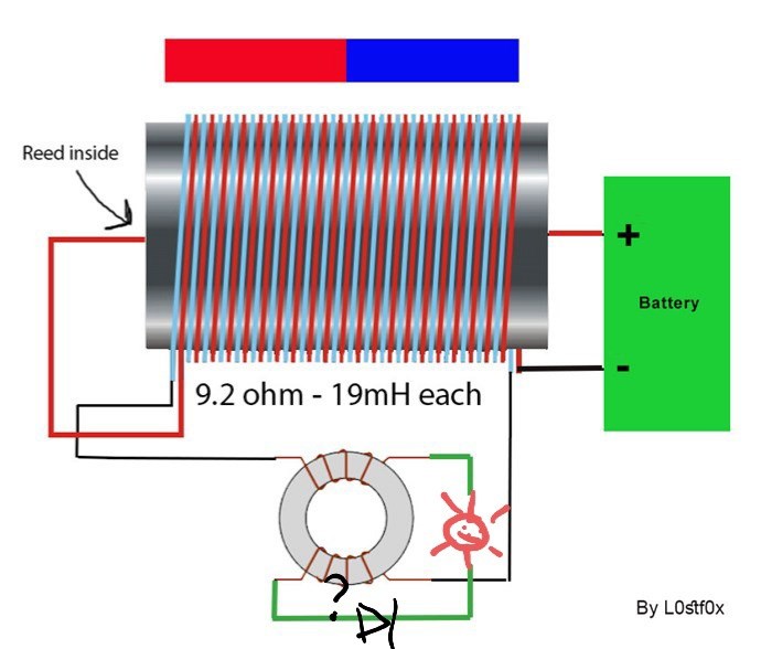
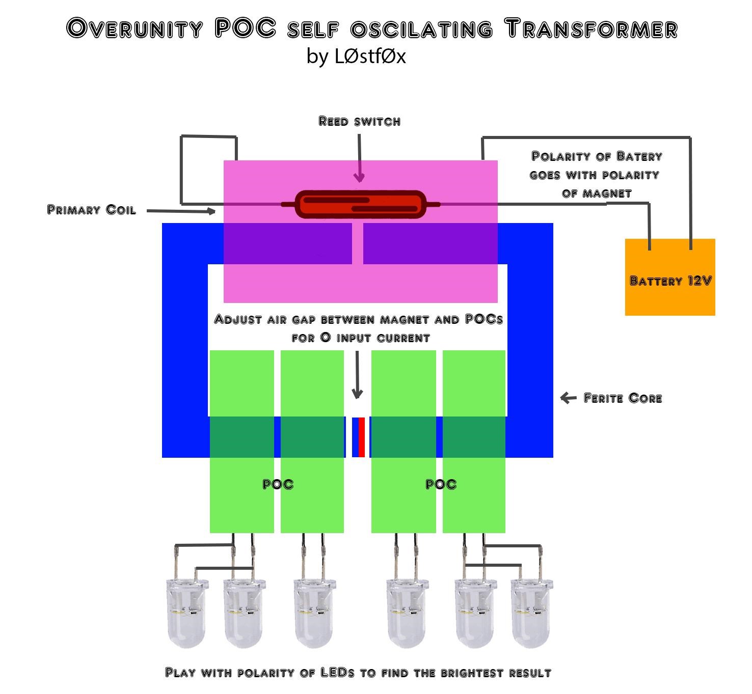
a) at what frequency does this device self-oscillate
b) what type magnet is used
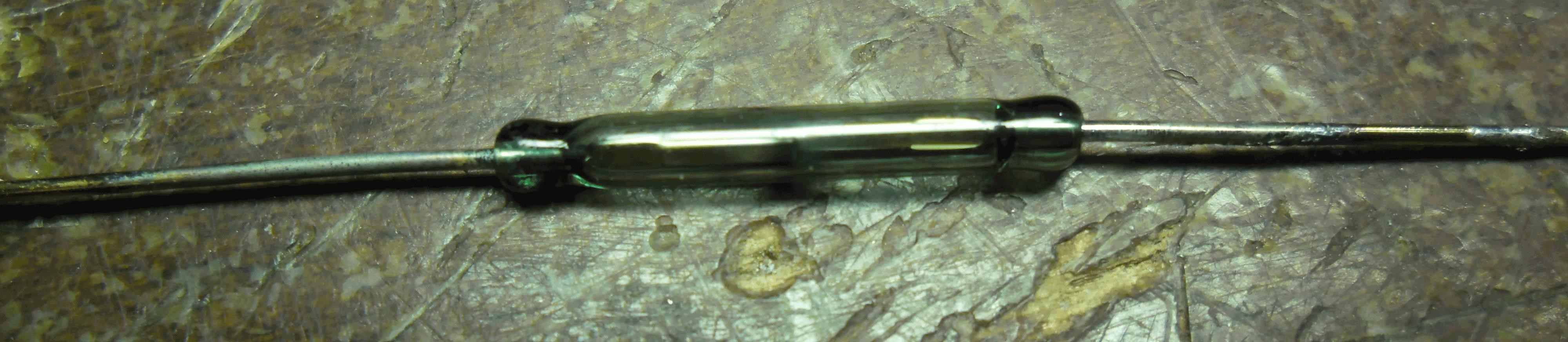
c) whether the reed switch deteriorates much during prolonged use
d) bucking vs non-bucking coil performance
e) number of windings
f) effects of increasing load, e.g., frequency shift
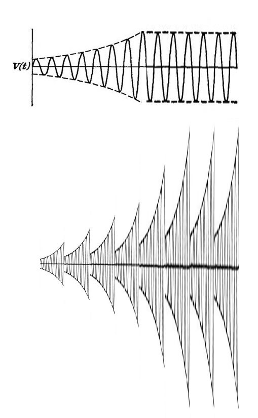
g) some waveform analysis

Answers:

a) It is jump up and down, between from 2.2khz to 3.1Khz depends of the reed you use.
Usually 20 mm long reeds work in the range of 1,5K to 2KHz. Smaller reeds work much higher, 7Khz 8Khz etc.

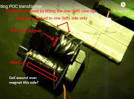
b) Magnet is a small neodymium flat disc magnet (the poles are on the two wide sides).
But as I discuss further down, any magnet will do as long as it triggers the reed switch.

c) I discuss it further down.. I believe reed will be good as new for many years as is..
No dark signs on plates, nor heat is present (the current passing it is very low).
Just a small cold plasma i guess.

d) This need testing.. I have some interesting combinations in mind..
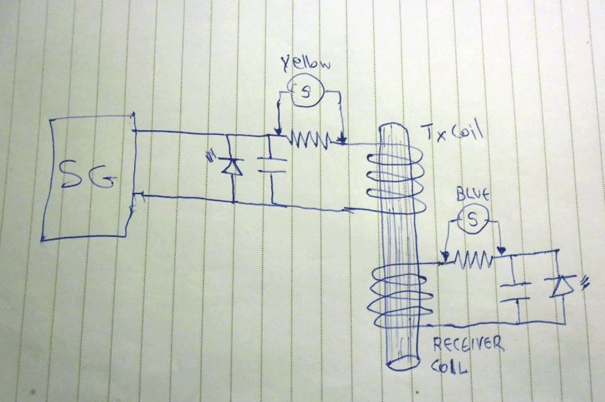
I believe at the secondary side, the two middle (side by side) coils from the four should be in POC style.

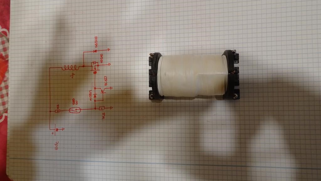
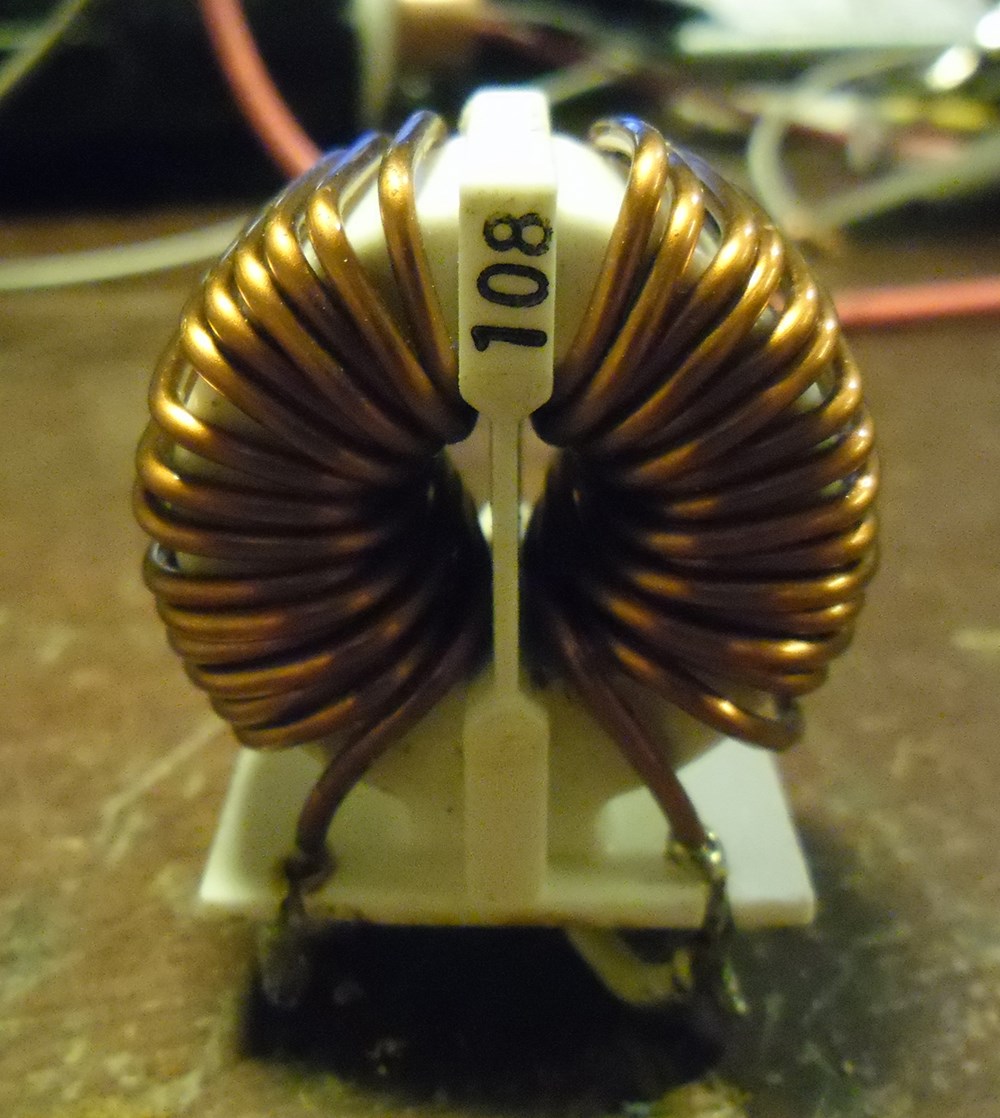
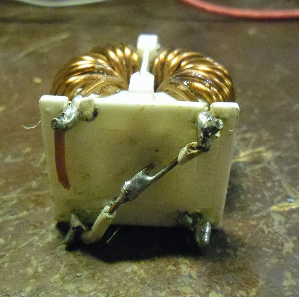
e) I haven't count any turns from any coil. I should have but I haven't sorry guys. I winded the coils only by eye calculation.
I believe turns are not important at all. Ok if you need higher voltage at output etc, but this is not the point..
Because turns alter only voltage/current relations but in conclusion there is no actual benefit from that.(I discuss it further down)

f) With stable (stable distance from reed) magnet, there is a standard output at the secondaries,
No mater if you put more leds, they will be dimmed.. put one led, it will be bright. The input current doesn't change at all.
No change at frequency when leds are in circuit or not.
Like the LEDs are invisible to primary.

g) I am sorry I don't have proper oscillator yet to see what are the waveforms! I know is like walking blind.. But thats the way it is!


Some extra thoughts:

First of all I think I understand why μA plays up and down.

That is because of frequency change. Frequency also plays between 2khz and 4khz.

Why does that happen? I think this has to be the most important question...

I can give two possible explanations..

1) Is it the reed as a component part, that because it has physicaly moving parts keep change frequency? maybe, maybe not!
(I have seen stable frequency from reed at different past similar tests)

2) Is the unequal relation of coils? (not the turns, but the wire lengths) that produce parasitic harmonics? has to be that. I believe its the coils..
I think that primary act as RF transmitting antenna, and the output coils as receiving antennas and maybe echo repeaters.

Remember Don Smith's work.. he was keep telling that length
of wires of communicating coils need to be perfectly dividable.

I believe:
straight wire = antenna
coil = antenna that due to turns triggers differently the Ether and so it is capable of producing and magnetic field as well.
So core transfers the magnetic field and coils (as wires) transfer the RF power.
The correct combination/relation of those two maybe is the key.

What you think guys?


About the input current and coils:

Sometimes the minus sign instantly gets on while it shows 0 current, this means opposite way going current? Does BEMF feed back the battery?
And if yes, Does BEMF intense/strength has to do with the communicating ability of the coils?
So maybe there is an exchange of currents going in and going out from the battery and the sum of it is displayed.

So today and tomorrow because I have time to experiment with that, as I am waiting for Monday to buy some parts for my other project.
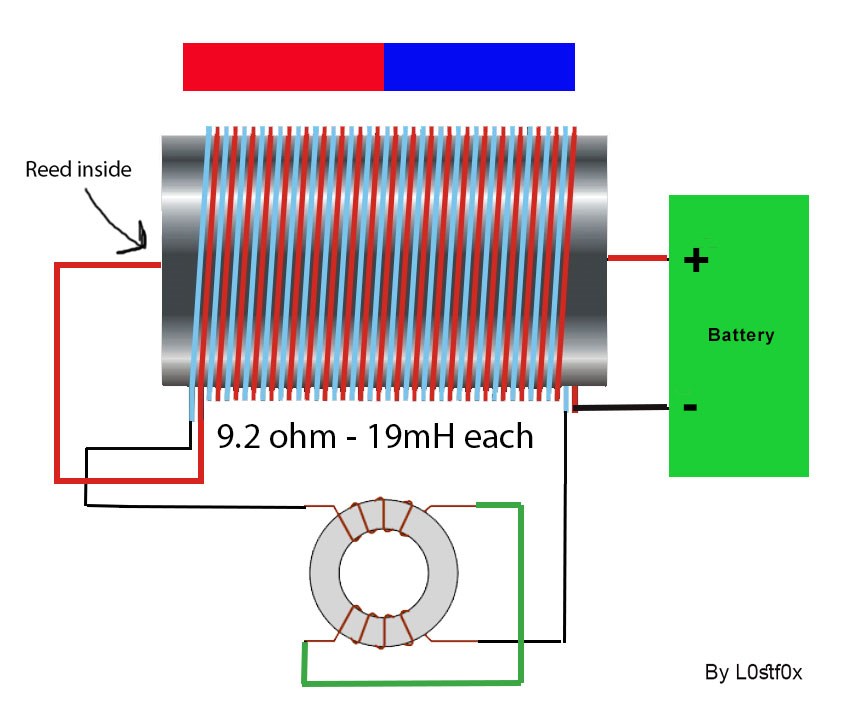
I will 3d print the spools again and make new coils.. I ll try to make all wire lengths related.
All secondaries to be equal and each one to be 1/4 the wire length of that of the length of primary.

The primary should be a coil suitable for the frequency range of reed. So no tunning capacitors will be needed.
So If anyone of you guys want to test it ...first find the primary's wire length and then divide by four to find the length of every secondary wire.

I know its not easy at all, to have equal wires. It is difficult!
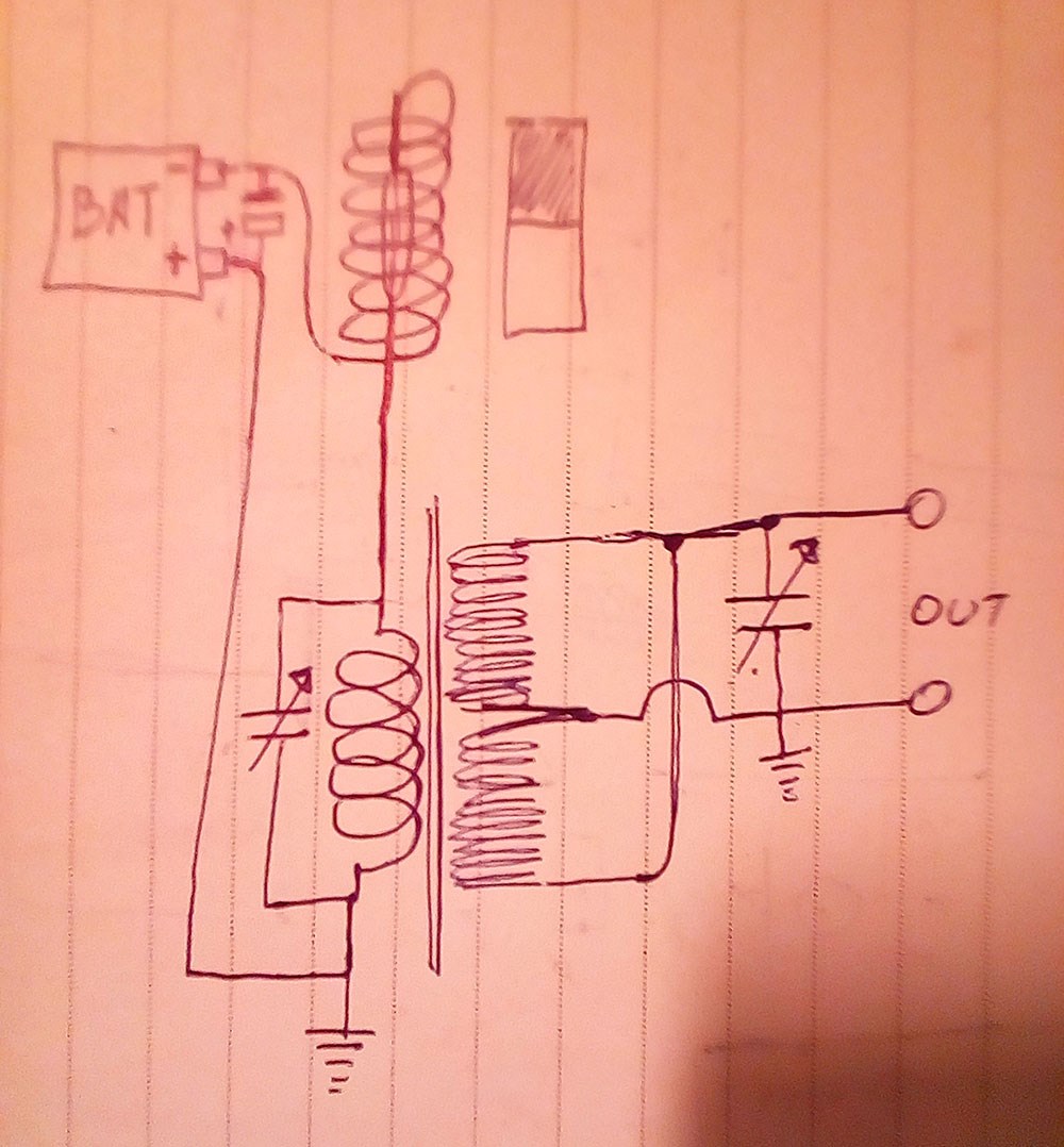

About the magnet:

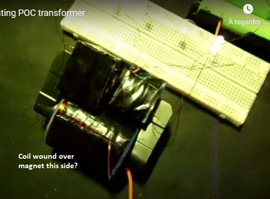
I am not happy with the magnet' s position, as it supress the normal work of the 2 close coils at its sides. and probably does harm or blocks the communication of the two core peaces.

I believe the 2 ferite core peaces should be closed/connected at secondaries side and open at primary side. Maybe I am wrong..
but I think this is the correct way.. testing needed.

In my opinion the reed will last for very very long time as long as the bias is low (magnet need to be weak not need to be strong).
Its use is just to trigger the reed. Nothing else.. Actually magnet is not wanted at all, as it acts negatively near the primary. But is inevitable to use it.
Without it you need to spent much more energy using transistor, mosfet, etc.
Keep the magnet small as possible or away as possible from transformer.. the stronger magnetic field the more current you need to spend on primary to grow opposite magnetic field to bypass magnet' s field.

So the magnet should not be where I have it... It should not interact with the core at all, I maybe wrong! I don't know yet.
it should be just above the reed, on primary's side..

Or if you extend with soft iron wire the terminals of reed far from transformer (left and right) and loop them on a magnet' s pole sides, (far from transformer) will be the best.

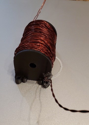
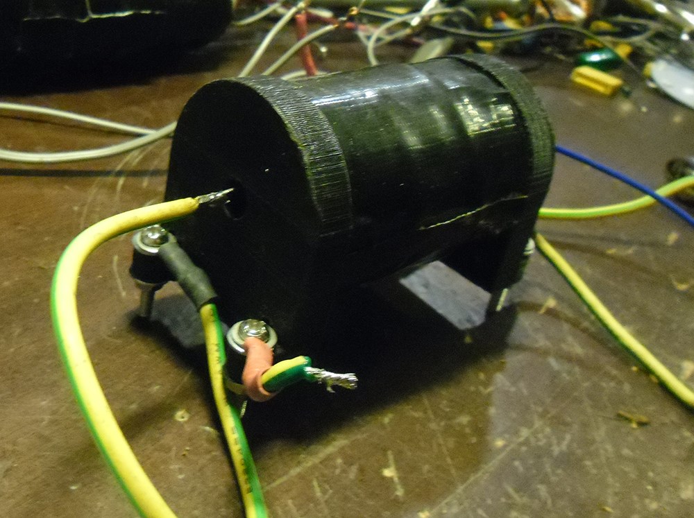
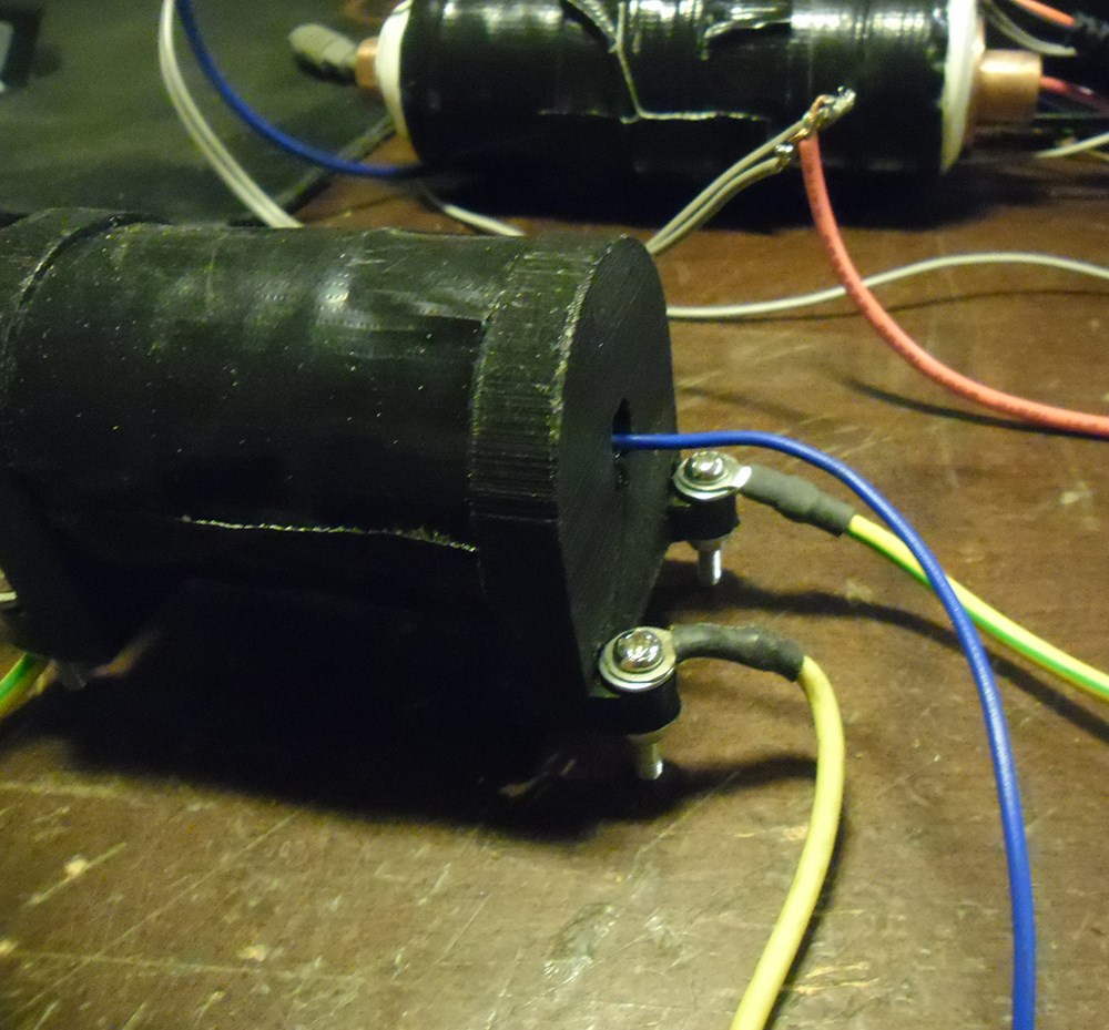
Here I made a video for you to show you details of the setup.

testing is on.. Cya all later!

Chris posted this 09 May 2020

Hey Augenblick,

Yeah I agree, needs its own Thread!

@L0stf0x, As always My Friend, Nice Work! Good to have you back with us!

Best wishes,

   Chris

Augenblick posted this 09 May 2020

Chris, could we put l0stf0x's project under a section for self-oscillating or self-resonant devices?

l0stf0x, your device is inspiring in its "dead simple"-icity.

Your hybrid schematic is clear, creative and informative.

Perhaps you could elaborate:

  • at what frequency does this device self-oscillate
  • what type magnet is used
  • whether the reed switch deteriorates much during prolonged use
  • bucking vs non-bucking coil performance
  • number of windings
  • effects of increasing load, e.g., frequency shift
  • some waveform analysis
  • et al.

This may be a great proof-of-concept tool to develop. Chris has outlined what to look for, and how to test for it. I wish you well. Thank you for sharing.

-A-

Wistiti posted this 09 May 2020

Hey my friend! I'm really happy to see you back ! Hope everything is fine on your side. Excellent work as usual it is been a while since I have play with Reed switch... On a side note I think the better place to talk about it is in your tread http://www.aboveunity.com/thread/split-positive-plasma-generator-bucking-coils-combination/?order=all#comment-926634b7-c832-4f01-8a03-aae401284598

I think it will be a great continuation of it.

Really happy to hear from you! Take care!

L0stf0x posted this 08 May 2020

Not exactly, the magnet is very small at the opening... Where you point is the reed.. here

Here also are the spools in stl files for 3d printing. You can view them in any stl editor to see how they are..

https://drive.google.com/open?id=1lBWTTR_-d1cW7-iztb2yn3xXrcApx-jJ

https://drive.google.com/open?id=125f7TPnR0vwFeVWt40oNUK7syLMsQulg


Jagau posted this 08 May 2020

Hi lostfox


Just to be sure the coil is on the magnet as in my photo ??

am i correct

jagau


L0stf0x posted this 08 May 2020

Welcome Jagau! And this is the circuit... Dead simple.

Correction! the secondary's are not connected as POC are simple dual coils. But you can connect them as POC and try different connections. I will!

Capacitors may also be useful to tune coils.. Or if you make it from beginning, it will be good idea to use equal length wires (or 1/2 etc ) for all coils. 

later guys!

Jagau posted this 08 May 2020

Ho lostfox

Excellent, for my part it is appropriate 

I would like to see the diagram when you have time

thanks for sharing


Jagau

We're Light Years Ahead!
Members Online:
What is a Scalar:

In physics, scalars are physical quantities that are unaffected by changes to a vector space basis. Scalars are often accompanied by units of measurement, as in "10 cm". Examples of scalar quantities are mass, distance, charge, volume, time, speed, and the magnitude of physical vectors in general.

You need to forget the Non-Sense that some spout with out knowing the actual Definition of the word Scalar! Some people talk absolute Bull Sh*t!

The pressure P in the formula P = pgh, pgh is a scalar that tells you the amount of this squashing force per unit area in a fluid.

A Scalar, having both direction and magnitude, can be anything! The Magnetic Field, a Charge moving, yet some Numb Nuts think it means Magic Science!

Message from God:

Hello my children. This is Yahweh, the one true Lord. You have found creation's secret. Now share it peacefully with the world.

Ref: Message from God written inside the Human Genome

God be in my head, and in my thinking.

God be in my eyes, and in my looking.

God be in my mouth, and in my speaking.

Oh, God be in my heart, and in my understanding.

Your Support:

More than anything else, your contributions to this forum are most important! We are trying to actively get all visitors involved, but we do only have a few main contributors, which are very much appreciated! If you would like to see more pages with more detailed experiments and answers, perhaps a contribution of another type maybe possible:

PayPal De-Platformed me!

They REFUSE to tell me why!

We now use Wise!

Donate
Use E-Mail: Chris at aboveunity.com

The content I am sharing is not only unique, but is changing the world as we know it! Please Support Us!

Thank You So Much!

Weeks High Earners:
The great Nikola Tesla:

Ere many generations pass, our machinery will be driven by a power obtainable at any point of the universe. This idea is not novel. Men have been led to it long ago by instinct or reason. It has been expressed in many ways, and in many places, in the history of old and new. We find it in the delightful myth of Antheus, who drives power from the earth; we find it among the subtle speculations of one of your splendid mathematicians, and in many hints and statements of thinkers of the present time. Throughout space there is energy. Is this energy static or kinetic? If static, our hopes are in vain; if kinetic - and this we know it is for certain - then it is a mere question of time when men will succeed in attaching their machinery to the very wheelwork of nature.

Experiments With Alternate Currents Of High Potential And High Frequency (February 1892).

Close