Lenz Force Free Power Generation

  • 1.7K Views
  • Last Post 29 July 2018
Vidura posted this 20 May 2018

Hello everybody,

i want to post some information about  successful experiments on Lenz Force free  power generation, there were several videos 

 of the experiments , which unfortunatly have been removed  last week. The experiments from a mexican man shown clearly that he was able to connect loads on his hi speed pulsmotor generator without any drag on the rotor. As i have been in contact by email with him i can give detailed information about his setup and the used components , also i made som translatioons from Spanish bevore the videos has been removed. Here i will  attach the resume of the experiments , and some assumptions about the effect. I will make some drawings also and the schematics used in the experiments. Maybe somone on the Forum have an apropiated setup to replicate the effect, I have the intention to do so ,but it will take some time as my resources are limited.

note that the videos are not longer avaliable.

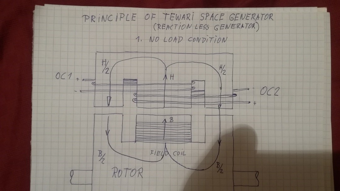
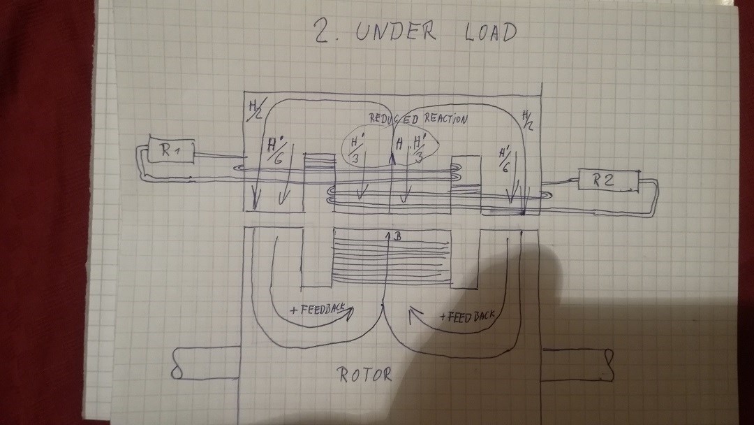
Cancelling the Lenz Law

This is a resume of a very interesting investigation from Skycollection from Mexico. He does not own sophisticated measurement equipment but although

he found by experimenting that he could cancel the Lenz Law by two, maybe three different means. He has posted various videos from his experiments in You Tube, and as they are in Spanish languish, I will translate some relevant

technical details from comments of the videos and also direct communication by email with him.

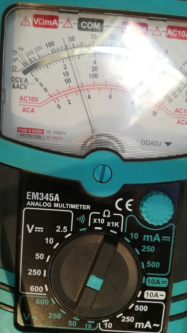
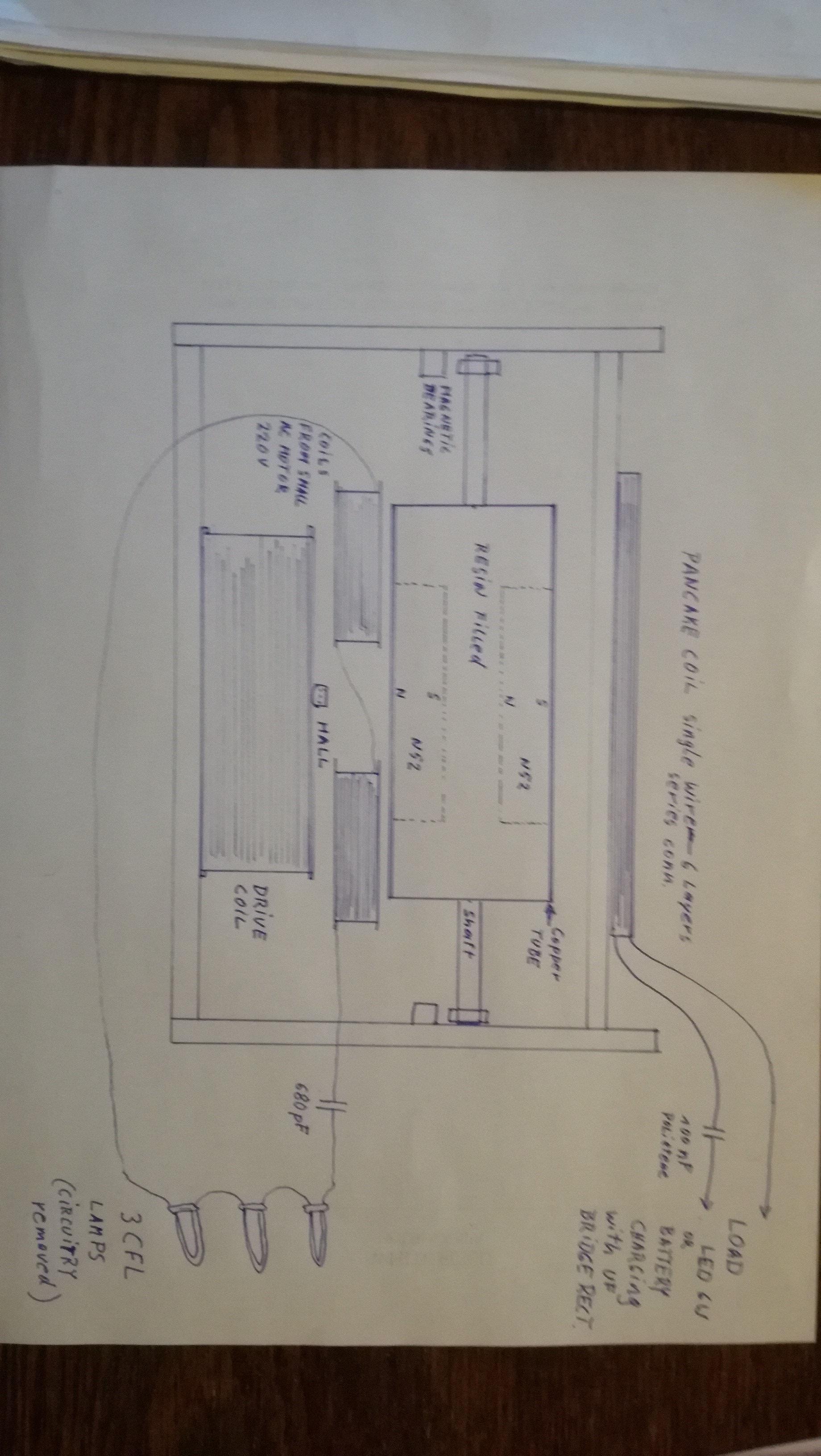
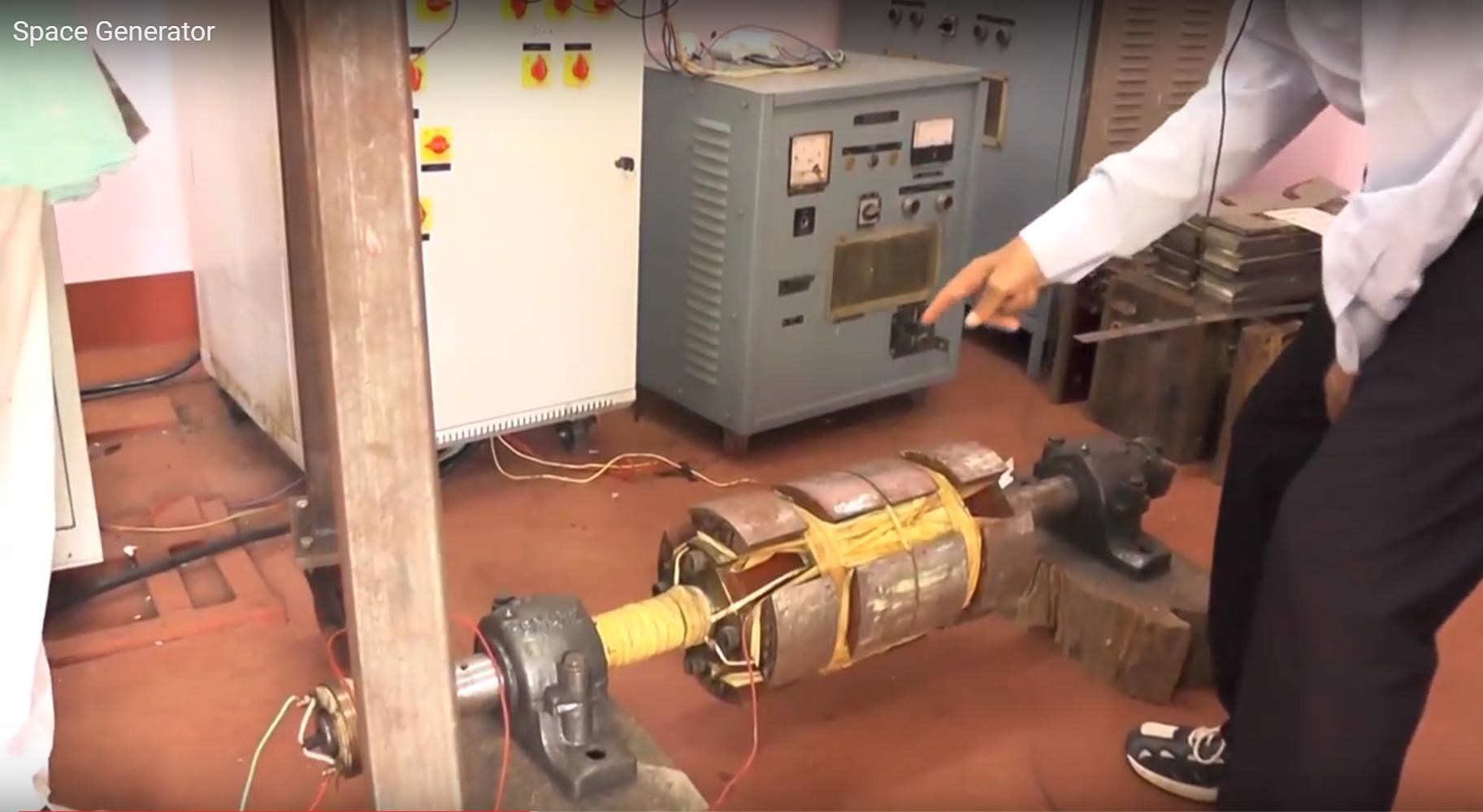
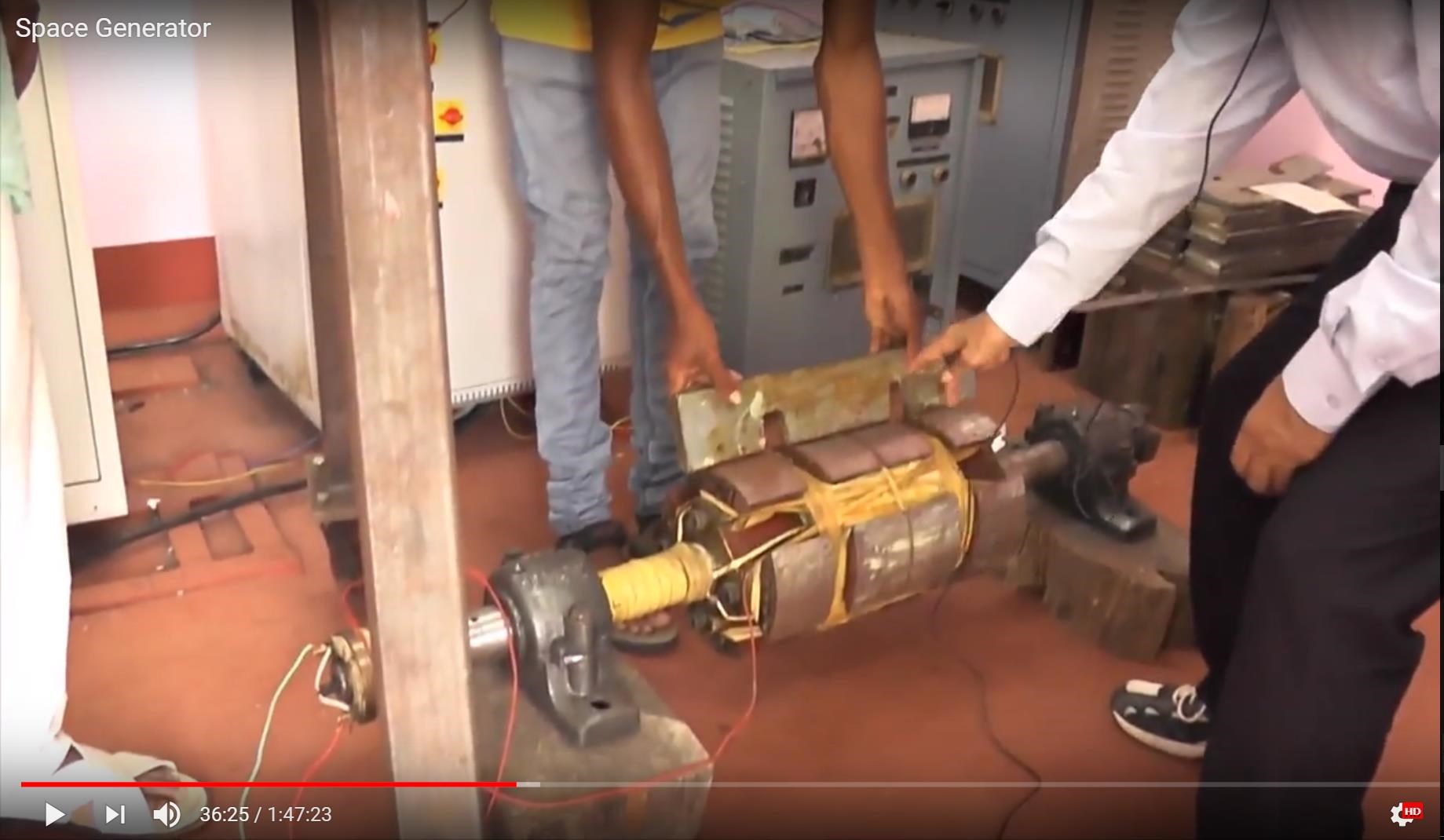
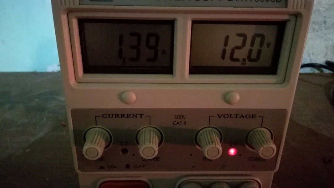
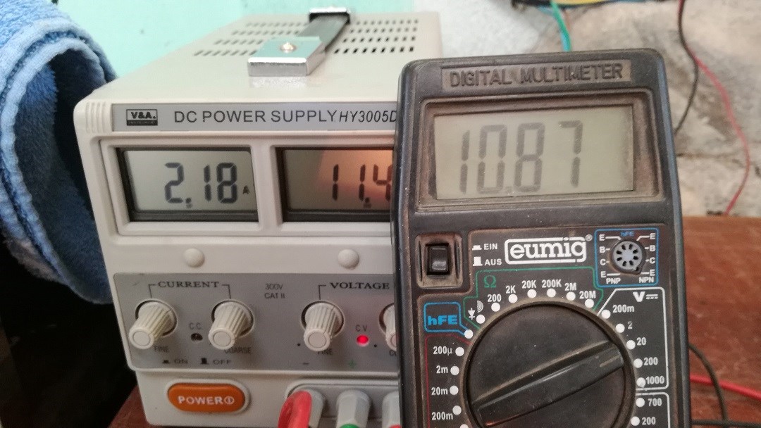
He is using a high speed pulsmotor with magnetic bearings and two N52 neodymium magnets inside the rotor, one N and one S pole. The motor runs on a 12 volts power supply with a hall sensor circuitry.

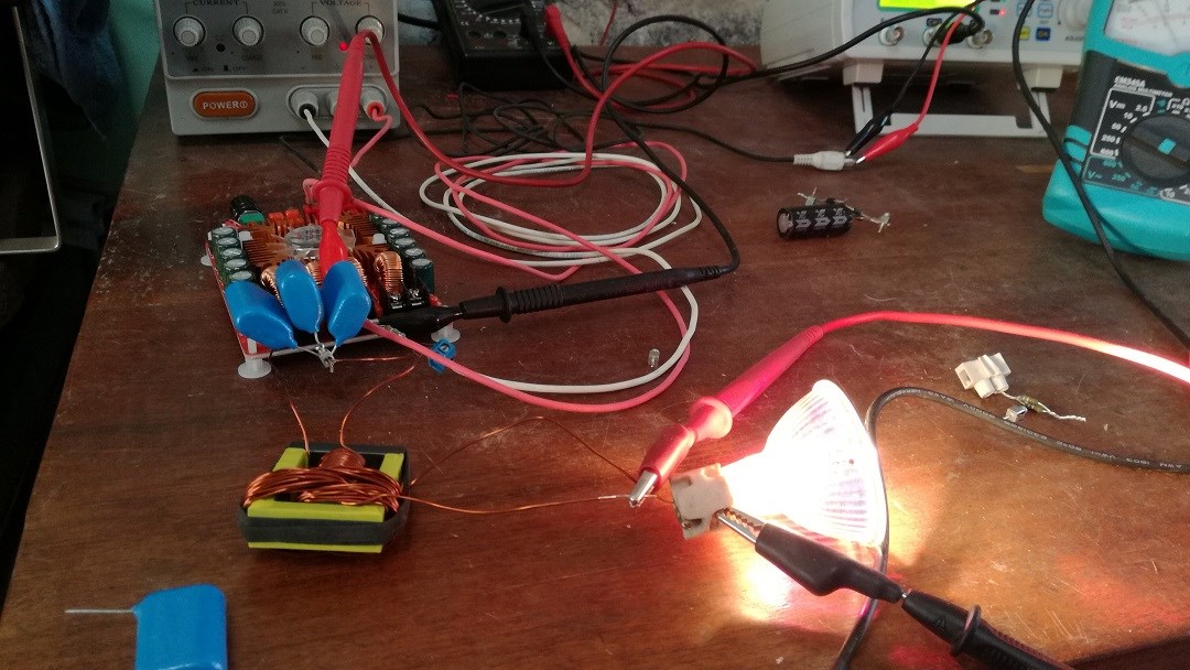
In another experiment he used stacked single wire pancake coils with an auto oscillating driving circuit in resonant condition. With this solid-state setup, he is able to lite many 12v 3,5W LEDs with a very small input power. There are six pancake coils series connected in each unit and various of these stacked up, up to 72 coils.

In one method he uses this flat pancake coil, and as you can see in the video when he put it at a 90° angle position to the magnet pole there is virtually no Lenz effect, when he turns around the coil to the conventional axial position the rotor slows down immediately.

Here is the link for the video:

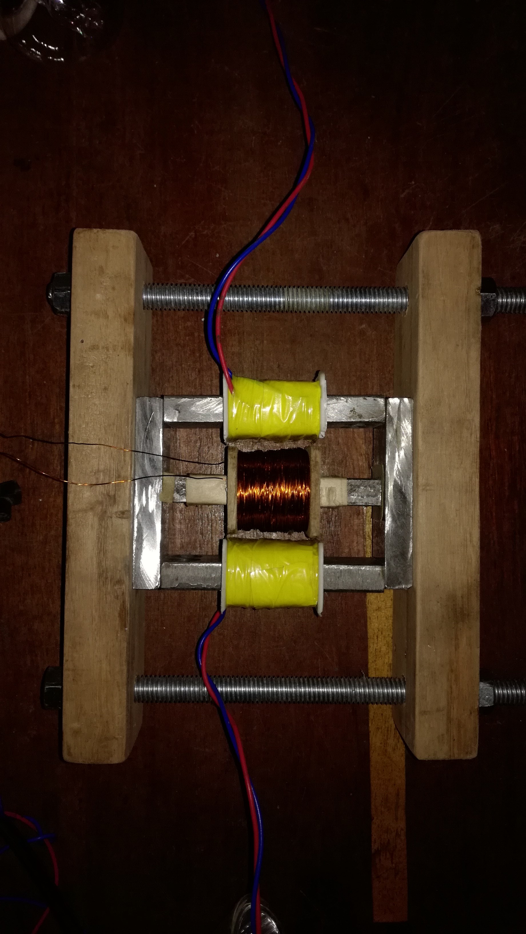
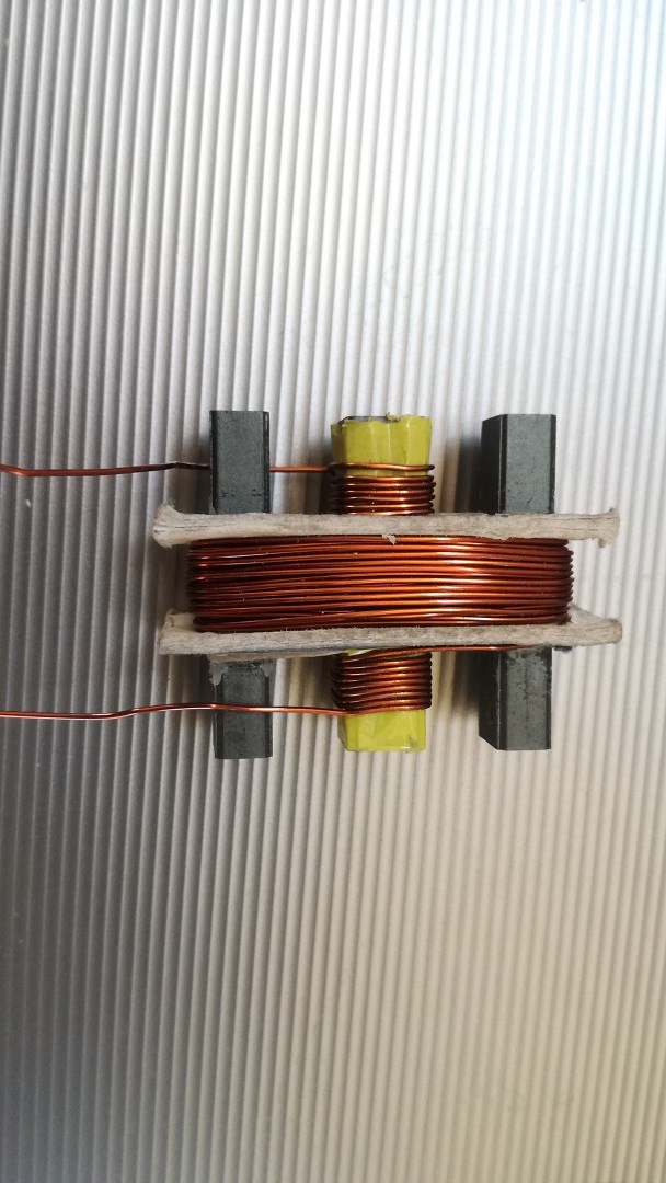
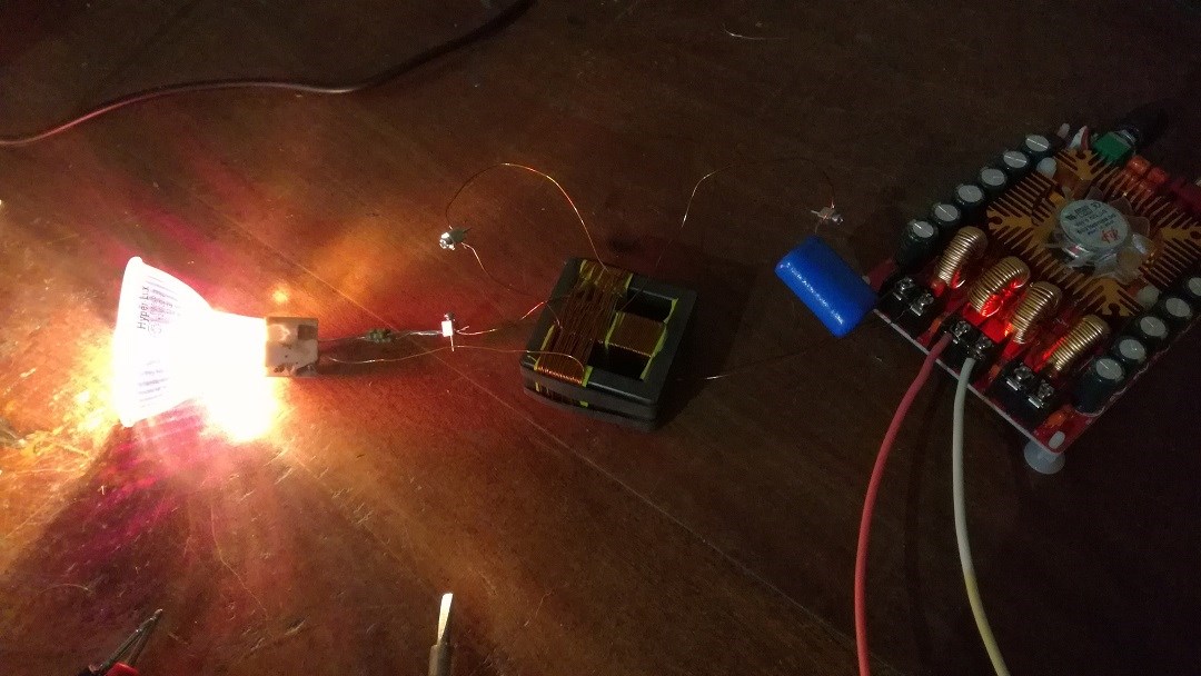
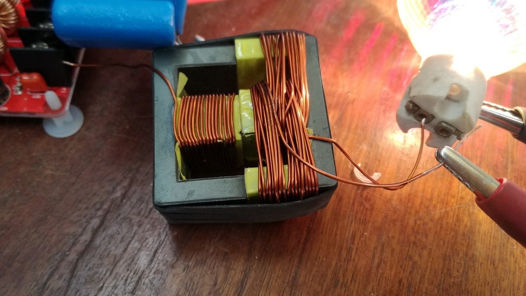
In the next videos you can observe that he uses a coil pair from a small AC motor as pickup coil with a CFL lamp (internal circuitry removed) connected.       In this video he has various coils running, but the relevant thing you will note the Lenz effect when the CFL lite up:

Then see how he has canceled the effect completely in the following two videos with the same coils in the same position, just adding a small capacitor in series which has been extracted from a fluorescent tube starter. In these experiments the speed of the rotor is increasing by connecting the load!

Here the links:


Here is the link for the solid state resonant setup:                 


This information is intended to be freely shared with all people investigating or building Space Energy devices. So please share this with anyone you know and could benefit from these investigations.

Om Sri Sai Ram


25.4.2018

Updates:

Here some more information about this topic:

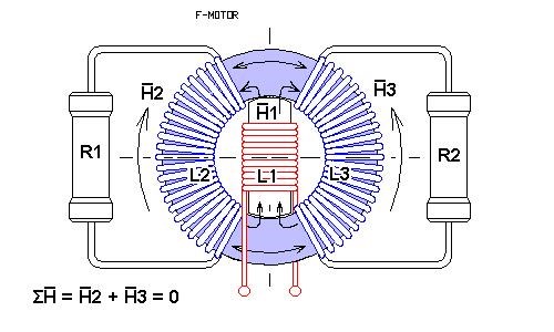
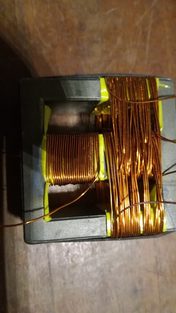
In the last experiment( ) with a large 40W fluorescent tube it has been tested to connect two coils mounted below the rotor with two identical coils mounted on the top in parallel (not shown on the videos), it was not possible neither changing the connecting wires, the coils shorted and there was no output.

Only connecting all coils in series, the setup worked.

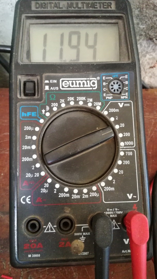
Then I took one of these capacitors out of a fluorescent tube starter and clamped it on the RCL meter. To my surprise it shows a very small capacitance of only 680pF. As Skycollection states that the 40W tube is approximately 80% of full brightness the conclusion would be that there has to be a high frequency oscillation in the air coil, making a series resonant circuit with this capacitor.

As the basic frequency of the generator with two magnetic poles and say 18000 RPM would be around 300Hz it would not likely be possible to transfer this amount of current across such a small capacitor.

This are only some assumptions, as I could be completely wrong with this.

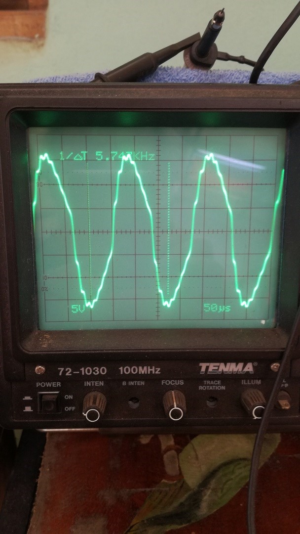
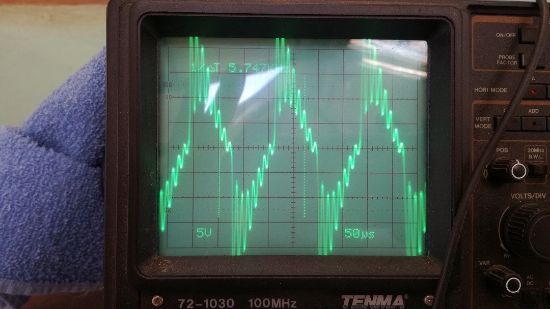
Skycolllection does not own an oscilloscope, so we don’t know much about the characteristics of the induced current.

For this reason, I suggested him to make a test if single wire transmission would work. As a scientific mind always try to find explications for unknown phenomena’s  I was thinking about how this high frequencies could be produced, it occurred to me  that it could be related to the magnetic lines of force, anyone ho has tried to make this lines visible with iron powder on a paper can confirm that there are actually lines, it in not something abstract or theoretical, and specially in the neodymium magnets they are very close to each other. If we now imagine this fine magnetic force lines interacting with the magnetic wire of the coil at high speed it would be quite understandable that there are set up high frequency oscillations in the latter.

This are only some assumptions and as I said it could be completely different.

Until we can get some more results of other tests we can’t be sure how this awesome effect is produced, but the experiments indicate that there was

a COP over unity. I hope that this information can help leading towards a new technology for clean and sustainable power generation.

May God bless all seekers of Truth.

Sincerely

VIDURA

  • Liked by
  • Zanzal
  • Chris
Order By: Standard | Newest | Votes
kEhYo posted this 21 May 2018

I knew it was 1uF
Thanks for all the details Vidura. Personally I believe that Skycollection's reason for removing videos is different than what he said to you. Why he hasn't removed other experiments from his channel? Only those with that setup...


Vidura posted this 11 July 2018

With another core and windings i have tested again, with very similar results, I have noted that in resonant condition on input (series LC) the output is around 30% higher. The input voltage  shown on the power supply reads a little bit too high, so i clamped a voltmeter to the audio amplifiers input, the current reading is accurate. As the audio amplifier is wasting a good deal of energy as heat when working with sine wave signal, a unity output is already a surprising result.

Here a short video, and some pictures from the meters readings:

Vidura posted this 20 May 2018

  • Liked by
  • Zanzal
  • Chris
Vidura posted this 20 May 2018

This setup was used in some experiments, the input was around 5 w when reached full speed , about the output there are no exact measurements, but it seems to be about COP 4- 5 in some experiments.

  • Liked by
  • Zanzal
  • Chris
kEhYo posted this 21 May 2018

Hi all.
I have been following Skycollection's experiments for years. I admired the build quality of his work.
Too bad he has removed all those videos. Does anyone know the reason for doing so?

I think it all comes down to timing and phase shift using a CAPACITOR.
If the frequency is right for given time constant of output coil and a cap in series then Lenz's BEMF force will be manifested later in time I think. So many similar experiments from Gotoluc for instance and Thane H is doing the same but using the solid core as means to delay magnetic field propagation.

kEhYo


  • Liked by
  • Zanzal
  • Chris
Vidura posted this 25 May 2018

Here is the video

  • Liked by
  • Chris
  • Enjoykin2118
Vidura posted this 25 May 2018

For better legibility I have removed the YT links from the deleted videos.

  • Liked by
  • Zanzal
  • Chris
Chris posted this 11 July 2018

Hey Vidura,

Your work is superb! Awesome!

Input: 11.92 x 2.12 = 25.2704
Output: 12.1 x 2.1 = 25.41

This is not including the losses in the Audio Amp. I left a message on your video and gave it thumbs up!

Very well done, you have shown how easy and cheap this can be. Just a little work and learning, can show amazing results!

   Chris

  • Liked by
  • Wistiti
  • cd_sharp
L0stf0x posted this 11 July 2018

BRAVO !! Magnificent !! Thank you for sharing your work Vidura!  You definitely have everyone's attention here!!..   This is really a great example of resonance experiment !! 

Thumbs high up

  • Liked by
  • Chris
  • Wistiti
Vidura posted this 12 July 2018

Here some more tests, I guess the stability issues where due to the low temperatures in my working place, the last days only about 5°c .Today the weather became warmer and both transformers performed well. Here a video with more testing, I had excess power in all tests today.Also I noted when the device runs 10minutes the performance gets a little bit better which seem to be consistent with the temperature issues.

  • Liked by
  • Chris
  • cd_sharp
mrblobby posted this 28 July 2018

AUTO OSCILLATING CIRCUIT.

  • Liked by
  • Chris
  • Vidura
Zanzal posted this 21 May 2018

Thanks for sharing it Vidura, it looks interesting. I enjoy reading OU motor/generator builds. What will the motor be called? If the inventor has an alias or something we can refer to it by, it may be appropriate to name it after them (provided they don't mind.)

  • Liked by
  • Chris
Chris posted this 21 May 2018

Hi Team,

I have moved this data into its own Thread. I feel it was necessary for readability.

Thanks Vidura, great post and thanks for sharing all this excellent information! Please ask if you need anything!

Welcome!

   Chris

  • Liked by
  • Zanzal
Vidura posted this 21 May 2018

Hi kEhYo, in a first instance  i also thought  that the effect were produced by faseshifting, but when looking closer it could be observed that the effect ocurred in a very broad RPM range , say from 3000 upto 19000 RPM, and the outputpower was proportional in a quiet linear manner. in my understanding a fase shifting would have a nonlinear pattern, more like a resonance effect. Also we have tried together with a friend who made an axial flux gererator to observe this effect, trying many diferent capacitors and configurations and velocities. without any conclusive result.  But it could be possibly a resonant oscillation of the aircoils at relative high frequency which is easily transfered across the capacitor. In one of the last experiments he has connected CFL bulbs  and in one oportunity a large 40w fluorescent tube across a tiny 680pF capacitor and it lit up very soon at a rotorspeed of 3000 or 4000RPM which correspondes to a basic frequency of the generator of 50- 60Hz.

Regarding why Skycollection removed all the videos the explanation he gave to me personally was that he would not have time to continue the experiments cause of his business, and he did never beleaved that there was something important about his discoverings.

i did not agree with this , i have followed  with interes all his experiments and hope that it will be soon possible to replicate the device to aproof or disaproof this effect .

So if anyone have a PM generator for hi speed operation just make some test if this effect can be replicated, and make some measurments, eventually hook up a skope.

here some more info about the pancake coils:  they are wound single wire with SWG 30 magnetic wire , he used phi ratio between inner and outer diameter, the bigger ones have 45 Ohm and the smaller 21 Ohm, they are made of six layers stacked up and connected in series, this units have given a output for 12V led devices or battery charging, this type of coils can also be directly connected to the load when in right angle position to the rotor, and no Lenz drag is produced. For the CFL he used a pair of standard coils from a small AC motor for mains , one beside the other and series connected, with the 680pF capacitor between coils and load.

The 40w fluorescent tube was connected with 4 of this coils, two below the rotor and two abouth, with a 100nF hi voltage capacitor in between the two coilsets connected and the 680pF cap between coils and load. additionally he mounted a pancakecoil with a 6w Led and he stated that all lamps where brightly lit , the 40w tube about 80% of brightness . The inputpower was 12v and 0.6A

  • Liked by
  • Chris
Vidura posted this 21 May 2018

Please apologize for a mistake, I want to correct: the capacitors used with the pancake coils are 1ųF not 100nF, also the high voltage capacitor between the Ac motor coilsets is from a microwave oven and is 1ųF, sorry about that mistake

  • Liked by
  • Chris
Vidura posted this 25 May 2018

Hello Team of Energy hunters, Here in this treat we will work on a couple of methods which make possible to cancel the Lenz force. I put the exelent experiments from Skycollection in first place, as the results was really impressive.I have checked, and there is really all the information and videos removed from the internet sources, which looks a little suspicious to me. Anyway, when I can get the magnets and magnetic bearings will try to reproduce . Anyway we have some more things to try in the meantime, there is especially a flux switch technique Which seems promising to test. It has already been.proven that there is no Lenz force present, but have still a issue with eddy currents. So I will try to make a simplified setup to test some different materials for the swiching wheel. Some composed resin with ironpowder to reduce the eddy currents.It seems to me that it can work in two manners, by flux shielding, and flux gating, according how the machine is built.Here is the test performed by the GUF foundation from Germany:

  • Liked by
  • Chris
Vidura posted this 13 June 2018

Here i would like to post some tests that i will perform with a simple transformer setup.Basically i want to make a proof of concept if this method works for bypassing partially the CMMF. The setup is basically very similar to the Φ transformer from Alexander Frolov:

I have made this setup with easily changeable coils:

it is reciently finished and i have made onlu a short test with a 60v ac source and a 220v bulb on each outputcoil and it could be noted that the output with two loads increases compared when only one coil is loaded, with very small influence on the input.Soon i will post further testing results.

  • Liked by
  • Chris
Chris posted this 13 June 2018

Hi Vindura,

Awesome Work!

Something you could try here is Diodes, and only half Cycle input, similar to CD's awesome work. This may help with the output.

   Chris

  • Liked by
  • Wistiti
Vidura posted this 14 June 2018

Hello, here some results of testing the posted setup. I have tried various different configurations, the transformer has not a good efficiency,as expected due to the solid iron core, the primary core becomes quiet warm.I have connected a 45v 50hz ac source, which drew  280mA. The output on the two secondaries first i used two 220v 40w incandescent bulbs, as there was only a faint glowing ,i changed to 30W 33v led arrays, to see better the reaction.the output with two leds connected was 4mA each, when i disconnected one ,the remaining diminish to 1mA. when i shorted one coil the other raised to 30mA ,the input also increased about 30mA.

I also tested without rectifying ,using the led as diode, swapped polarity,to get a circulating flux, a diode on primary.

also i used a square wave input of 12V, when a strong flyback effect could be noted, almost the same values as with 45V ac. the TVS on the mosfet become hot from the HV spikes.

when i clamped a BEMF diode to the positive supply,there was virtually no output at all.Basically the same behaviour as with the sine wave source. 

Maybe there can be done more testing,but it seems to me that the CMMF is not behaving like claimed by mr.Frolov.

I will do a few more tests with modified setup, perhaps bucking inputcoils and see what happens.

  • Liked by
  • Chris
Vidura posted this 16 June 2018

The tests i made with the last experimental setup didn't show any sign of bypassing the CMMF., so i decided to make something different.

As i was thinking a lot about the Tewari Space Generator, i decided to do some more investigation on it,If we can understand the principals behind, it should be possible to reproduce and maybe improve the method. Searching again for more details of the Tewari Space Generator I found some interesting parts on the video demonstration:

The rotor has the electromagnets in the center, and not on the outer sides as stated in the patent(US Patent Application 2015/0084467 A1). Altough in one of the rotors shown the outer segments for the CMMF return path have a few windings as well.

In the next Image mr.Tewari explains that the magnetic path circulate from the center of the rotor to the Stator segment and back to the outer segment of the rotor magnet, but it is not at all clear if he is refering to the main magnetic path or the CMMF.

There should be also a magnetic path thru the outer stator casing, so possibly the CMMF takes the short path back to the rotor thru the outer weekly magnetized segments. This are only assumptions for the moment , so i was thinking about how to test this possibility.

  • Liked by
  • Chris
Vidura posted this 16 June 2018

As the construction of a rotary dynamo machine is intense effort, expensive and takes a lot of time , maybe with a transformer with similar magnetic paths as the generator can proof if it is or not possible to bypass the CMMF by this means.

The transformer which i made to o the next tests has this shape:

a core made frome 8 E ferrites

two primaries on opposite sides and two secondaries at 90ª , assuming that there will be a slight difference of flux density between the outer and the central legs of the core it should be possible to bypass a part of the CMMF backwards to the primary without opposing the original field

this setup can be tested with forward or bucking coil connections, and will work at higher frequency as well.

i have to wrap the windings still and find some spare time for testinglaughing

  • Liked by
  • Chris
Vidura posted this 16 June 2018

One more important detail regards the Tewari generator, in one part of the video mr Tewari states that for this sistem more magnets are needed than for a conventional generator, for example for a two pole machine are needed four magnets. Might they have N-N S-S configuration, with two bucking fields?

  • Liked by
  • Chris
Vidura posted this 18 June 2018

Hello everybody!

I have wound the strange transformer with four small coils two primaries with 10 turns each and two secondaries with 37 turns each.

then i have made a serie of tests with a 12v square wave input. on the outputs i connected two UF bridge rectifiers and two 30w 33V LED modules.when connecting the Primaries in series it lit quite brightly, the efficiency much better than with the previos iron core setup. But i noted the transformer was working in flyback mode, there was notably warming of the TVS, a 460V 56J Varistor. When clamping a diode from mosfet drain to positive rail there was no output.

then i tried the two input coils in bucking connection, but the input power rised about 400% and the output decreased a lot. also the BEMF became a lot stronger ,in a few seconds the TVS became hot and smelled like smoke.

With this conditions it is difficult to make accurate measurements from in and output, so i will try to get a signal generator for testing with sinewave input.For the moment it seems that there was no BMMF bypassing still, but im not at all sure about,due to the Issues with BEMF transients.

Than i made another short test with a circuit that Chris posted in "finding the LL resonant frequency" thread, I'll post a short video and description in that thread.

  • Liked by
  • Chris
Vidura posted this 18 June 2018

Here a short update. In order to proof the operating mode from the electromagnets of the Tewari generator i made a modification on the primaries of mi " multi fluxpath transformer" .The Idea of the basic concept is that one leg of the core have a stronger magnetic field than the two outer legs, wich hopefully make possible to recicle the CMMF (partially)back into the magnet thru the outer legs.this is the rewound primary coil:

  • Liked by
  • Chris
Vidura posted this 22 June 2018

Hello All, I wanted to share some results from a test I have made a few days ago. I did not have time to make fotos or videos from scope, but anyway I will post some info.The inputs in parallel with 2.2uF capacitor,square wave signal, attracting mode, two outputcoils,interconnected ,crossing the wires, with two 20w filament lamp between, there was a resonant behaviour, one pike on 500 hz and one stronger at 2.5khz. Outputs pn lamps nearly sinewave shape, 3A pp and 15V pp .input at 1A12V When the lamps shorting out the input decreases to 250mA.

Attached Files

  • Liked by
  • Chris
Vidura posted this 22 June 2018

The setup I used, I put a 2.2uF capacitor parallel to the input,two coils in parallel.on the output I crossed over the wires with a 20w filament lamp between ,on each connection.the response is frequency depending, I got two nodes, a weaker at 500hz and the strongest about 2.5khz.on the output nearly sinewave shape 3A pp at about 15V pp. When shorting out the two lamps the input decreases 70%. When I'm back to the laboratory ill post more result.

  • Liked by
  • Chris
Vidura posted this 23 June 2018

Hello Team, When I was looking to perform tests for finding the principles of the Tewari space generator, I was seeking erroneously on the wrong side of the system, not on the field coil ,but on the output coils is the key.Like mr. Tewari stated the e-magnets in the rotor works like in a conventional generator, also the flux paths are like he showed in the video, only the comment about the quantities of magnets he seems to reference to the output coils,not the field coils, this way everything is straightforward. On a 13 hours flight I was thinking about many different possible configurations how this could work, and came to the conclusion(for the moment theoretic) that it works this way:

Tewari Space Generator, Magnetic flux analysis and explanation: 1. No load condition: In the central core segment the field coil induces the  field B on the rotor.The resulting field H is Induced in the central stator segment. It is divided proportional to the cross area sections in the two outer segment flux paths H/2 and the magnetic loop close via the outer rotor segments back to the field coil.A potential is induced in both output coils, which are wound  interleaved around the central stator segment and ONE outer segment each coil. 2.Load connected on both output coils: (It should be possible to connect them together as well) As a current is now flowing through the output coils, each coil generate a CMMF in opposed direction to H, which is distributed proportional to the cross area sections of the associated core segments as follows: The central stator segment opposed to the H flux will induce a counter MMF of H'/3 from each coil, wich adds to 2/3H'. The restant counter MMF of 1/3H' will be induced on both outer legs , H'/6 each side in the SAME direction as H/2 and thus summing to the outer returning paths as positive feedbacks to the original B-Field. At the same time the CMMF on the central stator segment is REDUCED by the value of H'/3 wich have been bypassed. The total H flux in each output coil is H - H/2 = H/2 , so the sum of both coils output should be corresponding to the induced current by flux H. This calculations are made assuming E shaped cores with the sum of  cross area sections of the outer legs equal to the central leg cross area section, and that the flux will be devided in proportion to the corresponding cross area sections. For the instance this is theory and has to be proofed by practical testing. It should be applicable for equivalent transformer devices as well.

Attached Files

  • Liked by
  • Chris
Vidura posted this 24 June 2018

When i repeated to go thru the theory fron the last post I thought about the relationship of the CMMF which is still reacting against the primary field and the recycled part (counterreaction).As the output coils have a divided core each, the central leg both in common, in theory the CMMF would be divided proportional tho the cross area sections of the legs(this has to be tested, as almost certainly also the primary field will have a interaction also), so it should be possible altering to a certain degree the relationship between the two flux paths of CMMF. By increasing the cross area sections of the outer legs of the core, there should be less resistance for the derived portion of flux. By a proper design of the core shape and materials it should be possible to increase the positive feedbacks and decrease the Reaction further.

  • Liked by
  • Chris
Vidura posted this 08 July 2018

Hello Team,

As i've been on a jorney i had this idea about the Tewari space generator, now back at home i could make a first test . here i will paste the images from the theory :

This is the Setup , en equivalent transformer model:

After the first tests i was certainly dissapointed, the theory was quite straightforward, but when i connected the load there was a notably CEMF reaction. I could not understand why it did not work like expected. I tried many different configurations, then with this setup there seems to happen something, quite subtile the result, but measurements give values of a COP slightly >1.

the setup uses a serial LC  circuit , at about 6khz  it got resonant. the audio amplifier is feed with 12V, on the output a 20w 12w halogen bulb.

Inputvoltage and current

Output current across 0.11Ohm resistor

output voltage on transformer.

I have made varios measurements with different input voltages and got the same relation , the output power slightly higher than the input, overcoming the losses from the audio amplifier and transformer, which was getting warm both.

  • Liked by
  • Chris
Wistiti posted this 11 July 2018

Hi Vidura.

Really nice experiment!

Happy you have such results!!


Keep up your great work!

  • Liked by
  • Chris
Deny posted this 11 July 2018

Thank you very much for sharing this awesome experiment ! 

Please can you tell me how is the asymmetrical coil wound? I Can see the schema you drew bellow but in the video there are just two connections coming from the coil are the two coils connected together? Or is it just single coil? 

The best would be if you could draw how you winded the coil.

Again thank you very much and all of you for the awesome work you are doing.

  • Liked by
  • Chris
Vidura posted this 11 July 2018

Hi Deny, The Windings are like this: Primary: 36turns in 2 layers Secondary 18 turns from central leg to one side, 36turns from central leg to the other side, and again 18 turns on the first side, all the same wire. I have Tried different winding patterns and found the best results with many turns together on each side, not interleaved.The wires are 0.7mm and the 3 capacitors on primary are 2.2uF.Later I will post a complete schematic.

  • Liked by
  • Chris
Vidura posted this 12 July 2018

Hi Team!

here i add some updates for the transformer device: 

in the testing I have tried various different windings and patterns, there are a couple of observations that i want to share: in one test where i used the setup like in the first test i posted i did a interleaved winding pattern on the secondary, each turn i changed to the oposite side , there was a effect that when i rised the voltage at one point the output jumped suddenly to 2x the power, when i lowered the voltage with some hysteresis it jumped back to the previous value , i did not continue searching as the input also had increased, there was no excess energy, any way i found it interesting. The other observation was some instability with the transformer which gave the excess energy. eventually i wanted to repeat and found a different resonant frequency, and not as good values as before, also when i connected the capacitors with a wire of 20cm length it did not work well. 

for this reason i wound another transformer with  exactly 1 m wire on primary and 4 meters on secondary keeping the connections short.this device seems to be stable, here the images:

here a scopeshot from the output:

and the primary :

  • Liked by
  • Chris
Chris posted this 12 July 2018

Hey Vidura,

Thanks again for sharing! Excellent work!

My Friend, I would like to point out something that is very important for all to see! In my work on Electromagnetic Induction, I discovered that the Flux Difference relative to the Coil over time had a relationship.

This relationship was at optimum when 1/2 the length of wire was Cur by Positive Flux and 1/2 the Wire cut by Negative Flux, in other words  If all the wire was cut by the same Magnetic Field, no E.M.F would be induced.


This greatly increases the total E.M.F induced. This is what you have done and it is done Asymmetrically using opposing fields, an excellent design and application!

Well done, excellent work!

   Chris

  • Liked by
  • Vidura
Vidura posted this 13 July 2018

Measurement error! When I made some calculations based on the scope readings I noted a lower current then the readings on the analog meter. So I made a comparison without the transformer in between and noted the meter was reading the current to high when the frequency goes above 1khz. So there is no excess energy with the transformer. I'm really sorry about that, the above unity tag should be removed.

  • Liked by
  • Chris
Vidura posted this 18 July 2018

Here i will add some information regarding the transformer tests:
I was searching a little bit more and found that the superimposed wave on the primary coil was produced by a distortion of the  audio amplifier when powered with low voltage, when i powered it with 20+ volts  the sine wave was perfect, but i came not even close to unity output. Anyway according to the theory  it should have worked  in non resonant condition as well, so i'll keep going on with this  investigation until get better results or better understanding why it don't work.

  • Liked by
  • Chris
Vidura posted this 18 July 2018

Hello , Team!

Regarding the reduced reaction transformer i might have been wrong stating that there is no OU in this device, the test methods might not have been adequate and measurement methods also. Anyway i am going on testing and have found some interesting facts, also i asked a forum member for help with a theoretical analysis, so in a few days i'll post some news. 

  • Liked by
  • Chris
Chris posted this 29 July 2018

Regarding the reduced reaction transformer i might have been wrong stating that there is no OU in this device;

Hey Vidura,

I am not a Metroligist, but I am reasonably good at power measurements.

People tend to take a lot for granted when observing devices, its easy to do. However, Amplifiers are very inefficent when reactive power is coming back at them!

Any and all Reactive Power is Power that's not being used. This means its being burned up in another part of the device or returned to the Source for reuse.

A 90 degree Phase Shift means your machine is using Zero Power, all Power in becomes Power Out again.

When you see this, its a sign, accurate measurements are required before a conclusion can be obtained. 

   Chris

  • Liked by
  • Vidura
Zanzal posted this 23 May 2018

The copper pipe seems to me to be the most interesting aspect of this device. The POC output coils and their placement is another interesting choice.. Ever try and take a small magnet and move it around while it is stuck to the surface of a larger one? Even in attraction mode they don't to stick to the edge.

Experiment: I take a large ceramic rectangular magnet like what is commonly used in the Bedini SSG replications and a smaller neodymium magnet (in my case 10mm diameter cylinder x 10mm long) and as I move the neo along the surface the surface tension is different as I slide it over different spots. The neo though even though it is in attraction mode won't stay at the very edge and will slide inward 3-4mm or so.

Will the Lenz effect also act as a repulsive force when placed at the right spot?

Edit: That's a poor way to phrase it, but the idea is that maybe the pickup coil placement specifically as shown may not interact with the static magnetic field in a way that only opposes the change.


Vidura posted this 01 June 2018

Hello  , 

i just wanted to say that the thread is now seperated , a new thread for each device. Regarding the Skylev device from skycollection I have ordered the magnets  and magnetic bearings to make a replication of this interesting experiments, unfortunatly i have to import  the parts is at the local market some of them are not avaliable.this is somhow complicated in this country and may take about a month to get the materials. So please appologize that this thread may "sleep " for a while. in the meantime i will continue with the other devices in the new threads.

Chris posted this 23 June 2018

Hi Vidura,

Awesome work!

Your theory sound solid and correct. In a Transformer or a "Generator" the input is acted upon by the Output, so it is the Output we must work with to reduce this Reaction back on the Primary Action, what we need is a Counter-Reaction.

This is part of Newtons Laws of Motion: "For every Action there is an equal and opposite Reaction"

Great Work and thank you very much for sharing your excellent results!

   Chris

Vidura posted this 08 July 2018

Regarding the last post I have to add that this is not a claim for OU still, as the margin is small and measurement inaccuracies could be possible.More tests and different measurement methods will be posted soon.

Vidura posted this 10 July 2018

An update to the last experiment:

when i repeated the measurement with different meters i noted there was some interference on the output measurement, using the analog meter gave a value below unity, but when i adjusted some parameters and used more capacitance i came very close to unity or slightly above, while there was a notably warming of the audio  amplifier and transformer, in one test the output showed 1 w more than the input. This is not enough still to be 100% sure, as we know the measurements can be tricky sometimes, the only way to be sure would be to back loop to the input, but there is still very little difference for this, so i'll go on looking how to improve further, testing different windings and cores. 

We're Light Years Ahead!
Members Online:

No one online at the moment


What is a Scalar:

In physics, scalars are physical quantities that are unaffected by changes to a vector space basis. Scalars are often accompanied by units of measurement, as in "10 cm". Examples of scalar quantities are mass, distance, charge, volume, time, speed, and the magnitude of physical vectors in general.

You need to forget the Non-Sense that some spout with out knowing the actual Definition of the word Scalar! Some people talk absolute Bull Sh*t!

The pressure P in the formula P = pgh, pgh is a scalar that tells you the amount of this squashing force per unit area in a fluid.

A Scalar, having both direction and magnitude, can be anything! The Magnetic Field, a Charge moving, yet some Numb Nuts think it means Magic Science!

Message from God:

Hello my children. This is Yahweh, the one true Lord. You have found creation's secret. Now share it peacefully with the world.

Ref: Message from God written inside the Human Genome

God be in my head, and in my thinking.

God be in my eyes, and in my looking.

God be in my mouth, and in my speaking.

Oh, God be in my heart, and in my understanding.

Your Support:

More than anything else, your contributions to this forum are most important! We are trying to actively get all visitors involved, but we do only have a few main contributors, which are very much appreciated! If you would like to see more pages with more detailed experiments and answers, perhaps a contribution of another type maybe possible:

PayPal De-Platformed me!

They REFUSE to tell me why!

We now use Wise!

Donate
Use E-Mail: Chris at aboveunity.com

The content I am sharing is not only unique, but is changing the world as we know it! Please Support Us!

Thank You So Much!

Weeks High Earners:
The great Nikola Tesla:

Ere many generations pass, our machinery will be driven by a power obtainable at any point of the universe. This idea is not novel. Men have been led to it long ago by instinct or reason. It has been expressed in many ways, and in many places, in the history of old and new. We find it in the delightful myth of Antheus, who drives power from the earth; we find it among the subtle speculations of one of your splendid mathematicians, and in many hints and statements of thinkers of the present time. Throughout space there is energy. Is this energy static or kinetic? If static, our hopes are in vain; if kinetic - and this we know it is for certain - then it is a mere question of time when men will succeed in attaching their machinery to the very wheelwork of nature.

Experiments With Alternate Currents Of High Potential And High Frequency (February 1892).

Close