Let's Sparking ...

  • 2.7K Views
  • Last Post 19 February 2019
alohalaoha posted this 08 December 2018

Ok folks

Let's sparking...

But what ?

Let's sparking partnered coils

But what are in fact partnered coils ?

Transmission line, Short circuited transmission line, shortly SCTL.

Why ?

Because there are hidden under the 7 locks aboveunity current and voltage amplifications.

As in Russia said: "All new is long time forgotten old".

Same Anomaly Pulse exist when you used mosfet instead spark gap. This should work also with bipolar transistor, tyristor or igbt.

Next step is organising smart way power extraction, using λ/4 voltage amplification or λ/2 current amplification or both in the same time using additional pair of partnered coils, each with their own respective lenght.

Let's think about the most smartest way to take all Ether power for our needs.

Count-1

Attached Files

  • Liked by
  • Chris
  • Vidura
Order By: Standard | Newest | Votes
alohalaoha posted this 08 December 2018

The short circuited transmission line behaves as series resonant circuit at the short circuited end because the maximum flow of current take place at the short circuited end.

At λ/8 away from the shorted end, towards the source, the behavior at this point will be inductive.

This behavior will repeat at 5λ/8 from the short circuited end.

At λ/4 from the short circuited point of transmission line, the circuit will behave as parallel resonant circuit.

It is due to the reason that at point the current is maximum possible.

At 3λ/8 form the shorting end the behavior will be capacitve.

This behavior will repeat at 7λ/8 and so on.

The behavior of short circuited transmission line as a series resonant circuit or parallel resonant circuit or inductive or capacitive circuit will repeat it self in the same manner toward the source at each λ/2 intervals if the transmission line is long enough.

Count-3

alohalaoha posted this 08 December 2018

Why this is needed ?

Because we need to find exact wire lenght of sort circuited transmission line including velocity factor of our impulse or we need exact wire lenght of partnered coils where the magic will start on.

It means if we want current amplification effect while sparking, we need to make partnered coils lenght exactly at λ/2 or even multiple of λ/2.

If we want voltage amplification effect while sparking, we need to make partnered coils lenght exactly at λ/4 or odd multiple of λ/4.

For maximum power extraction from partnered bifilar at his resonant point, load resistance MUST be the same as partnered bifilar impendance (wave resistance).

Anomaly Effect is a strictly wire lenght dependent so we must care attention for each mm lenght error.

The most precise way to measure wire lenght and characteristic bifilar impendance is using an oscillograph and TDR or Time Domain Reflecometry. Who has vector signal analyser can do it on most easiest way. Simply tune S21 parameter to active resistance value canceling imaginary part of S21 coefficient (tunning line lenght), so the coefficient remain matched with load only with real part.

Light Up the Mind Darkness !!!!

POWER TO THE PEOPLE !!!!

Best wishes

ALOHA

RUSSIA

Chris posted this 09 December 2018

My Friends,

We must realise, Don Smiths Output Circuit holds some similarity's:


This basic Circuit design is not that uncommon:


Ref: Sine Wave from a Square Wave


   Chris

alohalaoha posted this 09 December 2018

Thank you Chris

Yes very similar concept. I know Don Smith had knew about interaction between magnetic fields (stationary and dynamic) and stationary and dynamic charges.

If you charge two light bodies suspended on insulating silk threads, touching them with a glass rod rubbed against silk, then both bodies repel each other. The same is observed if both bodies are charged with the help of an ebonite stick, worn on fur.

But if you charge one of the bodies from a glass rod, and the other from ebony, then both bodies attract each other !!

This is a fact which anybody can check !!

This means that the charges of glass and charges of the ebonite differ in quality. Despite the abundance of various substances in nature, there exist are only two kinds of electric charges:

  1. charges similar to those that appear on glass, worn out on silk, and
  2. charges, similar to those that appear on ebonite, worn out on fur.

The first of them are (wrongly) called positive charges, and the second - (wrongly) called negative charges.

Consequently, like charges repel each other, while opposite charges attract each other. This phenomenon of electrostatic  repulsion had been used by Russian academicians M. V. Lomonosov and G. V. Richman for making their device - an electroscope.

So when you bring a charged body to an uncharged electroscope, you can see that the electroscope's leaflets are deflected even before the body touches the electroscope. This is a 1st fact

If the electroscope is precharged, then when the body of the same charged body is presented by it, the leaflets are deflected more strongly. This is a 2nd fact.

If the body has a charge of the opposite sign (wrong formulation), then the deviation of the leaflets decreases as the body approaches, and then, after passing through zero, it increases again. This is 3rd fact.

But how to explain this facts. There is no full or partial anihilation of charges, no sparks, no arcs or anything similar but in my oppinion only charge's balance instability. This bring me to concluion that there exist not two charges, but one substance - one charge in different saturation phases.

Deviation of charges means balance of fully saturated charges and unsatuarted chares. In some moment of time, in some special position where the both charges balance their quality, we have full charged electrostatic balance - full electrostatic quilibrium, but we have no charge anihilation. Further when we bring charges in the much closest proximity, leaflets are again deflected but this time more strongly. It means we have over saturated electroscope rod with same kind of charges.

This is a simple logical explanation i could contemplate.

All of these show us that charges appear on the conductor (an electroscope rod) already when a charged body is present nearby, under the influence of this body.

Therefore, the described phenomenon has received the name of electrification by means of influence or electrostatic induction, and the resulting charges are called induced. The phenomenon of electrostatic induction was studied in detail in the 18 century by Russian academician Epinus.

Stationary magnetic field (magnetic N-S dipole) from ordinary neodymium magnet has ability to ATTRACT charges of both electrostatic phases (satuarted and unsaturated) while we bring him in the close proximity eiher with N or either with his S pole. So there exist electrostatic force when you bring magnet near precharged bodies suspended on insulating therad.

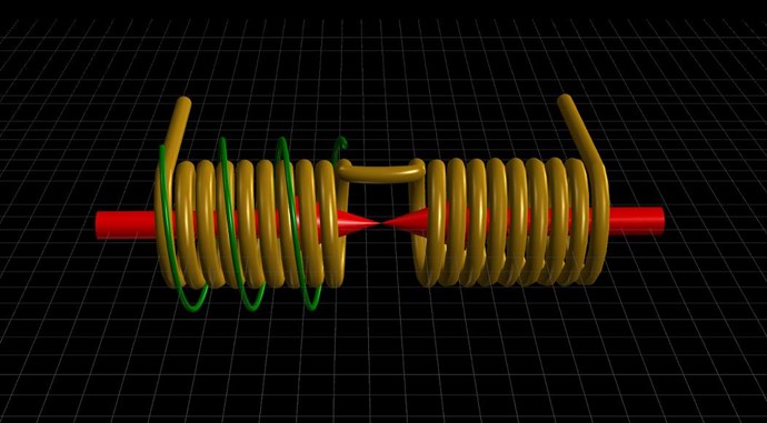
If all of these facts worth for stationary charges and stationary mag.field (magnet), there is no reason why this shoud not work with dynamic charges (charges in motion) and dynamic magnetic field (magnet or solenoid in motion).

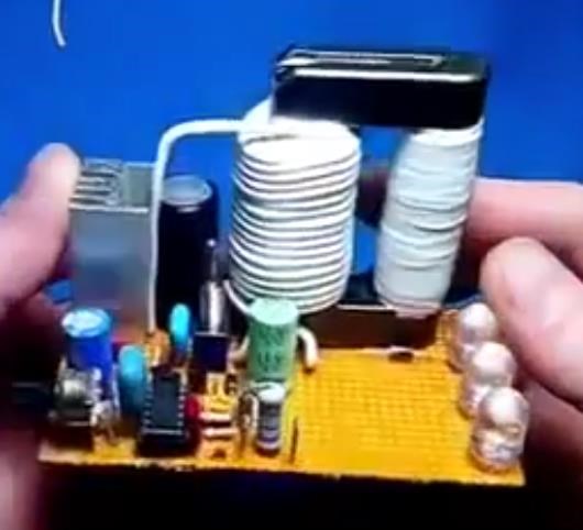
Now remain to use explanied concept in design of free energy generator.

Regads

Aloha

Prometheus posted this 10 December 2018

First voltage maximum node is at λ/4 away from the shorted end towards the source.

Current is minimum and voltage is maximum at λ/4 distance from the short circuited end.

Current is maximum and voltage is minimum at the short circuited end.

Have you tried output coils at the λ/4 antinodes, and diodes connected to ground at the corresponding nodes to pull electrons in from ground and trap them in the circuit?

alohalaoha posted this 10 December 2018

Hey Aloha,

your posts are very interesting, and your understanding of russian languish gives you acess to many valuous documents  and investigations from this country. Keep it up, we cant expect anything from others, but the knowledge and experience we are achiving will change the future  certainly. 

Regards Vidura.

Thank you for your support Vidura, also thanks to all other guys here. I know you are good and honest people. Also you have very extraordiary interesting ideas and thoughts. Yes I am ordinary russian guy, and my goal in this field is only one. Examine, research and bring the people Free Energy even in form of electricity or in form of heat. I am speaking and writing several languages and i am serching and analysing everything interesting which i can find in public internet. As always i havent learned all the Etheric wisdom from this and upper realms, but I give my best because i know we are playing in several realms in parallel. Final result depend from it how we can give a best of our abilities, becuse every our action in this realm imply reaction in upper realms. We are currently playing here in last realm 7th. Does anybody could answer - why we are using here (in this reallity) only 5% or less of all our mind and intelectual abilities ? Very hard question for anybody who want to be honest with yourself.

I know our biggest problem is not lack of creative ideas and thoughts, but in 99% cash. As i have said earlier, you could get a free launch on many places, but no way to get free experiment in form how you have created them in your mind.

Only way to touch a truth is his majesty Experiment. Becuse he has  always telling us a truth in all possible and impossible circumstances.

So he is our GURU. Except him there is no one in the whole Ether infinity, who can show us a right way. Every experiment in this realm (life here is also experiment), play important role in upper realms where our partitioned consciousness PLAY THE LIFE GAME in parallel with this one, for our final freedom. Body and soul are matrix's chains, but our consciousness is our essence, our being. Simply said using Artic Vedas FIRE OF AR (primary life force spark) which rule in the abyss of infinite Etheric realms.

Best wishes to all

Aloha

alohalaoha posted this 14 December 2018

solarlab posted this 30 January 2019

Hi Aloha,

Just a quick note to thank you for sharing your insights regarding some of your topics (ideas) discussed in this thread.

Since I have a working device (unstable however), but can not fully understand why or how it works at the moment; it is still impossible to completely explain it, optimize it, or properly develop it further. Therefore unverified postulations, observations or theories, at least from my prospective, are more than welcome!

I've put together a general understanding of how it appears to operate, and why it does what it does, but thats the extent of it. A majority of the underlying physics is still a work-in-progress.

The device is, for the most part, a Ruslan type generator - his older designs with Tesla Antenna.

Anyway, thanks again and have a good day! I enjoy reading your posts, quite informative and thought provoking for the most part!

SL


anothercat posted this 31 January 2019

Hi everyone,

I'm not online often (and posting even less) but this topic is in my interest area so I decided to jump in.
First let me say that it is been years that I'm working on replicating/understanding the Kapanadze, Akula, Smith, Barbosa mystery. I'm feeling deep down that it is all the same thing. Difference processes, but same phenomenon. 

For me, it's simple as what Smith said (it's not the exact quotation but I guess it is close to): "Electricity is the two side of the same coin (magnetism and dielectric), you just need to know how to flip them. Pull them apart and bring them back together and you have all what you need".

And from all the inventor mentioned earlier, I see common elements/phenomenons.

  1. Strong alternating current (at least a couple of amps - in some video of Kapanadze, Barbosa and others you can hear the humming sound of a transfo or you can validate it with the push/pull yolk circuit of Akula). It can be low voltage. Potential is not important here
  2. HV resonant that need to be in phase with the alternating current mentioned in #1
  3. Capacitive coupling arrangement to merge the HV line (#2) to the current (#1)
  4. A earth ground (or a virtual ground: big mass of metal) to help attracting/exciting the capacitive coupling
  5. A spark can be added to the hv line. It probably help to stimulate the capacitive coupling or even increasing the effect. But we saw with Akula and others that this step can be optional depending on how the system is built.
  6. You tap in the middle of these reunited current+voltage lines.
  7. That's it.

I do not have the experience that some here have concerning radio frequency science, deep fundamentals , etc.. I'm just a self learner. And even if I have months on the bench trying it, I'm still not there -yet.

  • I'm able to do capacitive ground coupling with HV tesla coil.
  • I'm able to produce strong current (100amps) with less than 4 watts
  • But I'm a disaster in calculating LCR circuit and build a circuit to phase shift my 2 circuits.

After so many theories/tests on the working principles of these machines, it's the first time that I'm feeling that I'm on solid ground. I guess that patience and focus is the way to go.

I'm curious to know your thoughts about my views on this. I read somewhere that Kapanadze itself said once that if someone would know how simple is his system, this person will laugh. Could it be simple like that?

Cheers.


Zanzal posted this 01 February 2019

Thank you for your replies.

Zanzal, would you say that it's a good start for me to learn more about impedance matching, node and anti-node, etc... with this channel? : https://www.youtube.com/channel/UCop2ybGsiTYo1iyttgjNo8g

Greetings anothercat,

All sources of information can be valuable - the channel looks like it has relevant information. Anything Tesla related is very likely to have relevance.

Impedance matching is very simple idea. When you send energy down a transmission line and into a load, some of the energy will be reflected back. By matching the impedance in the load with the impedance in the transmission line you minimize the amount of energy reflected back or in other words you maximize the power into the load.

Because personally I tried to avoid radio science but I see more and more that I cannot have a free pass by taking shortcuts. I think I will need to jump into it.

A lot of successful AU inventors seem to also be radio guys. Though standing waves in wire can be used to transmit signals through the air, I'm more interesting in what gets propagated in the conductor and also in the immediate space around conductor (the dielectric-conductor boundary).

From what I seen concerning the quarter wavelength with an open wire, potential is at his maximum at the end of the line.

Yes, the oscilloscope will show an oscillating sinusoidal voltage potential of many times the original input, though if your scope is like mine it may not show anything if you have coupling set to ground (I don't know why that is, never really dug into it). If anyone has that problem they should switch coupling modes and it should fix it. 

But does this potential energy at resonance represents more than the initial potential energy of the input?

The experiment I proposed only demonstrates a voltage gain, not an energy gain. Voltage gains as high as 20x are common place, but they can also be much higher or lower. I've induced such gains with input power as low as 4mW. Though the reliability on that number is low due to my equipment not being that great. For certain <20mW. I'm still researching means to convert these waves to active power. My current best efficiency is approximately 50% though to get that a large displacement current has to be generated in the transmission line. Compare that to a magnetic resonance device which is easily 100% (or more) and it seems rather low, but to me this is about knowledge as much as it is building generators.

alohalaoha posted this 08 December 2018

When the transmission line in shorted from the load end, it's known as short circuited transmission line.

Here is one SCTL.

At the short circuited end the current I is maximum and voltage V is minimum. At each λ/2 interval.

This behavior is repeated if we move away form the load end towards the source.

At λ/4 from from the shorted end the behavior of current and voltage is vice versa to previous case.

It means that at λ/4 from shorted end the voltage is maximum and the current is minimum.

This behavior is also repeated at each λ/2 interval from the same point or at the odd multiples of λ/4 on the transmission line.

As the current at the shorted end of the transmission line is maximum, therefore the impedance at this point will be minimum.

At λ/4 away from the shorted end the impedance will be maximum because at this point the current is minimum.

Count-2

alohalaoha posted this 08 December 2018

These are main characteristics of short circuited transmission line.

Voltage standing wave ratio or VSWR of the short circuited transmission line is infinity.

Magnitude of voltage reflection coefficient is 1.

Phase angle of voltage reflection coeffinient is 180 degree out of phase.

First current maximum node is λ/2 away from the shorted end towards the source.

First voltage maximum node is at λ/4 away from the shorted end towards the source.

Current is minimum and voltage is maximum at λ/4 distance from the short circuited end.

Current is maximum and voltage is minimum at the short circuited end.

Count-4

Jagau posted this 08 December 2018

The best use I could make with a coaxial line is a pancake coil.
Easy to wind and we already know its characteristic impedance Z. Even better is a triaxial line.


P.S. I use the TDR only when I'm trying to match a line with different Zo.

Jagau

alohalaoha posted this 08 December 2018

Yes Jagau, you sure know, that Kapanadze used coaxial line in all his BTG generators. Once i think 2004 , he have been very upset, because he coudn't find proper coaxial for his 2004 FE generator.

We are know that he had short-circuited his coaxials. My estimation, about 90% probability is partnered coaxial configuration.

This partnered coaxial setup is very easy to check for all who has 1GHz wideband oscillographs like LeCroy or Tektroniks. Only need to fire some single pulses and analyse transients. I am sure he used here concept of short circuited transmission line, with one end short circuited (central point connection) and connected to the independent ground, while sparking other end.

I am interseting to know about electrostatic induction induced by partnered shorted coaxial line. This is because he used heavy coopper bar with several windings around inner coils, where he was connected HV spark gap. So question is why he has used static field ? What for ?

Best regards

Aloha

Chris posted this 08 December 2018

Hey Aloha, Jagau,

Great Thread! I must admit, some of this stuff I am yet to learn. I know the basics. I do not yet know how to apply some of this stuff. Floyd Sweet observed Cycloids, its seen here:


It appears Google's censorship algorithm has been hard at work again.

What I do know, is the Kapanadze Grenade Coil is exactly the same as Partnered Output Coils. If you take Turn for Turn, lay the Turns side by side rather than on top of each other, then you have exactly the same thing:


We know about the required Magnetic Resonance, The MrPreva Experiment has shown us this, we have a quote from Ruslan:

The first rule: Wind the coil 40 meters. 2. Find out its resonant frequency (1/4 wave) Inductor 1/4 = 10 meters of the same wire (for example, 2.5mm) Connect the generator to a 10 meter coil, drive the rectangles at a frequency of 1 MHz and crawl higher until 40 meters do not appear sinusoid. The maximum amplitude. The generator is desirable to take a normal, laboratory! With output adjustment from 0 to 20 volts. We achieve maximum amplitude and move tenths of a kilohertz until it starts to dance. This is your wave resonance !!! We fix the frequency and voltage. It is for this all have to do the generators. Further ... Tesla we shake under this frequency that the effect has turned out. Then we do everything as I did or the Shark. In this case, everyone wants to repeat this device. Forward! We fix everything beautifully and stiffly, without forgetting that the resonance and effect can escape in the case of fastenings on the snot. We need to get the effect itself and work, and not a ready device. Once you begin to understand what to do next, you can already move. So .... Tesla, as we know, also wets the sinusoid. Suppose your frequency is 1.821MHz. The frequency, but alas. It is necessary to adjust Tesla on it. The shark used a critic between Tesla and the toroid (Antenna) over the inductor. This is just an accurate adjustment. It is needed before launching. Then the system holds and no matter what has slipped in not large limits. But! Again ... What where? On the Inductor we feed the signal of rectangles with a frequency of 1/50. Consider: 1820: 50 = 36.4 kHz pumping a rectangle through the junction (Pot) with 23-29 turns of wire 2.5 squares. I repeat, you need to make the voltage on this harmonic not 10-20 volts, but higher by an order of magnitude. Approximately up to 50-60 volts and get the same dancing effect at the output.


The Resonance required is also seen in other machines! Look at the tuning required here:


The short sharp pulse, the Harmonics associated with this pulse as Ruslan has pointed out allow for the excitation for the Required Magnetic Resonance.

In the "Effects" is where one will find the right conditions to bring about Magnetic Resonance. After all, Akula also used the fundamental concepts of the Kapanadze Grenade Coil.


One layer, then two layers, the ends connected with Diodes, closest to Ground, makes the Coil CW CCW with 1 : 2 Turns Offset.

   Chris

alohalaoha posted this 09 December 2018

I just have remembered something i think it's very important. Maybe you could remember Ruslan's schematic from one of his vids with power extraction from his grenade coil where he had used high curent diode placed on one end of grenade coil with cathode to the groud-earth and anode to the granade coil. On this way, we was cutting negative half wave of current in his grenade. This is due to only one reason. He had used only positive unipolar HV pulse from his katcher.

Well i think Kapanadze had used both half waves not only one. I conclude this watching behaviour of his spark in his tiny spark gap.

I think power of his spark is very low, almost pure potential with very weak current ( no arc over the spark gap ), and the only reason why he had done this is for initialisation process of Electrosatic induction, triggered only by low power, high potential HV sparks.

Those who want to try this experiment must take in account to avoid generation of powerful electrostatic repuslion force if they attract from the ground charges with the same plarity (sign), with the currently presented charges into rotating magnetic field in the given moment of time. That case will be no good for the device. Everything will be burnt.

Whole trick is to attrack opposite polarity charges so currently presented charges in primary coil could attract opposite ones and join them into magnetic resonance process. All of this should be done 50 cycles in second, while HV spark generator and spark gap must cycling 100 times per second - 50 cycles for each half wave cycle of rotating magnetic field 50 Hz in the primary coil.

Maybe some of you have any different idea ? I am listenng.

Best regards

Aloha


Jagau posted this 09 December 2018

Lets go Aloha


We must not wait for the others to get involved but I invite them to share their ideas that's our strenght,


In this site nobody will laugh at you, all the ideas are important.


Continue aloha it's give me ideas for other experiences thank you


Jagau

Vidura posted this 10 December 2018

Hey Aloha,

your posts are very interesting, and your understanding of russian languish gives you acess to many valuous documents  and investigations from this country. Keep it up, we cant expect anything from others, but the knowledge and experience we are achiving will change the future  certainly. 

Regards Vidura.

Vidura posted this 10 December 2018

Regarding the sparking on the POC I made a interesting observation in the experiments which I still did not post about, as i didn't make fotos or videos of this part, it happened when the insulation breaked down and one of the POC began to spark between the first two layers of windings, i could observe that the waves on the scope where changing polarity continously, like "dancing " up and down, then this side of the transformer became very hot, almost without increment of inputpower. I will try to replicate with a modified coilset and a controlled spark or GDT and post in my thread.

PD. there was a virtual grounding thru the scopeprobe

alohalaoha posted this 10 December 2018

First voltage maximum node is at λ/4 away from the shorted end towards the source.

Current is minimum and voltage is maximum at λ/4 distance from the short circuited end.

Current is maximum and voltage is minimum at the short circuited end.

Have you tried output coils at the λ/4 antinodes, and diodes connected to ground at the corresponding nodes to pull electrons in from ground and trap them in the circuit?

Hey prometheus

No i havent tried with diodes. I need to know what is exactly occur, when we pulsing for example oxigen free copper wire in perfectly round loop form. This is the most simplest case of partnered bucking coils.

Now i wil tell you about one very old and strange experiment which i cant exmplain my self.

Experiment is simple but need very quality analog or digital DSO for testing. First take some pure oxigen free copper wire (any diameter, any normal lenght). Make a loop. Solder start and end together. That point is our input port. Now we need one good nano-pulser device which can shoot one HV impulse in the loop (or shoot trains of impulses which could be varied in amplitude, pw and duty cycle). Now we need 4 curent sensor probes which we put in quadrature. Simply said, every probe should be placed in different quadrant of loop. 4 current sense probe at 90 degree closest to each other .

When we shoot one HV impulse we can see how tne impulse is splitting at two HV impulses and one go left, other go right. On the opposite side of input port at 180 degree, something starnge has happen. Two nano-impulses will perfectly go through each other withouth affecting yourself and keep running in their directios. Each at other half of the loop, from left to right, and vice versa.

But...

When impulses accomplish whole circumference and reach again each other in exact point where they start their short impuled lifes, both will die, "anihhilate" yourselvs and no one track from thier shortest life.

This is very starnge and bizare experiment and i never could explain myself what is really going on here. Somehow i know this has direct connection point with Effect of Disruptive Electron Emission, discoverd by Russian academician G. A. Mesyac.

What is extremely interesting in G. A. Mesyac experiment, are many facts that hardly could fit into the framework of classical physics of electrical discharges, including these listed below.

  1. Cathode voltage drop is low and is at the level of the first ionization potential of the cathode vapor.
  2. Positive ions from the cathode move against the electric field.
  3. Cathode emits a plasma jet, as fast as if it was heated to a several million degrees, while the real temperature of cathode spot is only a few thousand degrees.
  4. Plasma column of the arc discharge in a magnetic field moves in the direction opposite to that predicted by the Ampere rule.

In other words, electrophysics under the direction of Russian academician G. A. Mesyac were experimentally, repeatedly and reliably recorded as much as possible “violation” of the Maxwell's laws ofl electrodynamics in experiments with disruptive electron emission.

More about you can read here:

http://naukarus.com/vzryvnaya-elektronnaya-emissiya-i-portsionnaya-model-elektricheskoy-dugi

In presented experiment, main ground or earth ground haven't been used at all. Now, I think that independent earth-ground, to unleash oscillograph from the circuit, and also ground should be placed only at one grounding point at different spots on loop. My idea is to excite charges, polarise them, whatever they are coming from the earth ground or from the conductive copper lattice or from ambient space and somehow mix them or better word trap them in externaly magnetic field (stationary or dynamic). If this do make happen, we can easy use them to boost initial magnetic field, and boost a load curent in our device.

I know Kapanadze have found the most simplest way to do it. None of his devices (FE generators) doesn't work withouth Earth-Ground conductor. Also he always used low power (low current) HV spark for excitation his thick cooper primary coil. Question is why ? And 3rd , he didn't used any kind of sophisticated electronic meassuring equipment except classical AVO meter.

Best regards

Aloha

alohalaoha posted this 14 December 2018

CHRIS AND ATTI

THERE EXIST AN EFFECT OF ENORMOUS AMPLIFICATION OF VOLTAGE AND CURRENT IN BUCKING CONFIGURATION, 100500%, BELIVE YOU OR NOT, KNOW IT OR NOT.

OSCILLOGRAPH SNAPSSHOOTS ARE REAL NOT FAKED. AND CLASSICAL BLACKED-MIND MAIN STREAM "SCIENCE" CANT EXPLAIN NOTHING !! THEY ARE ONLY GOOD TO MAKE WEAPONS, TO SUPPOST WARS AND HUMAN MISSERY. IF FACT THERE IS NO SCIENCE AT ALL BUT POLITICAL SECTE. THIS WORTH FOR ALL COUNTRIES. TRILLIONS OF TRILLIONS OF DOLLARS WERE SPENT FOR IDIOTIC PROJECTS IN SUPPORT OF SECRET WORLD GOVERNEMENT WHICH IS 100% JEWISH. THEY HAD MADE 9/11 IN U.S.A., THEY HAD MADE WAR IN DONBASS, THEY HAD MADE 7 YEARS CONTINUOUS WAR IN SYRIA, THEY HAD MADE ALL WARS AND ALL MISSERIES TO HUMANKIND AND WILL MAKE IT FURTHER UNTIL BEING DESTROYED BY PROGRESSIVE FORCES.

I HAVE POSTED MANY INFO FOR OPEN MIND PEOPLE WHO WANT TO PUT ANOTHER PART IN PAZZLE OF FREE ENERGY.

WHAT DO YOU WANT: TO POST FULL COMPLETE FREE ENERGY GENERATOR WITH C.O.P > 1 000 000 , WITH SCHEMATIC AND PCB, BILL OF MATERIALS AND SHOW YOU SOME 1 000 VIDEOS THAT IT WORK ?

THIS FORUM IS NOT FOR DEBATERS BUT FOR OPEN MIND EXPERIMENTERS.

IF I HAVE DISAPPOINTED YOU, I CAN LEAVE. NO PROBLEM FOR ME AT ALL.

ALOHA


alohalaoha posted this 14 December 2018

Another proof - Partnered Bucking coils work, this time in the old device from 1915 y.

choke in shown picture is nothing less and nothing more than partnered bucking coil.


Vidura posted this 14 December 2018

Aloha and Atti.
I just want you to know that you are both valuable members sharing and adding your knowledge and results! Pleas don't waste your time and energy in unfructual discussions. everyone has a different way to do the things and there always will be many different opinions about all kind of details. We just should try to respect each others and there is no problem to discuss anything as "gentleman". There are members that have done very valorous work , and then eventually they did not continue for one or another reason, we should accept this as it is , while the progress of the forum is not affected. I mean anyone is free to post his work in his own manner, If is causes inconvenient to the community certainly Chris will moderate and fix it. So let's go ahead in peace, we can show the governor's of the world that Peace is stronger and finally will win!

fer123 posted this 15 December 2018

Hello alohalaoha, I am not 100 % sure that why the late answer, I try to replicate It with info I have in hand, if you have something can help please share will be appreciate. Thanks to all.

alohalaoha posted this 15 December 2018

Hello fer123

Welcome on the Chris forum

When you replicate just share with us all relevant informations, so maybe I or somebody else could give you some useful idea.

Best regards

Aloha


Zanzal posted this 31 January 2019

Hello Anothercat,

Most of the concepts I like study - the "anomalies" of electrodynamics as I like to think of them - are very simple when it comes down to it. There is generally a barrier to 1) identifying an anomaly, 2) understanding the cause, 3) exploiting the effect. I won't comment on any inventor's devices as I don't study them anymore. IMO the devices themselves are nothing but tools to exploit certain effects. How they work is a mystery to the unlearned only because the effects themselves are rarely known much less understood and then only a very few actually know how to exploit them.

For example 1/4 wave resonance is extremely simple, take an oscilloscope with two probes, connect one probe at each end of a length of wire (i.e. a coil) leaving the scope grounds floating, connect one end of the coil to a square wave source (any source of square wave signal will do) and adjust the frequency. At a certain frequency the peak to peak voltage at the floating end of your coil will be greatly amplified. The frequency at which this voltage is at its highest gain is the 1/4 wave resonant frequency, very simple, no mystery, takes seconds to find it in any length of wire. Study the effects of such a simple system and you will be surprised by the results. You will see very unusual and novel behavior. After you understand this effect go back and read Tesla or any other persons writings and you will be amazed at how much more clear it all is and how plainly they said everything. Then you get to study what this effect can do, learn everything you can, later you will use this knowledge.

anothercat posted this 01 February 2019

Thank you for your replies.

Zanzal, would you say that it's a good start for me to learn more about impedance matching, node and anti-node, etc... with this channel? : https://www.youtube.com/channel/UCop2ybGsiTYo1iyttgjNo8g

Because personally I tried to avoid radio science but I see more and more that I cannot have a free pass by taking shortcuts. I think I will need to jump into it.

From what I seen concerning the quarter wavelength with an open wire, potential is at his maximum at the end of the line.


But does this potential energy at resonance represents more than the initial potential energy of the input?


I hope I've been enough clear.
Thanks for your lights. Also, tell me if I'm hijacking this thread,,,


anothercat posted this 06 February 2019

Thank you Zanzal for answering me

alohalaoha posted this 10 February 2019

Russian home generator - light edition !

Russian Home Portable BTG step up to - LightUp up the humankind darkness.

ps: Avoid simulations and stimulators, make experiments !!

Jagau posted this 09 December 2018

Hi Aliha

indeed the cable in blue looks like rg59 it seems the same size.
Tell me what is the definition of BTG?
When he speaks assymetric linear inductance does he mean the physical length of the cable or assymetric in his inductance (I have my little idea on it)


Jagau

  • Liked by
  • Chris
  • alohalaoha
alohalaoha posted this 09 December 2018

Spectral response for single HV pulse is between 100KHz till couple of MHz.

Look at this Zeut machine diagram from his thread on OU. forum and tell me what do you think ?

We need to find exact point where we should with the help of HV impulse/s (unipolar or bipolar) from the Brovin's katcher or Tesla's transformer, make short circuited partnered bifilar coil. Or simple where is best spot on partnered coil to attract charges from the ground using high intensity E-field, and once captured charges (both signs) join them to take part in magnetic resonance of partnered coil. Thinik about boost of current or voltage if we inject huge ammount of charges in the partnered coil while they enter in zone of magnetic resonance. If we repeat whole process in precisely controlled timing, we can easy made infinite energy boost.


Regards

Aloha

  • Liked by
  • Chris
  • solarlab
alohalaoha posted this 09 December 2018

ps: Nano pulser transformer must work in saturation, so we need here as small as possible ferrite core with highest magnetic permeability and we must put him on radiator and cool him with air fan to avoid heating problems.

Reg.

Aloha

  • Liked by
  • Chris
  • solarlab
Chris posted this 09 December 2018

I agree with Aloha,

I must say, this is not new, Aloha has already pointed this out. See the following video for information on similar ideas, but used in a different way:


We have to remember, we have two Signals, if you want to call them that. We are literally, bringing about: "Balanced Conditions". This is shown in the Video above. Normally in a Transformer, this Balance would be from Input to Output. However, all our Input does is brings up the Voltage on the Coils. Current is produced by the Opposition of the Partnered Output Coils.

   Chris


Aloha, Jagau asked, what's the definition of BTG, I would also like to know?

  • Liked by
  • alohalaoha
  • Vidura
alohalaoha posted this 09 December 2018

Chris and Jagay , there is only one question ?

Does Electrostatic induction works with short-cirtuited partnered coils or not? If yes we have a KEY to infinite FREE ENERGY. !!

Remain one small stuff. Kind of Magnetic trap for the charges. And i have idea how to make it. One special coil arrangement, in fact infinite moebius coil loop using again partnered coils this time for power extraction.

Jagau i am slow at typing, so i will answer here on your question. I think he is talking about assymetric of his inductance due to special kind of winding.

ps: I think it should be worth that sombody test Zeut's last picture with the hot spot - place where the spark hit the coil, not on the ground conductor, because ground will take out all charges to the earth, but on the center side of partnered coils (or their main connection point). In that way we would have two closed paths - from right to left and vice versa. To say simplest we have splitting either the positive pulse or either the negative pulse, for the both half wave cycle of magnetic field of power transformer.

ps: BTG or Bez Toplivni Generator is Fuellees generator or FE generator.

Reg.

Aloha

  • Liked by
  • Chris
  • Vidura
alohalaoha posted this 09 December 2018

OK people.

Chris just gave me a right words for explanation whole process of Electrostatic Induction and Magnetic Trapping.

MULTIPLEXING !!

We do have two, forward and reverse currents. We need both because 2 processes take part in excesive energy generation:

1.- ElectroStatic

2.- ElectroMagnetic

Good luck to all

Aloha


  • Liked by
  • Chris
  • Vidura
Chris posted this 09 December 2018

Jagau is right.

No one gets laughed at, picked on or trolled in anyway! I will not allow it.

Everyone is safe here, except for Trolls.

   Chris

  • Liked by
  • Jagau
  • alohalaoha
Chris posted this 10 December 2018

My Friends,

I thought this may become a problem.

There is some confusion! Not all, but most of these devices do not pull Electrons from the Ground! Electrons are stripped away from the Orbital Shells of the Copper/Insulation. The Charge that moves as a Current, is the existing non coherent, the un-ordered Charge that already exists in the Conductive Mass.

Many of these devices are not Grounded, so how could they pump Electrons from the Ground?

We must be more careful to eliminate holes where some confusion may be aloud to enter!

Like Cat Fur and a Glass Rod, the Magnet Separates Charge in the Insulated Copper Conductor, it does not create the Current. Current is the Opposition of Fields, acting as a forcing function, Forcing more Charge, Freeing it from the outer orbital Shells.

Prometheus is, of course correct in his placement of the Diodes. At 1/4 wave each Coil, the placement is going to be at each end, will be at the 1/4 wave point. Resonance is 1/2 wave, both Partnered Output Coils totalling to this quantity.

   Chris

  • Liked by
  • Vidura
  • ISLab
Jagau posted this 10 December 2018

Thank you Aloha

will read it for shure

Jagau

  • Liked by
  • Chris
  • alohalaoha
Atti posted this 14 December 2018

I did not want to bother anyone.
  I did not want to offend anyone.
I did not want anyone to argue with the numbers.
Just asking.

I look better if I do not ask more and say nothing.

Everyone has a good job.

  • Liked by
  • Vidura
  • Chris
Chris posted this 14 December 2018

Atti,

Lets learn together. The figures come in time, we must not base all our work on figures, as it leads to disappointment.

Look for effects, look to improve the effects, then once we have got a machine with a good effect, is appears as resonance, we then can look at figures.

We have no path forward, we are blind, so we must feel our way forward.

@Aloha, please, not more posting of statements that are not verified. It is disheartening and misleading.

   Chris

  • Liked by
  • alohalaoha
  • Vidura
fer123 posted this 14 December 2018

Hello to all, in the last schematic about the ignition coil will be something very interesting to replicate a guy call Leonelpgb he did It with pancake coils and run the system one started only whit the negative of his battery and obtain 30v  dc without discharging It. I will post some picture from that. 

  • Liked by
  • alohalaoha
  • Chris
fer123 posted this 14 December 2018

  • Liked by
  • Jagau
  • Chris
densama posted this 20 December 2018

hi ... i learn much here .... don't say i steal the idea here. There much unlearn process to me from aboveunity,com sharing material here. Thanks ... for sharing and passion. Welcome fer123 ...

  • Liked by
  • Chris
  • Vidura
Chris posted this 20 December 2018

Hello and welcome densama!

All here are welcome, we are a group dedicated to sharing, none here are bullied! All here can have their say, share their findings and all freely!

The only criteria for steeling is visitors that come, take our work and do not share with all others here!

We have no patience with thieves! We are dedicated to sharing only!

Welcome, share your work, lets all work together and make the future we want! Power to the people!

   Chris

  • Liked by
  • Wistiti
  • Vidura
fer123 posted this 20 December 2018

Welcome Densama, hope we can bring Leon to here. 

  • Liked by
  • Vidura
  • Chris
Atti posted this 20 December 2018

Welcome to the readers!
Remember, correctness is more important than anything else!
Shared information is worth something if we check it out.
Whatever the outcome, because everything can be learned.
Do not be afraid of the measurements. We can infer from the measurements.
With that you can only go further! (Or deceive ourselves or worse others.)

  • Liked by
  • Vidura
  • Chris
Zanzal posted this 30 January 2019

I've put together a general understanding of how it appears to operate, and why it does what it does, but thats the extent of it. A majority of the underlying physics is still a work-in-progress.

Congratulations. If you wish to have others research it, you might put together an experiment like Mr Preva that demonstrates some concept that is at work. In this way you can share some aspect of the device that is puzzling without sharing your exact design.

  • Liked by
  • Vidura
  • Chris
alohalaoha posted this 10 February 2019

I hope you now understand why this thread has called - Let's Sparking.... !

Take care and good luck

Aloha

  • Liked by
  • Zanzal
  • Chris
Jagau posted this 09 December 2018

A coil in a ferromagnetic core is linear as long as it does not reach either end of the B-H curve
It becomes non-linear beyond the hysterisis point caused by the ferromagnetic core. An air core is almost always linear.

It is asymmetrical with respect to another cable either by its physical length, or by its inductance.

Jagau

  • Liked by
  • alohalaoha
Jagau posted this 09 December 2018

Hey aloha

you quote:

These are main characteristics of short circuited transmission line. Voltage standing wave ratio or VSWR of the short circuited transmission line is infinity. Magnitude of voltage reflection coefficient is 1.


We can not have infinity with the coefficient of 1 this is the minimum??

Jagau

  • Liked by
  • Chris
We're Light Years Ahead!
Members Online:

No one online at the moment


What is a Scalar:

In physics, scalars are physical quantities that are unaffected by changes to a vector space basis. Scalars are often accompanied by units of measurement, as in "10 cm". Examples of scalar quantities are mass, distance, charge, volume, time, speed, and the magnitude of physical vectors in general.

You need to forget the Non-Sense that some spout with out knowing the actual Definition of the word Scalar! Some people talk absolute Bull Sh*t!

The pressure P in the formula P = pgh, pgh is a scalar that tells you the amount of this squashing force per unit area in a fluid.

A Scalar, having both direction and magnitude, can be anything! The Magnetic Field, a Charge moving, yet some Numb Nuts think it means Magic Science!

Message from God:

Hello my children. This is Yahweh, the one true Lord. You have found creation's secret. Now share it peacefully with the world.

Ref: Message from God written inside the Human Genome

God be in my head, and in my thinking.

God be in my eyes, and in my looking.

God be in my mouth, and in my speaking.

Oh, God be in my heart, and in my understanding.

Your Support:

More than anything else, your contributions to this forum are most important! We are trying to actively get all visitors involved, but we do only have a few main contributors, which are very much appreciated! If you would like to see more pages with more detailed experiments and answers, perhaps a contribution of another type maybe possible:

PayPal De-Platformed me!

They REFUSE to tell me why!

We now use Wise!

Donate
Use E-Mail: Chris at aboveunity.com

The content I am sharing is not only unique, but is changing the world as we know it! Please Support Us!

Thank You So Much!

Weeks High Earners:
The great Nikola Tesla:

Ere many generations pass, our machinery will be driven by a power obtainable at any point of the universe. This idea is not novel. Men have been led to it long ago by instinct or reason. It has been expressed in many ways, and in many places, in the history of old and new. We find it in the delightful myth of Antheus, who drives power from the earth; we find it among the subtle speculations of one of your splendid mathematicians, and in many hints and statements of thinkers of the present time. Throughout space there is energy. Is this energy static or kinetic? If static, our hopes are in vain; if kinetic - and this we know it is for certain - then it is a mere question of time when men will succeed in attaching their machinery to the very wheelwork of nature.

Experiments With Alternate Currents Of High Potential And High Frequency (February 1892).

Close