My Friends,
Today an Experiment, one that follows the ideas here: Power Inductor Checker
Theory:
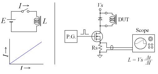
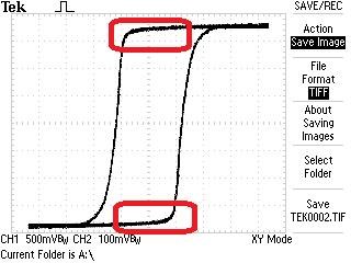
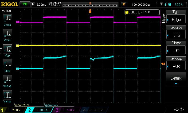
When a constant DC voltage E is applied to an inductor L like shown in right image, the current I increases proportional to the time past, I = E * t / L. If the inductance is constant independent of DC current, plotted line on the graph will be straight. However it is affected by DC current, it will plot a curved line.
Thus the inductance and its current-dependency can be easily measured by applying a voltage pulse to the inductor and displaying the current on the oscilloscope.
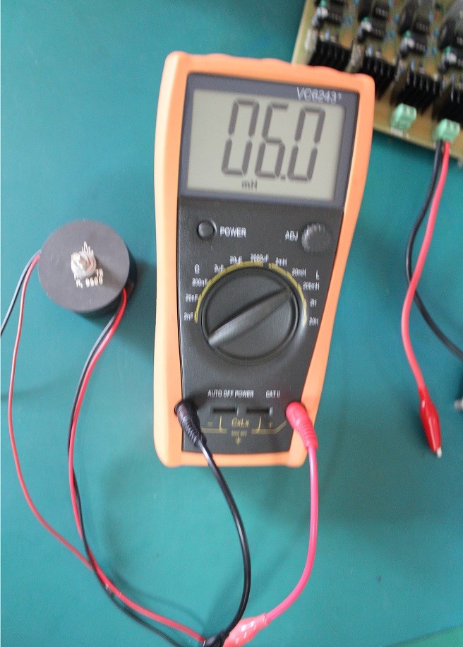
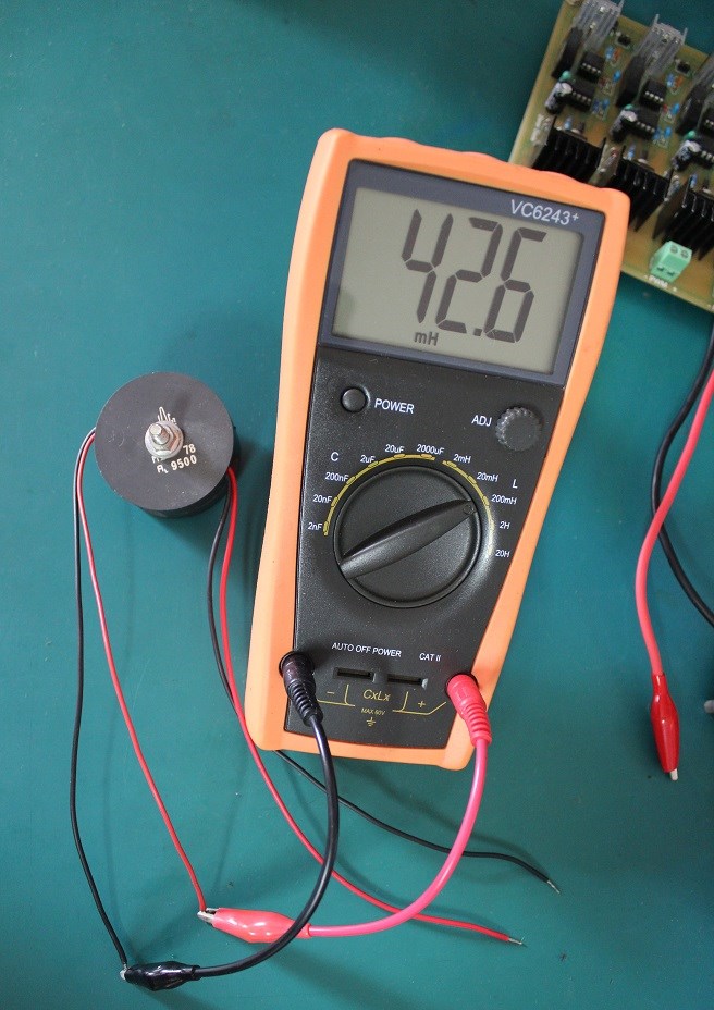
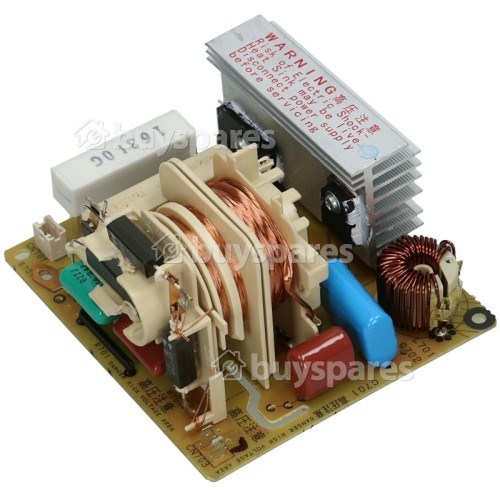
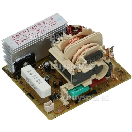
Hardware
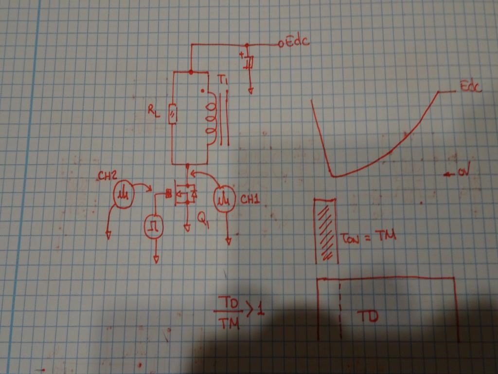
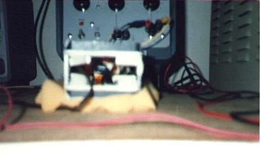
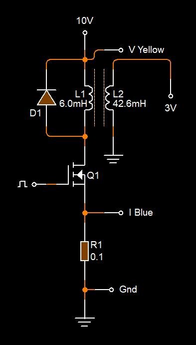
Right photo shows the build inductor checker. It applies voltage pulses to the inductor to be checked 50 times per second. The inductor current is sensed by series resistor Rs and the waveform is displayed on the scope. The inductance can be read by: L = Vs * Δt / ΔI
The pulse width is adjusted by a pot and a jumper switch for wide inductance range of inductor's, and the test voltage is supplied by an external voltage source. The test voltage is decoupled by very low ESR capacitors C1 and C2 to retain a constant voltage against high current pulses.
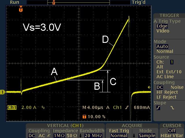
A: 21.5μH
B: Rated current = 1.7A
C: Saturated at 3A (ferrite core saturats sharply)
D: 3.2μH (after core-saturation, it works as air-core inductor, so the peak current must be kept lower than core-saturation point)
I want to be clear: I don't know if this is definitely important to our paths moving forward, it is important to know about and understand none the less.
However: There is some evidence to say that working up close to saturation, may be beneficial. Credit to YoElMiCrO, Vidura and Zanzal for this Direction of thinking.
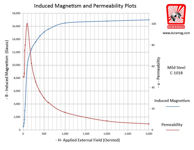
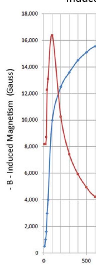
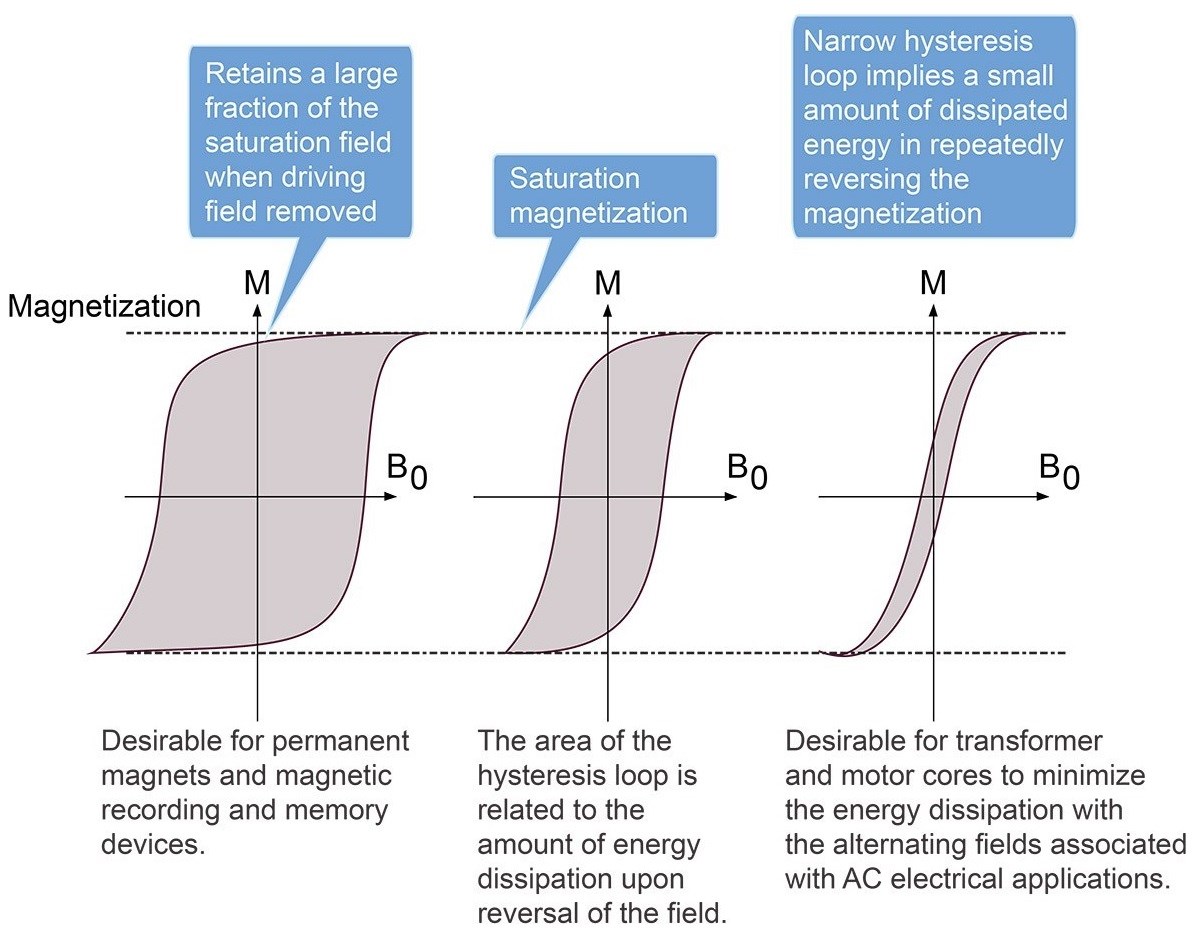
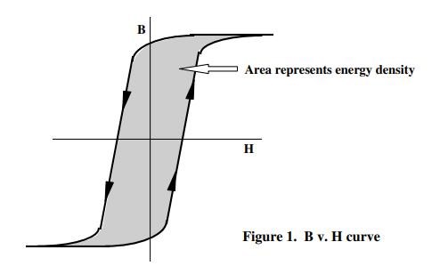
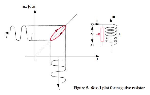
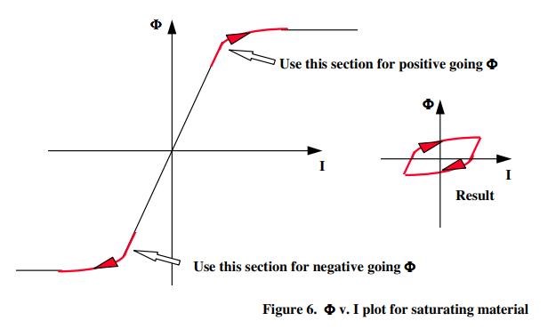
This idea is not new! Its been around and I have known about it for a long time. The Knee of the BH Curve has been shown on this forum for quite some time, this quote and image:
The Knee of the B H Curve, where we see this region of Non-Linear Inductance, is marked in Red:
I have covered Saturation before, you may remember some of my Images from prior posts:
Posted: here and here and no doubt other places.
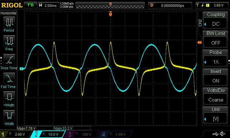
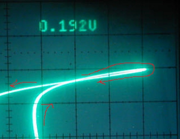
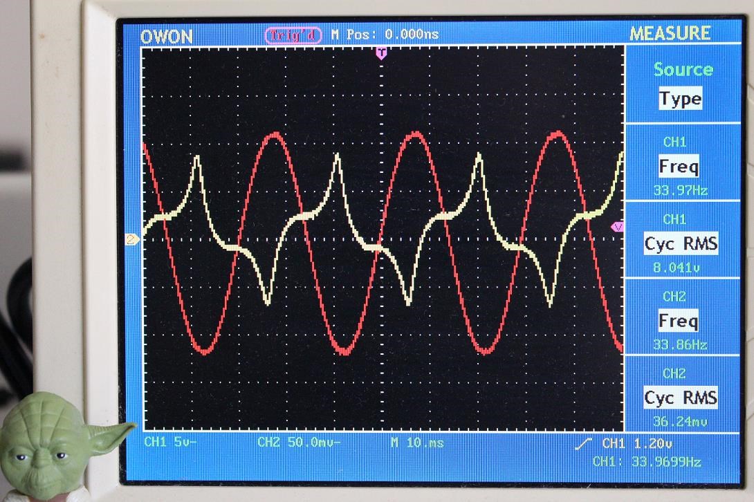
The yellow Trace, the sharp peaks indication Saturation.
I want to start this thread off with a simple experiment. I want to give others some sort of idea about the Core and referencing the Core to find out where the levels of Saturation may be found.
Experiment:
We are going to test a Core Material, looking at Frequency, Duty Cycle, Turns and Magnetising Current to start the Core going into Saturation. Remember, Ampere Turns = Turns x Current! So if we have 10 turns and 20 Amperes Peak Current, then we have 20 Ampere Turns.
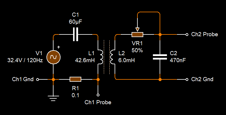
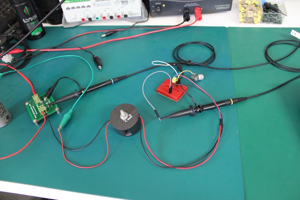
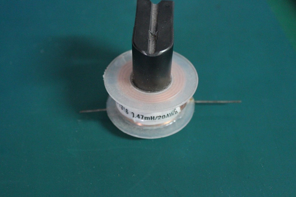
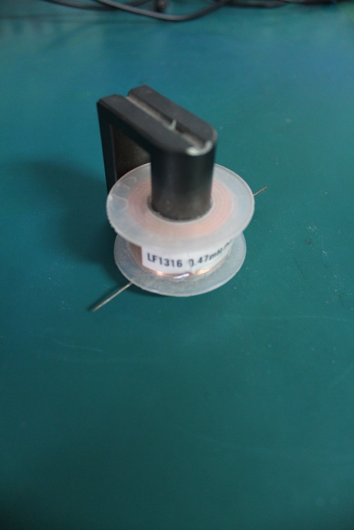
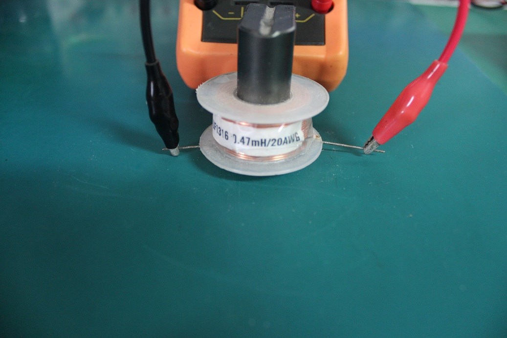
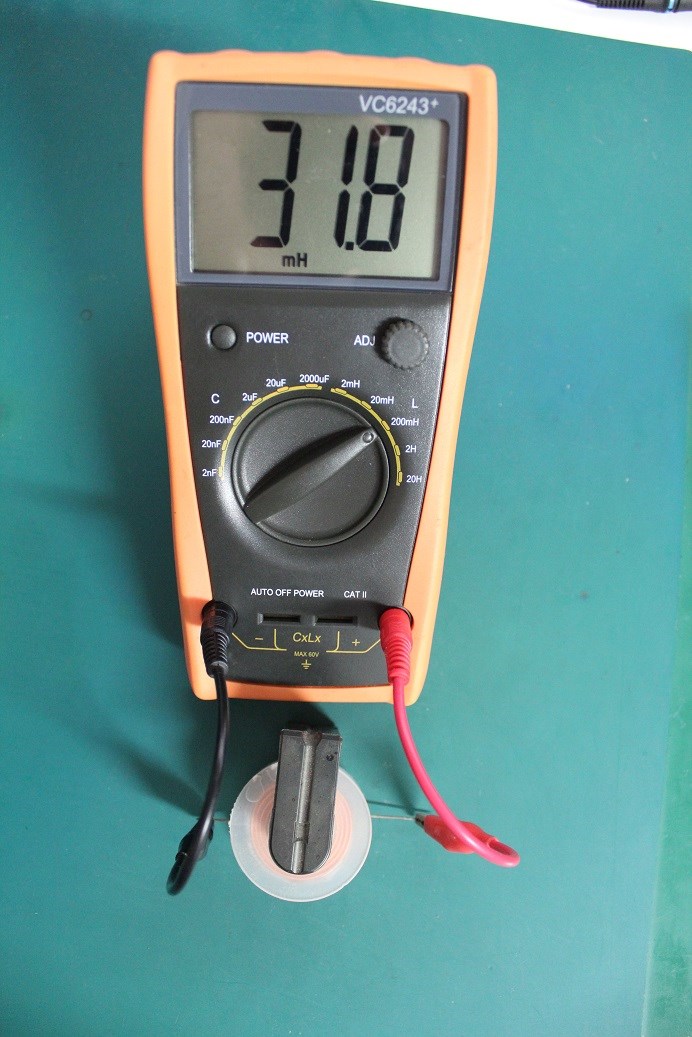
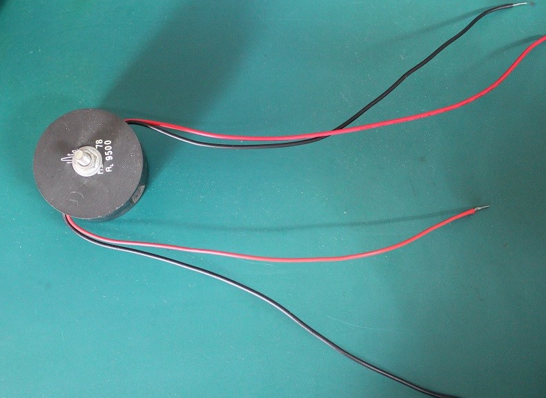
The DUT:
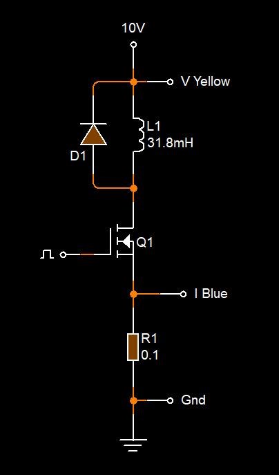
The Circuit:
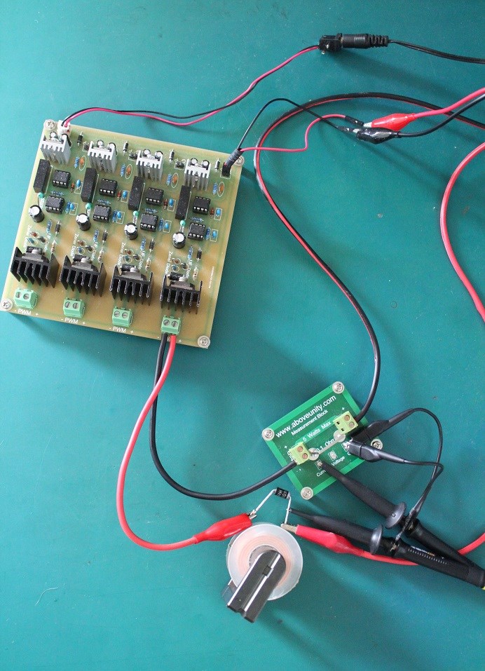
The Setup:
A very simple Circuit is used. We are looking for the above three things:
- Frequency.
- Duty Cycle.
- Current.
Results:
Very quickly I saw a problem with Constant Current on my new Power Supply. The Image showing this is here:
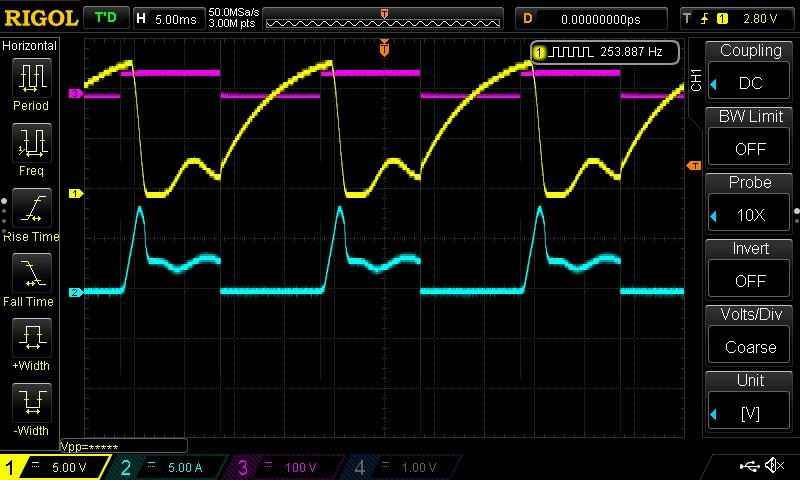
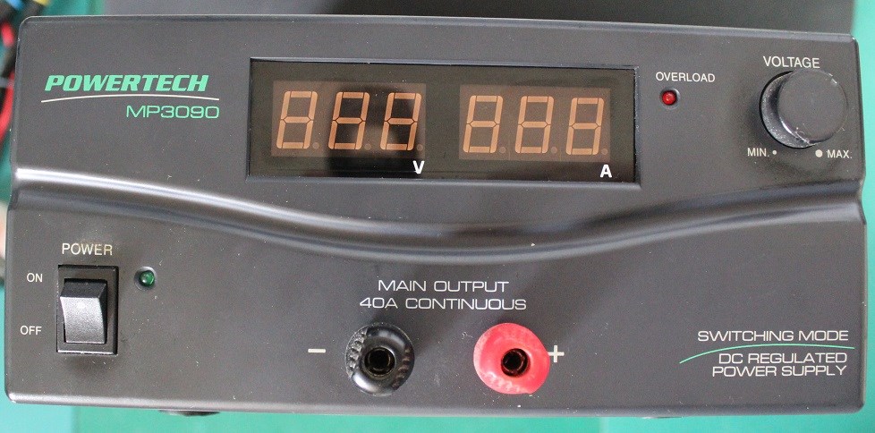
You can see, Peak Current is reached, then it falls off very fast, no more current can satisfy the Coils requirement: I = V / R, known as I2R Losses, to get the Core to saturate. I had to bring my old Power Supply out of retirement to satisfy the Constant Current Requirement:
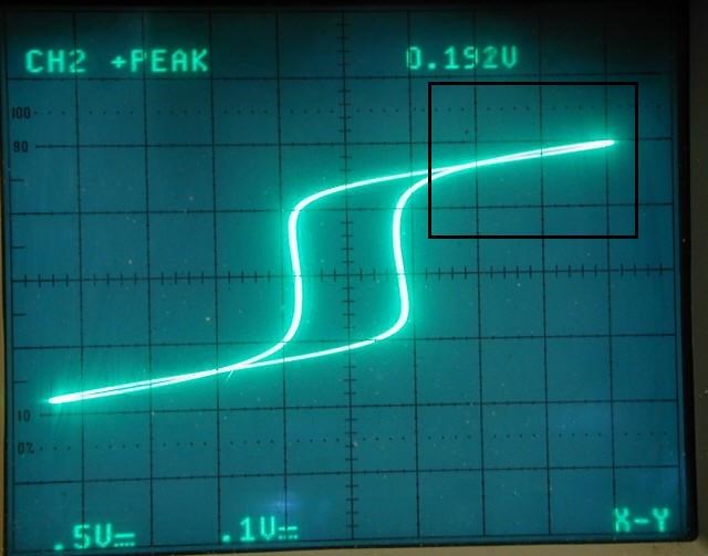
After trying again, quickly, so my equipment does not over heat, I got this image:
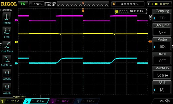
You can see, there is nearly 25 Amps there!
I am going to have to admit defeat here on this Core, I cant get it to Saturate with my Equipment! This core was not a good Choice!
Time to pick another Core, also, we are going to cheat a little bit, this is the new Test Core:
New Circuit:
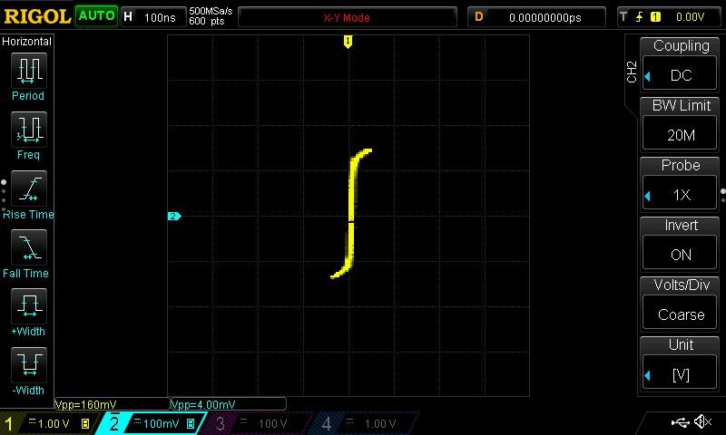
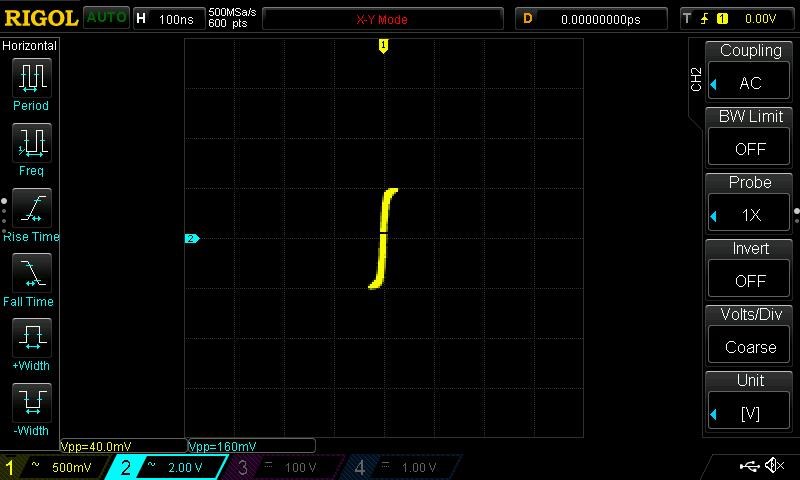
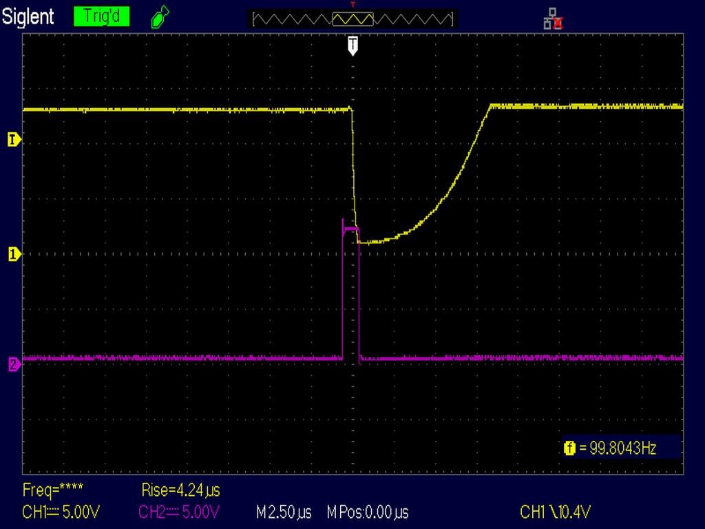
After some work, and getting the polarity right, it appears we have a Core that is starting to go into Saturation:
The slow up going wave, after about 5 microseconds, the Current starts increasing, indicating Saturation is occurring.
Remember: When a Core is Saturated, all the Inductance is lost. The Coil is just a DC Resistance, Current should increase.
Related:
Some time ago, I posted a video: Saturable Reactor
Observation:
On moving into Saturation, I see a sort of interference, the Scope starts to trigger incorrectly, and I get some extra noise, more than normal! There is some Wire / Coil type interference's.
Conclusion:
Looking at the results, we have to agree, I picked the worst possible Core I could find! This Core is out of a Panasonic Microwave oven Power Supply:
We should expect Saturation to be very high, but I did not expect this high!
In the second Core, we still saw a lot of Current used! These Ferrite Cores are heavy duty! I wanted to show that its not easy to saturate a Core, Lots of Turns is needed and also a fair bit of Current normally.
My Inputs were:
- 3 Volts @ 1.51 Ampers DC Current.
- 7.3 Volts @ 5.5 Amperes DC Pulse 50% Duty Cycle.
- Frequency: 50Hz
- Duty Cycle: 50%
I will do more experiments to see if I can get a better result.
I would like to reference a document, worth a read: A New Look at the Bearden MEG© by Smudge, May 2014 - I have to say, I don't agree with everything in this document, but its a very good start to a greater understanding!
I am sorry, I cant be sure 100% on this area, I am speculating, but some of this does make some sense!
Also, the old Biological Thermometer, using your finger as a thermometer is not a good idea, please be careful:
Best wishes, stay safe and well!
Chris