

The Spark Gap was a common component to many devices back in the day, we still have some applications for it now.
The Great Nikola Tesla perhaps made the Spark Gap famous in his Tesla Coil:
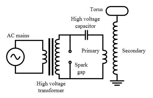
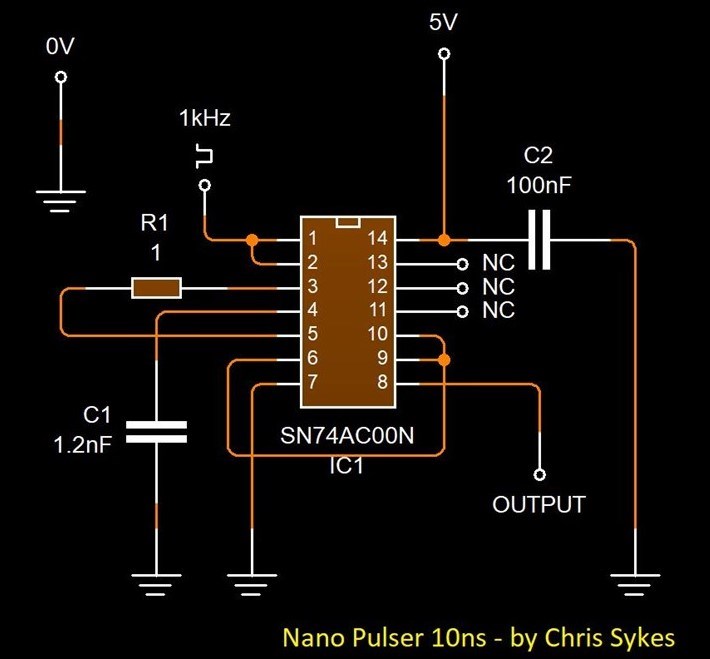
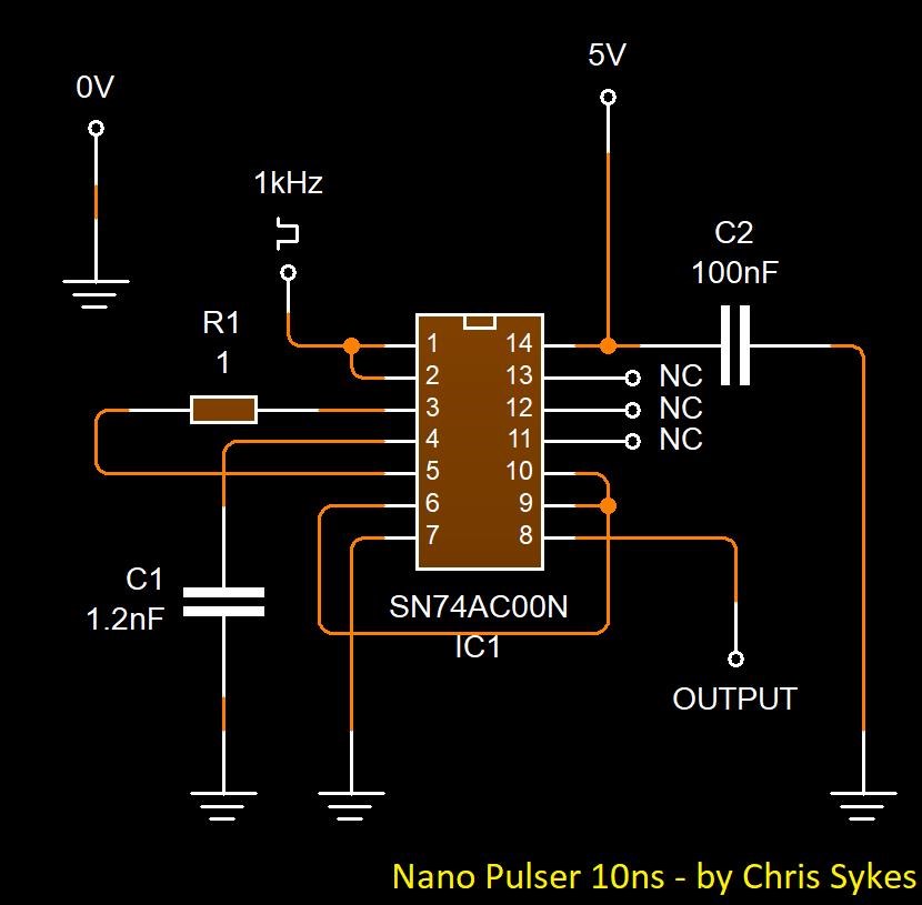
We have seen this many times, many times in different application, circuits replacing the functions of the Spark Gap, some call it a Nano Pulser, a Nano Generator, Generator of Nano Second Impulse (GNSI), and many other names exist for such a technique!
One I am fond of, due to the openness of it, was Dally! Real name: Edward Lee
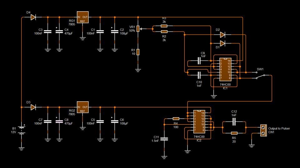
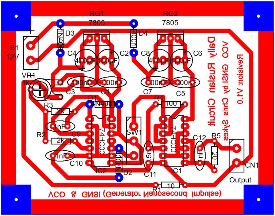
His circuit was very well shown:
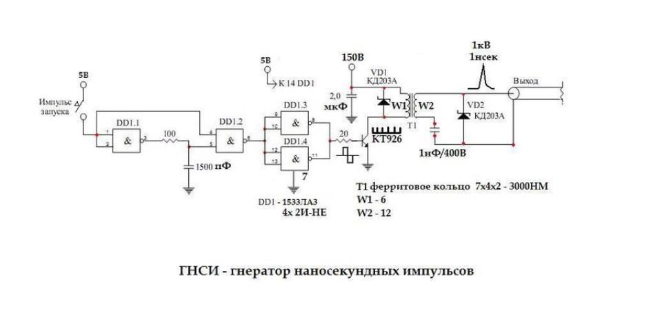
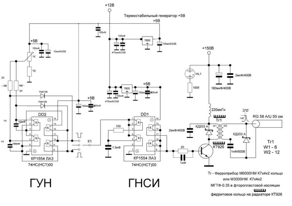
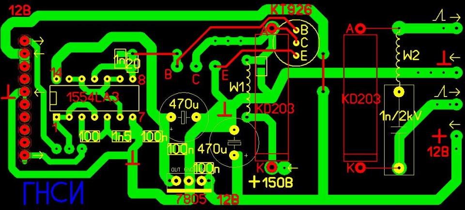
The function, to inject a very short duration pulse, at high Voltage, into a Coil that is in close proximity to Bucking Coils! The list of people that have used this is endless: Tariel Kapanadze, Ruslan, Akula, all used this technique many times
It is my opinion, that this is a method of Electron Paramagnetic Resonance, some have called this Ferro Magnetic Resonance, a few different names have been used!
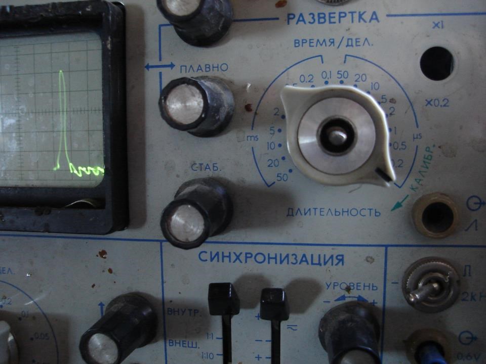
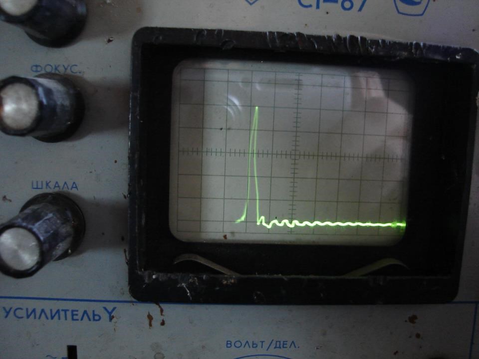
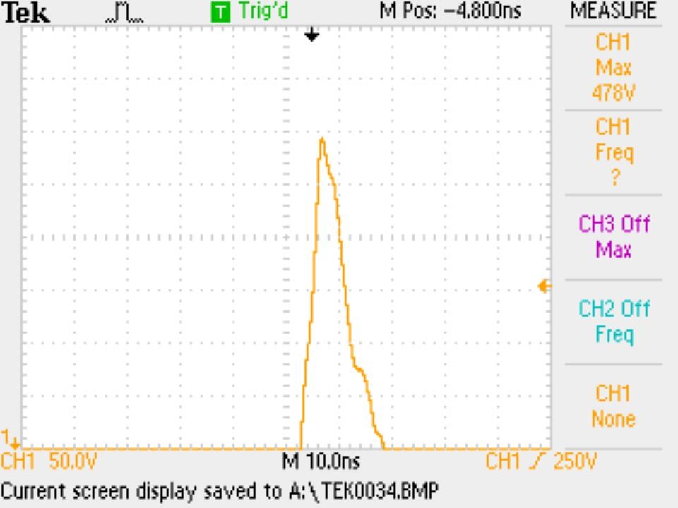
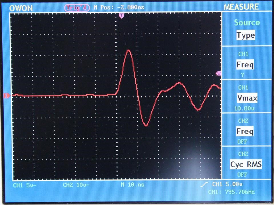
I have build a few Circuits, copied from Dally, but my Nano Pulser circuits were too slow, only around 500 Nano Seconds.
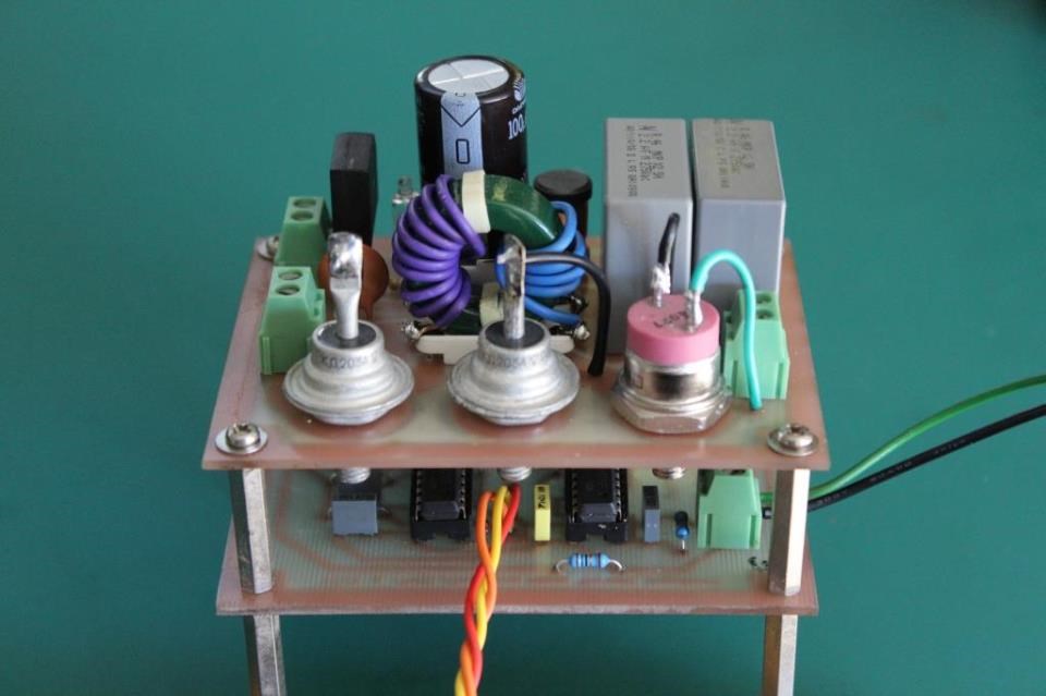
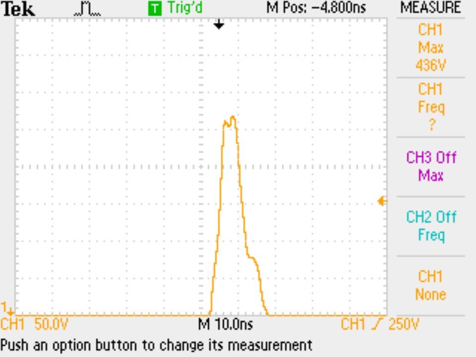
It is critical to be around 10 Nano Seconds or less!
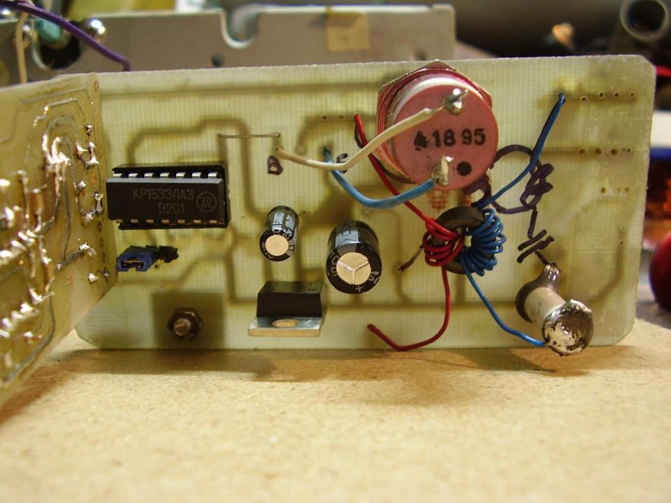
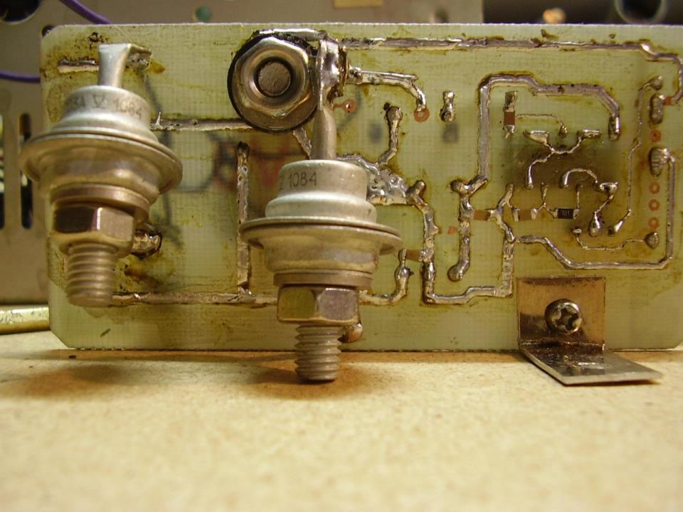
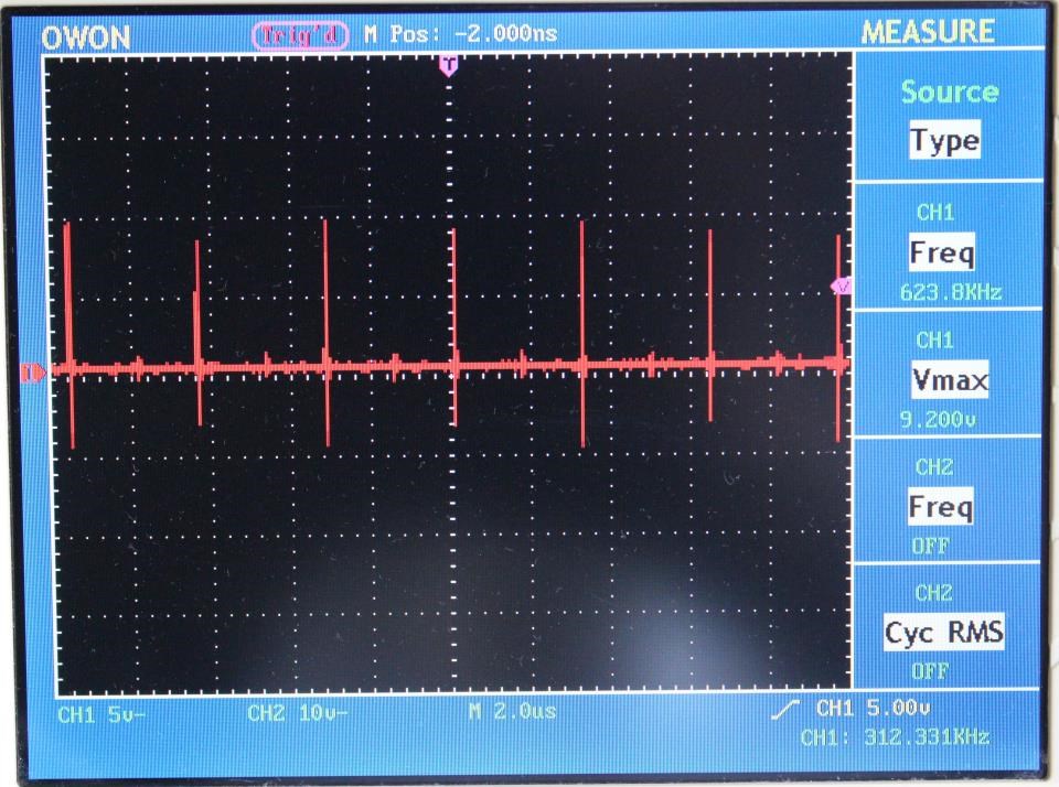
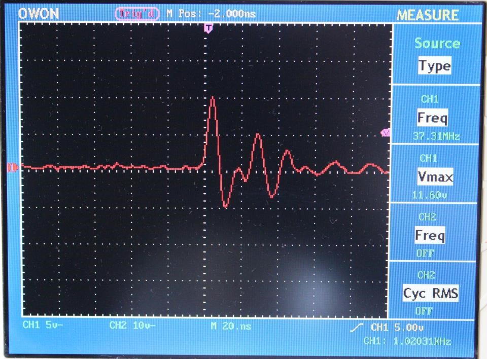
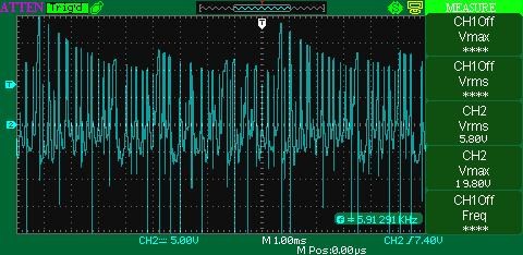
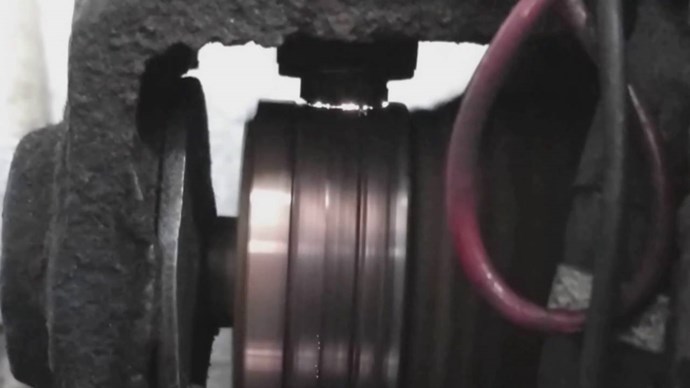
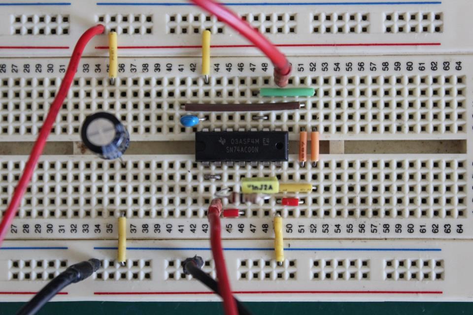
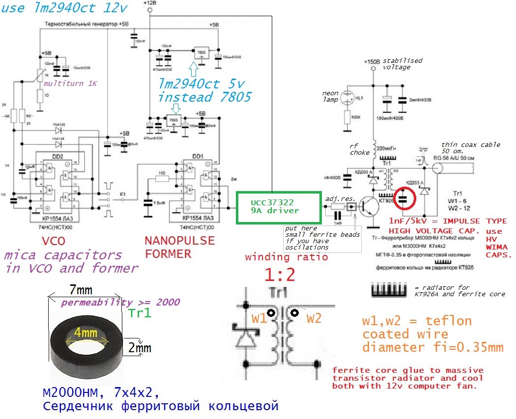
The above Images were given to me by a friend. This friend knows Ruslan Kulabuhov, has worked with him from time to time. Built Circuits for him.
Chris


 It is easy to accept someone else's doctrine, but clearing a path for your own doctrine is Real Science, let no Rules Bind You!


---open-tesla-research.jpg?width=20&crop=0,0,20,20)


