Steps to Avoid Failure

  • Topic Is Sticky
  • 1.7K Views
  • Last Post 11 August 2020
Chris posted this 02 April 2017

This section is a work in progress - I am still learning and as we continue to experiment, we continue to learn.


Goal:

We want to have Electromagnetic Induction occurring more than once in a System, An A-Symmetrical System


What to look for:

Several times I have seen the same problem, some people even report: "I am only getting Transformer Efficiency's"!

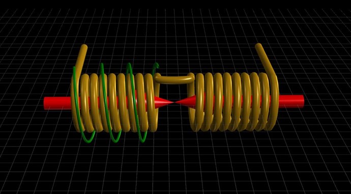
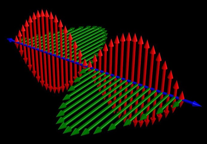
Most of the time, the reason for this is simply, that: The Magnetic Fields, the Currents, are not in Opposition to each other!

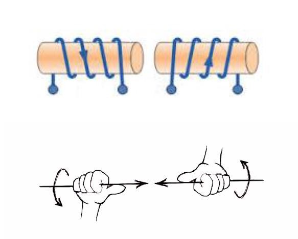
This is irrespective of the Winding Geometry's or Configurations! Fields must oppose no matter what!

A Transformer is based on Electromagnetic Induction, which is the Time Rate of Change of the Magnetic Field in the Proximity of the Conductor:

E.M.F = - N dΦB / dt

Where:

E.M.F is the potential difference in charge between two terminals of the "Generating" Coil.

Negative Sign (-) is Lenz's Law, an equal opposite Magnetic Force from the "Generating" Coil reflected back on the Source Magnetic Field.

Number of Turns (N) is the Number of Turns on the "Generating" Coil.

B is the Variance of the Magnetic Field B. Min to Max Field.

dt is the Change in Time (t).

Transformers, Transform, Voltage and Current, there is Electromagnetic Induction occurring only Once in this Symmetrical System! We can either Step up or down these units, one being the inverse to the other. Meaning, to step up Voltage, Current is stepped down and vice versa.

Transformers aside, in our devices, depending on your configuration, the Input Current becomes the Output Current, less losses, all Systems have Losses, and there is not sufficient Electromagnetic Induction to make a difference to the System! Thus the statement:"I am only getting Transformer Efficiency's"


Sometimes Magnetic Fields don't Oppose?

In our configurations, it is the case that sometimes the Currents don't oppose. This is a very odd problem! 

It is the case that the Input Current is greater than the amount of Electromagnetic Induction between the Partnered Output Coils! This is quite common! Personally I have not seen this very often, and I will explain why I believe this is so.

As stated above, the Magnetic Field and the Change of it in the Proximity of a Conductor (Coil), is the requirement for Electromagnetic Induction. Turns (N) also being part of the equation. Also, the Magnetic Field B is deemed a quantity that is dependant on the Turns (N) the Current (I) and Length (l (small L)), the equation takes this format:

B = µ0 N I / L

 Where:

B is the Magnetic Field in Gauss

µ0 is the Permeability

N is the Number of Turns

I is the Current

L is the Length of the Coil

 It is interesting to note the old term "Ampere Turns" (AT) is AT = NI

 When the Magnetic Field (B) is not sufficient to Induce a E.M.F in the Opposing Coil, then the Current we put into the Circuit will become the dominant Current.

There will not be enough Electromagnetic Induction occurring in the System to Invoke Opposing Magnetic Fields!

The cause of this can be twofold:

  • Not enough Current flowing through the Coils!
  • Not enough Magnetic Field!

 Because this is a Chicken of the Egg scenario, we have to look at solving this problem from a few angles.

  • Increase the Current flowing.
  • Increase the Turns on the Coils and keep the Current the same.

Because the Turns are a quantity in the above equation, and by keeping the Current the same, we get more Magnetic Field as a result! This also increases the Electromagnetic Induction occurring.


Cores

 Some Cores are Slugs! I have tried a few cores and they just don't want to play nice! So trying another core may help sometimes!


Reflectance:

I am not sure 100% here, so this section could change at any time also.

If an Antenna is not matched for a particular Radio, the Signal will reflect and the Radio will not receive as much signal as it should! The radio can be damaged as a result!


I believe this is part of the reason we often look at the 1/4 Turns ratio!


How to Check:

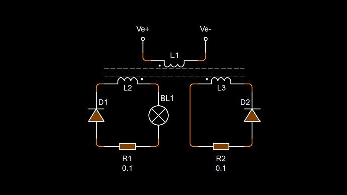
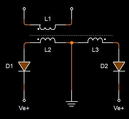
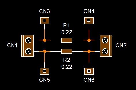
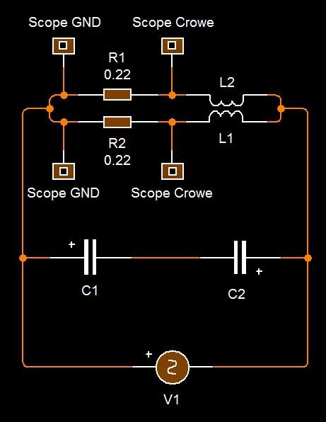
I monitor my Currents with Two Current Sensing Resistors:
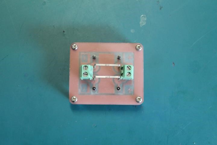
 

Summary:

So, I guess, first step is to ensure you have Currents flowing in Opposite directions, Magnetic Fields must Oppose! Thus the importance of the MrPreva Experiment! There is a little fiddling, so stick with it! Don't give up!

Please keep checking this post to check for changes.

Order By: Standard | Newest | Votes
Chris posted this 11 August 2020

My Friends,

I am concerned that many are suffering from Confusion?


We all suffer from Confusion, but we must control it! It is an emotion, of sorts, that we must take control of and handle with extreme care!

If I may give some advice that has helped me?


Treat Each Coil as an individual Coil:

Each Coil has a job of its own to do, this means you must tread each Coil as a singular, individual Coil!


I have posted this circuit, or very close variants of this circuit:


You will notice:

  1. L2 Opposes L1.
  2. L3 Opposes L2.
  3. L3 Assists L1.


You will also notice, this Circuit is Asymmetrical! Symmetry is broken, a System that has a Coil ( L3 ), that is not in opposition to the Primary Coil! We have a Standing Wave.

We do have Symmetry, of sorts from the Primary ( L1 ) to the Secondary ( L2 ), but this is only Magnetic Field Symmetry for the period of On-Time of the Primary ( L1 ). This On-Time is very short, 10% Duty Cycle or so.

For the entire Cycle, there is 90% Asymmetry!

Total Work: P = IE, Joules Law, must be greater if the Force, M.M.F is greater than the Input M.M.F. Remember M.M.F is equal to NI, N = Turns and I is Current.

Ref: electronics-tutorials.ws


Ref: www.electronics-tutorials.ws


The Standing Wave Requirement.

Many pages on this forum cover this basic fundamental requirement! The two Output Coils must oppose each other:


Where:

  • Red Arrows are the Magnetic Field Vectors B, B + B` = 0.
  • The Green Arrows are the Magnitude the the Current. Current i = 2 x I.


The Red Arrows, show the requirement of Magnetic Field Opposition of the Partnered Output Coils, Magnetic Resonance, where each Current is 180 degrees out of phase. This part is super important!

In the series, Chris's Non-Inductive Coil Experiment, we learnt a lot about Coils, Voltage and Current! I recommend great study on this topic! There is a lot of gems in there!

We must:

  1. Magnify Voltage - Step Up using Turns.
  2. Magnify Current - Using Magnetic Field Opposition. A Standing Wave or magnetic Resonance.


Please understand, all we are building, is a Solid State Electromagnetic "Generator"! Nothing more! We require Three Moving Magnetic Fields, all in a sort of Resonance.

Don Smith was 100% Right! Study his Coils up to the Diodes:


In the following video, count how many times Ruslan says the word Resonance:


The Circuit:

Best wishes, stay safe and well My Friends,

   Chris

Chris posted this 02 April 2017

Hi Cd_Sharp - That will be fine.

The Circuit:

The basic MrPreva Sensing Circuit would be something like this:

Please remember, the Ceramic Resistors you have are Wire Wound Resistors, these will not be any good for High Frequency DC Pulses, they will introduce a lot of Noise via Parasitic Inductance, which is actually the Exact effect we are Capitalising on! For an example of this:


What is shown in the above video, is Electromagnetic Induction, the Time Rate of Change of the Magnetic Field in the Proximity of a Conductor, this is exactly the same as how Electrical Energy is "Generated" in an Electrical Generator!

I hope this helps!

All the best

   Chris

  • Liked by
  • Augenblick
  • ISLab
Chris posted this 02 April 2017

Hi Cd_Sharp - Yes I built them for myself. They very simple, one could just use Terminal Blocks instead and two 0.1 Ohm Resistors.

I am glad that this post helps!

All the best

   Chris

  • Liked by
  • Augenblick
We're Light Years Ahead!
Members Online:
What is a Scalar:

In physics, scalars are physical quantities that are unaffected by changes to a vector space basis. Scalars are often accompanied by units of measurement, as in "10 cm". Examples of scalar quantities are mass, distance, charge, volume, time, speed, and the magnitude of physical vectors in general.

You need to forget the Non-Sense that some spout with out knowing the actual Definition of the word Scalar! Some people talk absolute Bull Sh*t!

The pressure P in the formula P = pgh, pgh is a scalar that tells you the amount of this squashing force per unit area in a fluid.

A Scalar, having both direction and magnitude, can be anything! The Magnetic Field, a Charge moving, yet some Numb Nuts think it means Magic Science!

Message from God:

Hello my children. This is Yahweh, the one true Lord. You have found creation's secret. Now share it peacefully with the world.

Ref: Message from God written inside the Human Genome

God be in my head, and in my thinking.

God be in my eyes, and in my looking.

God be in my mouth, and in my speaking.

Oh, God be in my heart, and in my understanding.

Your Support:

More than anything else, your contributions to this forum are most important! We are trying to actively get all visitors involved, but we do only have a few main contributors, which are very much appreciated! If you would like to see more pages with more detailed experiments and answers, perhaps a contribution of another type maybe possible:

PayPal De-Platformed me!

They REFUSE to tell me why!

We now use Wise!

Donate
Use E-Mail: Chris at aboveunity.com

The content I am sharing is not only unique, but is changing the world as we know it! Please Support Us!

Thank You So Much!

Weeks High Earners:
The great Nikola Tesla:

Ere many generations pass, our machinery will be driven by a power obtainable at any point of the universe. This idea is not novel. Men have been led to it long ago by instinct or reason. It has been expressed in many ways, and in many places, in the history of old and new. We find it in the delightful myth of Antheus, who drives power from the earth; we find it among the subtle speculations of one of your splendid mathematicians, and in many hints and statements of thinkers of the present time. Throughout space there is energy. Is this energy static or kinetic? If static, our hopes are in vain; if kinetic - and this we know it is for certain - then it is a mere question of time when men will succeed in attaching their machinery to the very wheelwork of nature.

Experiments With Alternate Currents Of High Potential And High Frequency (February 1892).

Close