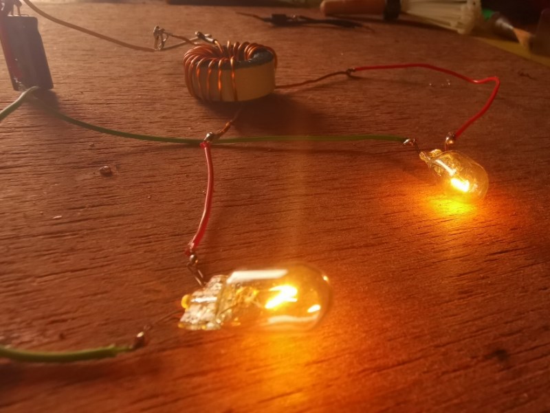
The MrPreva Experiment

  • Topic Is Sticky
  • 18K Views
  • Last Post 30 November 2022
admin posted this 23 March 2017

I think this is perhaps one of the most important experiments anyone could do! A huge amount of information can be learned by running this very simple experiment!

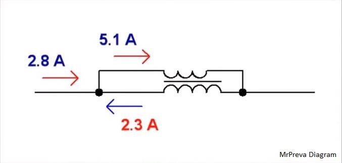
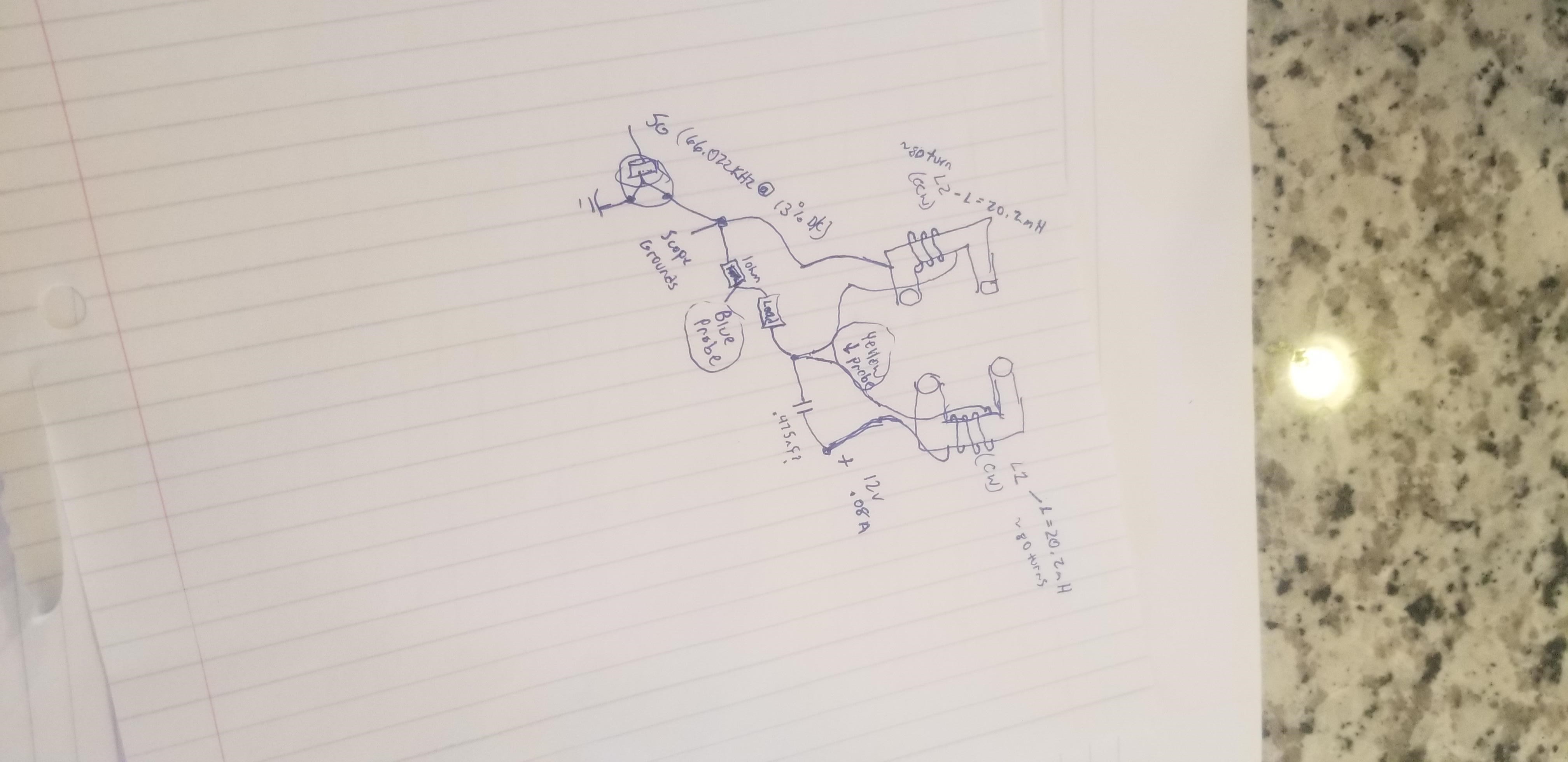
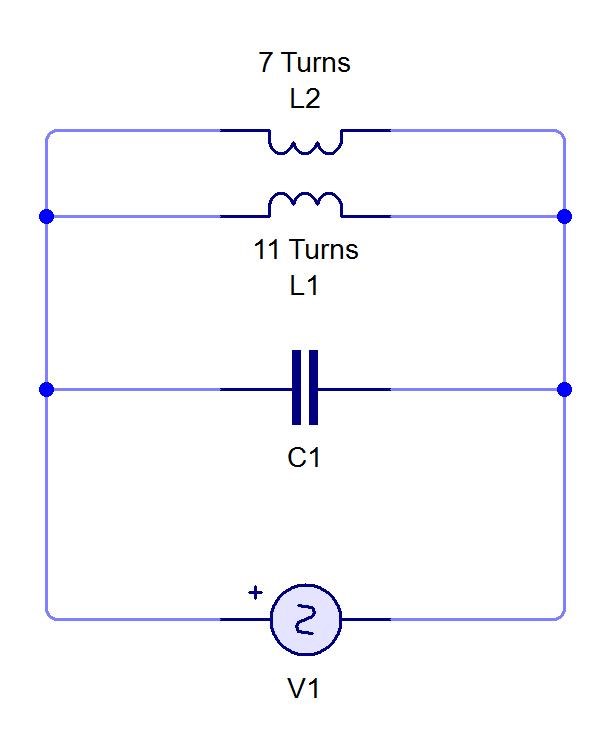
The MrPreva Experiment Circuit

Please Note: The Current's (I), add, Floyd Sweet talked about this specifically:

In the specific case of positive charges moving to the right and negative charges to the left, the effect of both actions is positive charge moving to the right.

Current to the right is: I = da+ / dt + da- / dt.


Negative electrons flowing to the left contribute to the current flowing to the right.


The total Current, is the Sum of the both Currents!


We see, 2.8 Amps (da+ / dt) + 2.3 Amps (da/ dt) = the shown: 5.1 Amps as Floyd Sweet told us.

We see a Negative Power Factor, where the Voltage (V) Current (I) are out of phase by a Degree, which results in a Negative Power Factor!

cos(theta)

Where theta is the Phase angle in Degrees. EG:

cos(180) =  -1


You will see there are some problems with the MrPreva Circuit, and it is explained, because, the Current (da- ) has become a Generator, or a Battery, which is the only time  Kirchhoff's Current Law does not hold in an applied situation. 

Order By: Standard | Newest | Votes
Chris posted this 30 November 2022

Hello Vinyasi,

Initially I thought your post was span, a link to... and it was not something we believe in...

I thought I would go and read further, its an ok document, written by someone, or multiple someone's with a very average Engineering Knowledge!

The writers have taken ideas from others and made some very poor interpretations and assumptions about a field that they very obviously know little about, atleast they admit it:

Attempts at producing free energy don’t have to be fake. There’s no guarantee, either way, for them to be fake or real, since there’s a general lack of knowledge on this complicated subject...


A wise poster then posts at the bottom:

“@Leaderboard, I forgot to mention...
Electrical engineering has always allowed for free energy circuits by renaming them: unstable. In other words, "energy IN does not equal energy OUT" defines an unstable circuit in which you can't predict the output based on the input, alone. This is in addition to an allowance for a shift in time due to the frequency component of the formulae for electrical reactance supersedes Conservation of Energy.[59] Thus, Conservation of Energy is not a law so much as it is a yardstick by which circuit topologies are measured to determine a circuit's type. If a circuit's output is unpridictable (based on its input, alone), then it is unstable since its output was not conserved within the boundaries imposed by its input. Type-casting is not disallowance; it is merely prejudice.


You know, the title: Free Energy does not Exist, but Free Voltage does Exist! shows a total ignorance of the other half of Electrical Engineering that is not Symmetrical, which only a small part of the article shows exists!

Best Wishes,

   Chris

  • Liked by
  • ansen
  • Augenblick
Vinyasi posted this 30 November 2022


Anomalous Kirchhoff Behavior

Splitting a transmission line into two branches should divide up the current, according to Kirchhoff's Laws, and maintain the same direction (ie, polarity) of current for both branches, yes?

This law, also called Kirchhoff's first law, or Kirchhoff's junction rule, states that, for any node (junction) in an electrical circuit, the sum of currents flowing into that node is equal to the sum of currents flowing out of that node; or equivalently: The algebraic sum of currents in a network of conductors meeting at a point is zero.

      But what if conventional expectations are not always right? What if, sometimes, anomalous events can occur?

Chris posted this 16 October 2021

Hi Scalarpotential,

Please feel free to create your own thread, the replication of the Mr Preve Experiment, and show us your progress. We would love to see it!

Best Wishes,

   Chris

  • Liked by
  • Shadow_
Chris posted this 14 October 2021

Hi Thay,

The V x I in The Mr Preva Circuit, should be invariant of the Input Circuit Supply because at Resonance the V x I circulates in the Tank Circuit itself.

Finding the Resonant Frequency, and then turning up the Input Voltage and then fine tuning the Circuit Frequency is ideal, but this Experiment is not really about pushing boundaries of Input Power, its more so about observing what Magnetic Fields do under a defined circumstance, the Pumping of Electrons in a Circuit, or Amplifying Current.

Best Wishes,

   Chris

  • Liked by
  • strape
  • Augenblick
thaelin posted this 13 October 2021

Hi all:

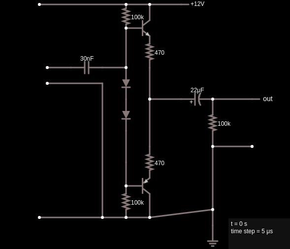
    I have not done this as I have not had a way to drive the circuit with ample V/I till now. I ran into this push/pull circuit that I feel will allow one to use their variable PS as the input and drive it with a simple FG. Notice this is a complimentary pair like is used in home stereos. The pairs that I have are 60v 125w max. Much more than needed for the Preva test. Hopeful the pic will imbed right. Did a screencap of falstad layout. Got this off the net and is not my design. 


Was afraid of using my 100w audio amp as it is wanting to see 8 ohms only on the output. Think this will allow a lot of lee way in values. Will be doing this test as soon as the amp is ready.

thay

Dennis posted this 13 September 2021

Hey guys,

i´ve been very busy the last few months, so I couldn´t experiment anymore. I hope, the next few weeks will be a little unstressed, so I can go on and show some progress. Besides, i´ve forgotten my login data for my old account and the "forgot my password" function didn´t work

Kind regards

Dennis (MalReynolds)

Chris posted this 20 August 2021

Hi Brian,

Fantastic work! Thank You for sharing!

The Mr Preva Experiment is an excellent step forward for sure! We have worked on the Akula Machines, particularly the Lantern, for a little while. I have some success back in the day, and tried to share some of it. Not many paid any attention.

The video here:


If you turn on Closed Captioning and translate, he tells you exactly how to do it!

Remember, the Mosfet is just a switch, thats all, what can be adjusted in the switch, basically only about 4 parameters:

  • Frequency
  • Duty Cycle
  • Rise Time
  • Decay Time


Akula tells you how to do it, forget about building Circuits, use a Function Generator, and focus on the above parameters and what Akula told us. He was right!

Yes Primary and Seciondary Buck, Standard Electromagnetic Induction. So make sure this polarity is correct, it needs to be.

Some here have working machines using what Akula told us! This does work!

Initially I belived this has something to do with Electron Paramagnetic Resonance, and still do, but its really not complicated at all, so dont let it get complicated.

Dont waste time on Circuits untill you see the effects, some Circuits on this forum may help once you get the desired effects occuring.

Best Wishes,

  Chris

Brian posted this 20 August 2021

Hi Team

I came across this site during research on Akula and his Lantern / Flashlight builds.

This site is by far ahead of the field in the quality of information available. I would like to congratulate Chis and all contributors on this.

I arrived looking to understand how Akula was able to extract excess energy from his circuits and i believe the lesson from Mr Preva has turned the light on (so to speak ).

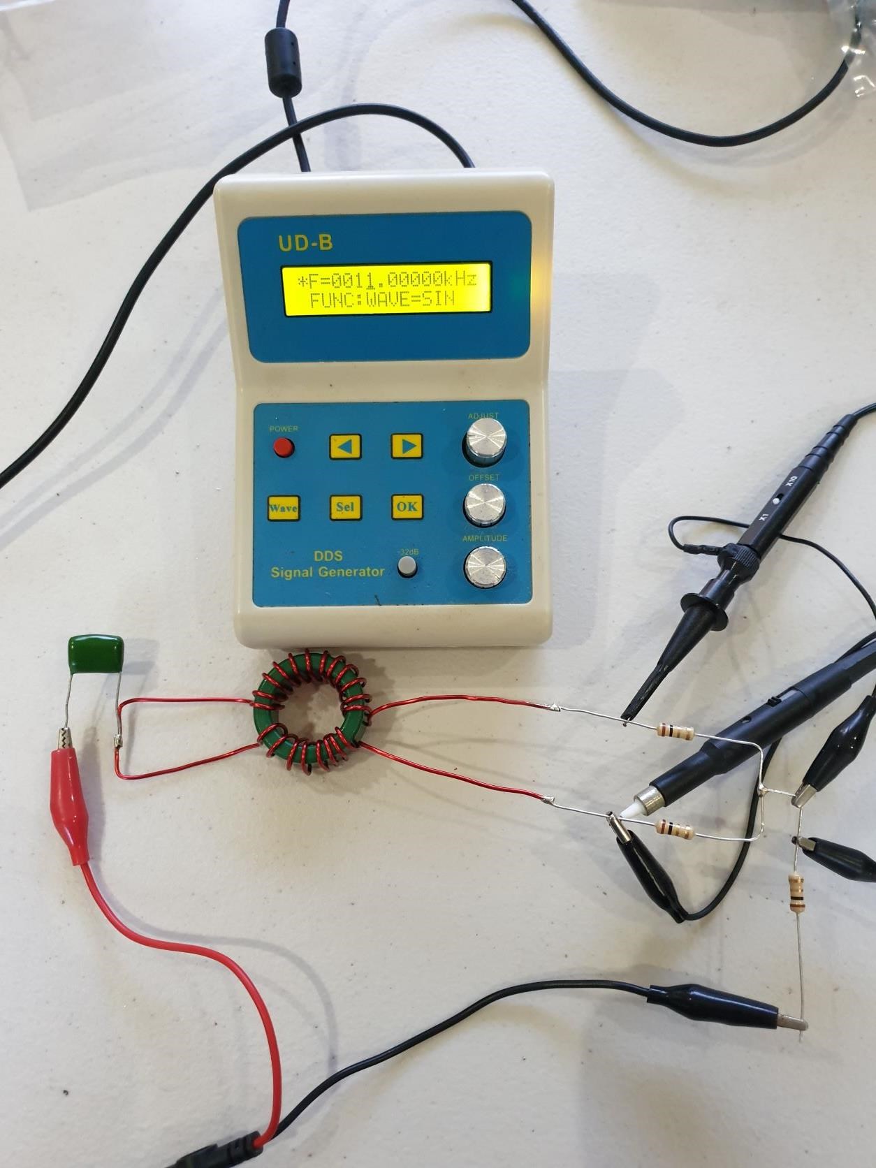
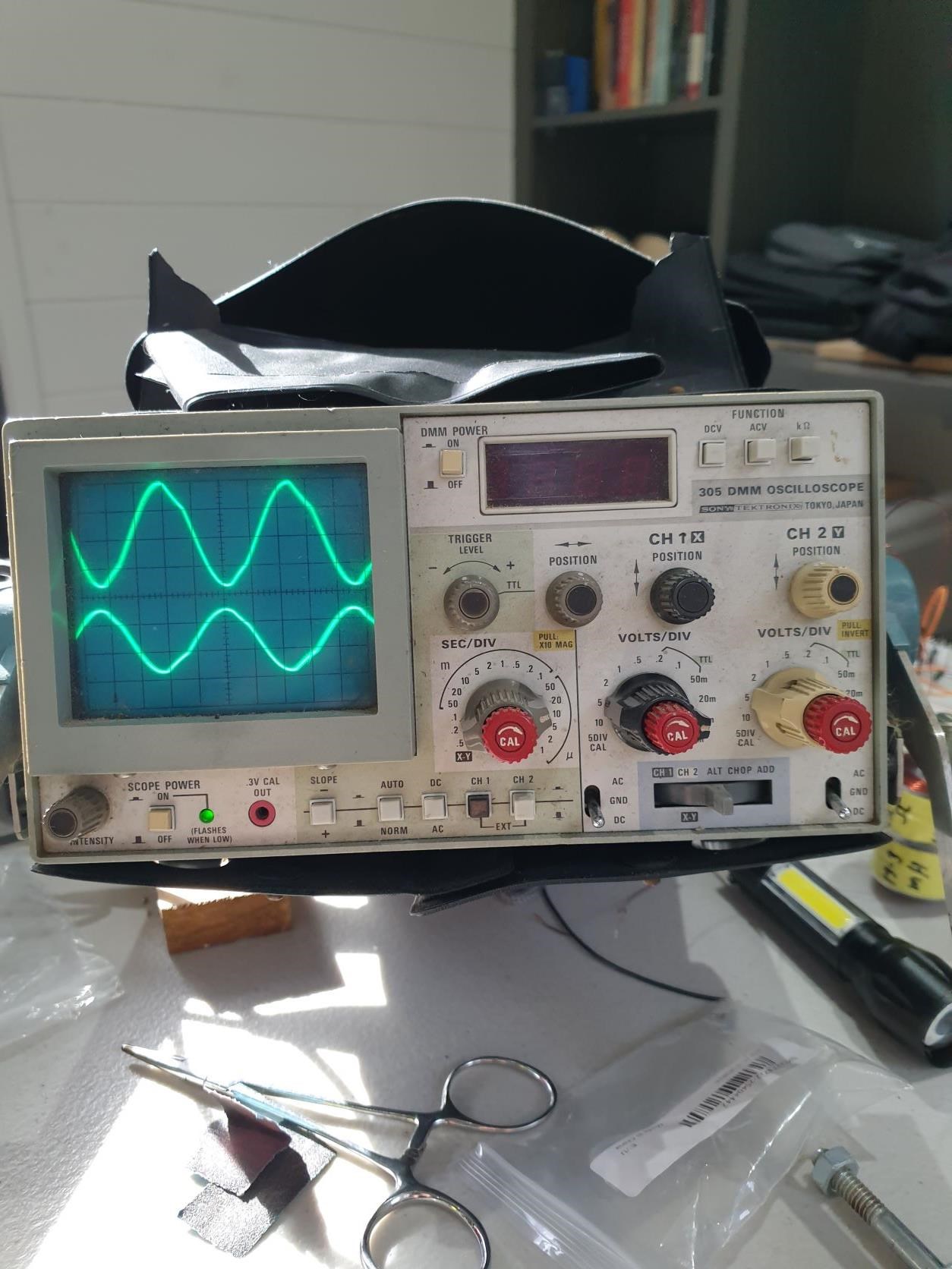
So my first step in this understanding was to raid the parts box, pull out a old scope (yes it is vintage) and knock something up. And here it is.

The calculated Resonant is around 11Khz and the Sig Gen has a 10V p-p output

All worked very neatly with the teachings of Mr Preva

The probes are x10 (I had to repair the x1/x10 set which I have now) The 180 phase difference is as projected.

I had expected the transformers in Akula's various builds to be of a concealed unbalanced nature, but this has demonstrated the possibilities from a simple CW/CCW coil.

Thankyou for the lesson

Chris posted this 20 December 2020

Hi Dennis,

I think using what you have got, has worked fine! I think keeping this simple and cheap, only upgrading if you have to, is the best path forward! I think you have achieved a very important milestone! What you have seen, it is very important to understand it!

If I may, read this thread, list the important things you have seen, make a point of knowing what it is youre looking at, learn as much as you can, this is just as important as doing the experiment!

Best Wishes,

   Chris

MalReynolds posted this 19 December 2020

Hey guys,

thanks for the quick answers. 

I will go back and start to re-read a few things. And maybe it´s time for a small power amplifier to overcome the disadvantages of the JDS6600. 

I´ll keep you informed.

Dennis


drago posted this 19 December 2020

Hey,

I know, I´ve missed something. But I don´t know what...

Dennis

Hello mate.
It is good that you have started experimenting.
@Chris has made a very good post,Lots and Lots of information / Food for thought.
however.... ,
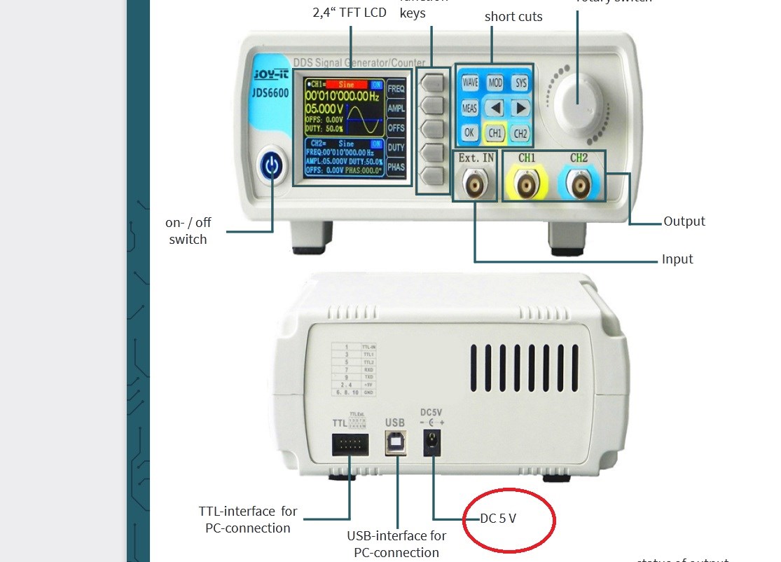
The problem is the JDS6600, that is also MY Signal generator, and it can output 20 Vpp and 0.02 A (Aprox )
As you can see in the Second picture..the INPUT is 5 V , and you hit the circuit with 20 V.
The DDS Signal Generator makes a STEP UP,and it is trading Current for Voltage.
As the MR PREVA Experiment is not MAGIC,we DO need to hit the circuit with some CURENT else we will not notice the effect.
Next time I will not buy anything if it does not a very specific Instructions and Device details.
I wish you good luck and keep experimenting !!
@drago


Chris posted this 18 December 2020

Hey Dennis,

Awesome Work! This is really nice to see so many excellent experiments! Tons can be learned here!

In your image:

oscilloscope_lamps


The Sharp Peaks in the top trace, in the above image, shows Core Saturation, thus the Phase Angle has been lost, Current and Voltage are in Phase. In the first Image, you show a large Phase Angle, approximately 100 Degrees.

NOTE: Research what occurs when we surpass 90 Degrees. You will not believe what you have achieved!

It is important to see, in this Experiment, we are Pumping Current, the Magnetic Fields, and the Opposition of Magnetic Field, in Resonance, is what pumps Current, First a Voltage is "Generated", the Voltage allows for the Flow of Current, the Current is supported by the Opposition, the Pressure, of Magnetic Fields.

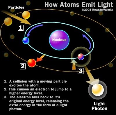
Remember Particle Physics, the Electron Orbital can be Changed by adding Energy to, or taking Energy away from, the Electron, thus changing its orbital.
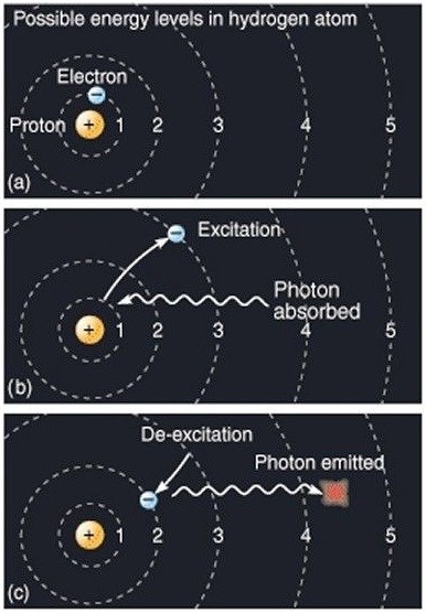
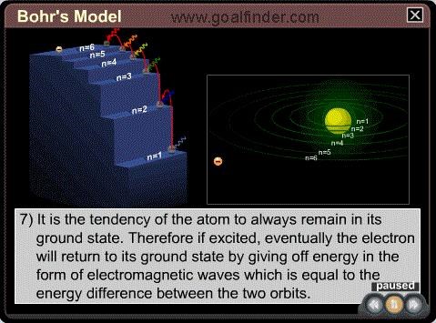
 

Again, What Is Current? 6.24 x 10¹⁸ Electrons past Terminal T1 in one Second = One Ampere.

So the near Doubling of Current in this Experiment, in One Cycle, is simply the Pumping of Electrons on the Outer Orbitals. The Coils, plural, are doing Work! We have an Electromagnetic Charge Pump!

Floyd Sweet said:

The current and potential windings require relatively little power, and are applied in such a manner that rate of flow of moving charges may be accelerated beyond 1 Ampere = 6.24 x 10¹⁸ electrons/second. Thus the duty factor of the copper changes.

Losses diminish and more charges drawn from the now coherent space field flow at a faster rate as current to the load. This means as more current is required by varying loads more feedback magnetomotive forces free more electrons from binding forces complimented by potential magnetic forces of the orientated, coherent space field. Thus a conductor that formerly had  temperature rise above ambient labelled as a factor of 10 would now operate at a temperature of 1.0. Thus the same gauge wire would carry 10 times more current at the same temperature.

Ref: Floyd Sparky Sweet - The Space-Flux Coupled Alternator


Learning to think like this is extremely beneficial! This is the very set of well defined constants that Power the Load! Voltage and Current. A logical sensible approach in this area is critical for all serious researchers!

Best Wishes,

   Chris
MalReynolds posted this 18 December 2020

Hey,

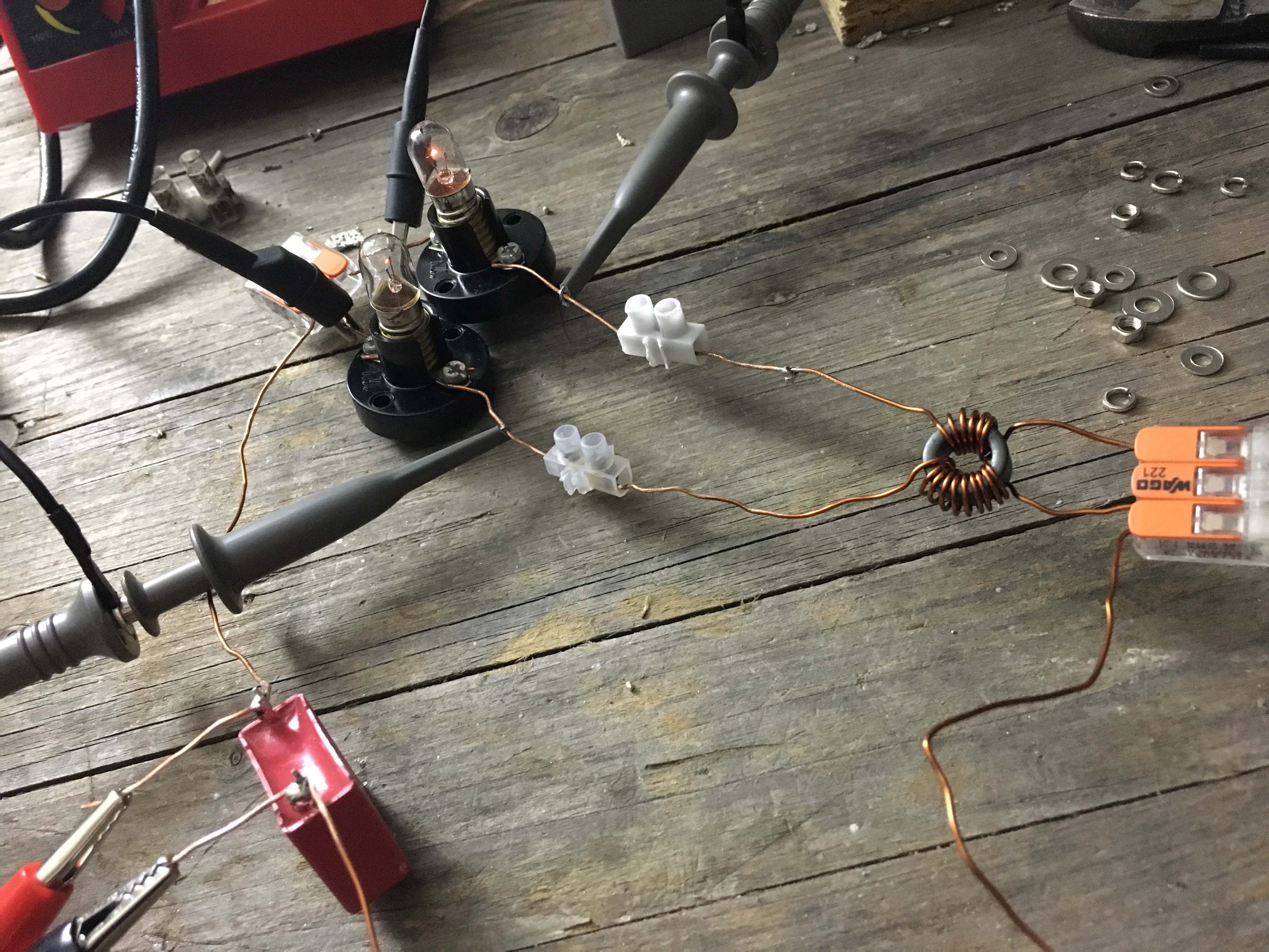
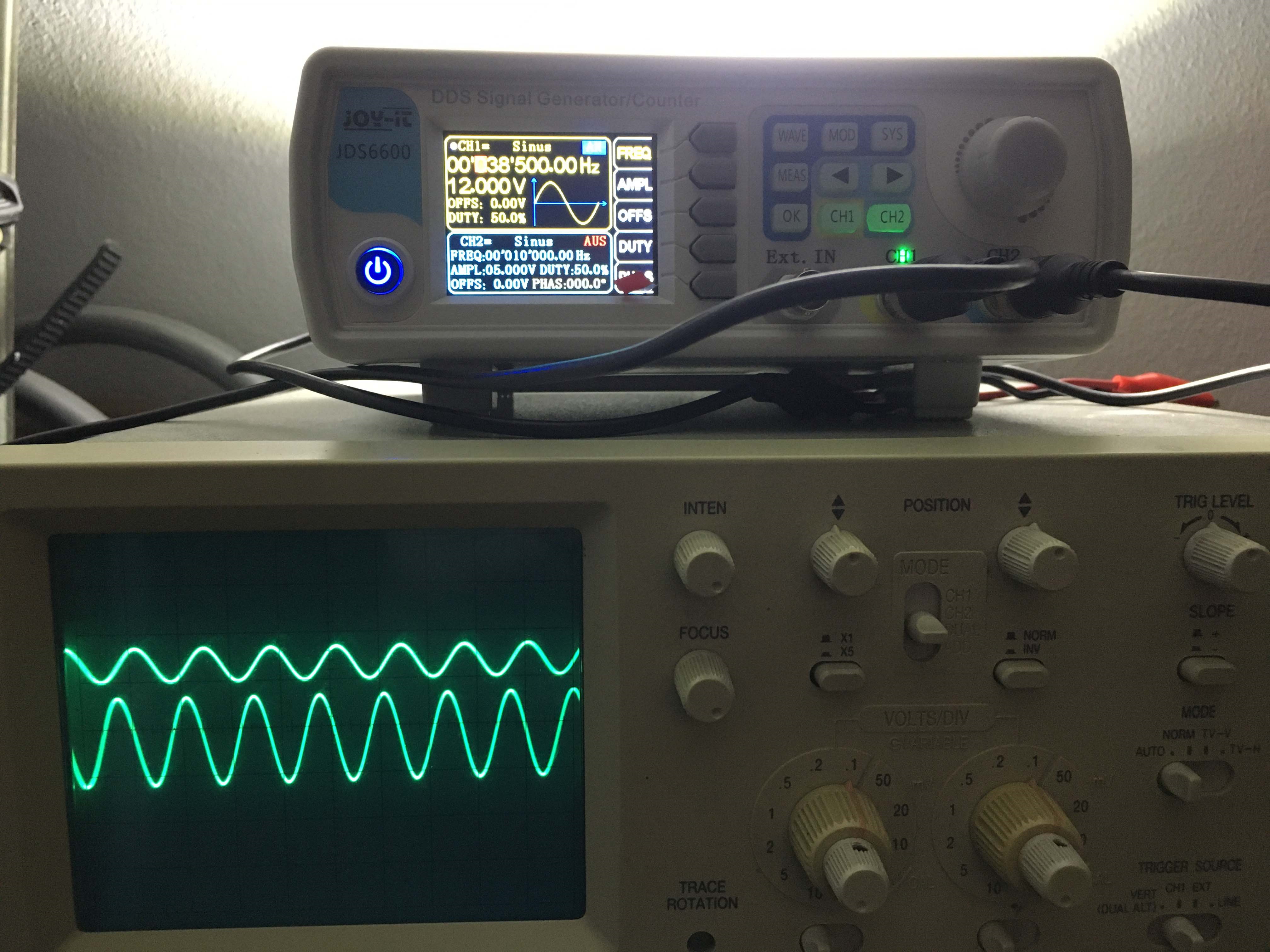
here is my replication of the Mr. Preva Experiment. 

coil: 17.1uH, cap: 1uF --> res. frequency of about 38.5KHz

But as you can see, I was not able to get the lamps glow on the 38.5KHz but on a much lower frequency - and so no resonance. By using just resistors (each 1Ohm) instead of lamps, I almost got the currents to 180° out of phase (last two pictures)

setup_lamps

oscilloscope_lamps

setup_res

oscilloscope_res

I know, I´ve missed something. But I don´t know what...

Dennis

John posted this 11 December 2020

Hi Jagau,


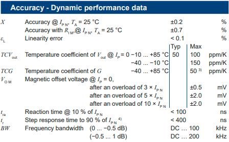
Hall sensor which I used in Mr. Preva experiment is from my old simply measurements and was connected to MCU to digital processing. I was only interested in the waveform and the phase shift at the input to the circuit, so I wasn't interested in accuracy.

Its LEM manufacturer and LTS series

You must be careful to avoid overloading and saturating the core.

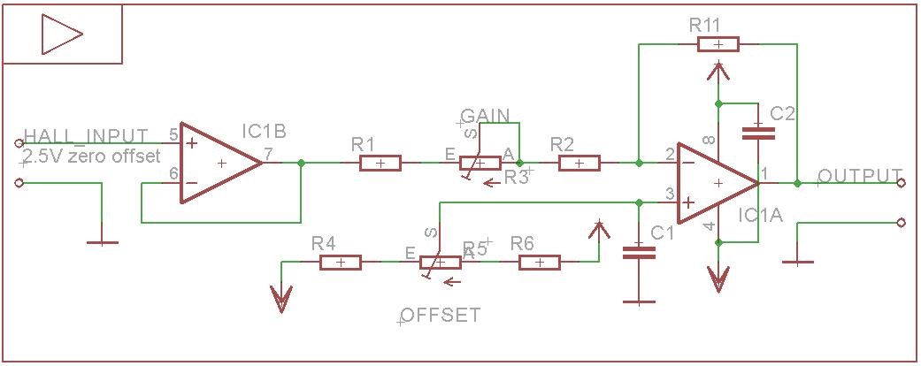
Now I am working on smal circuit to improve hall sensor accuracy. Simple system to setup zero DC offset and gain of the hall. It could looks something like this (probably its not complete). Power supply must be thermaly stabilised.

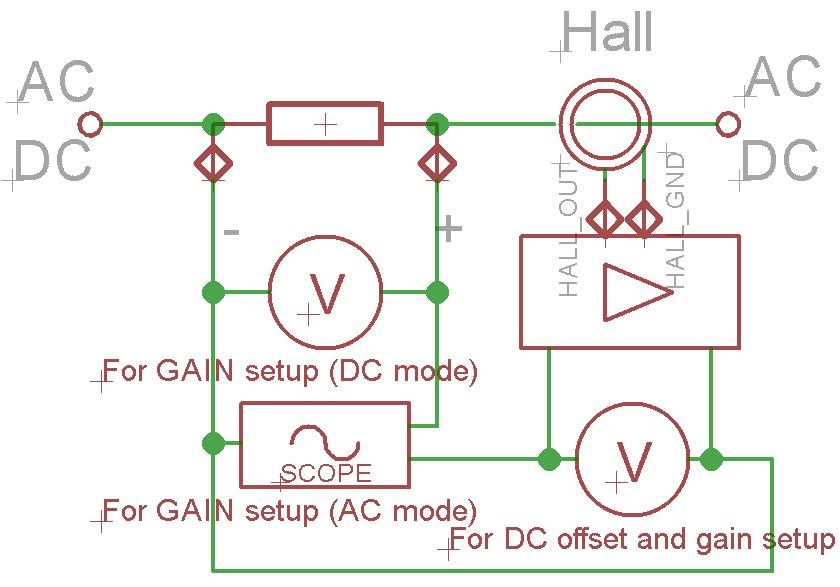
And process of calibration could be like this

If you have any other ideas, come here with them wink

Have a nice day.

John


Jagau posted this 11 December 2020

Hey john
Nice demonstration
Did you build your own hall effect probe?
It probably has a precision up to Max 20 khz?

I have already made a probe like that tell me how did you do the calibration, it was the most problem, it interests me
It is very well done
Thanks for sharing your experiment


Jagau

John posted this 10 December 2020

Hello everybody,

I am attaching my Mr. Preva experiment. 

Everything is shown in the pictures and in the video at the end.

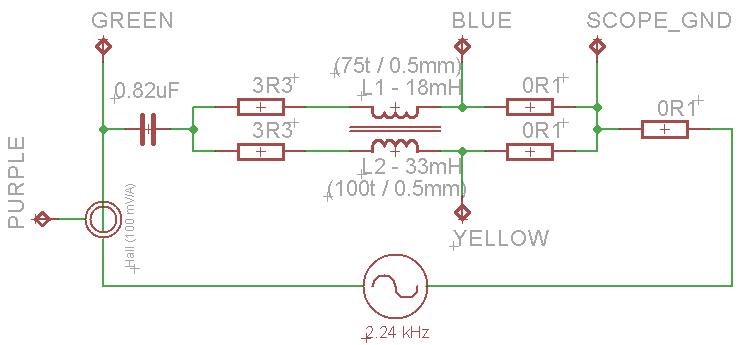
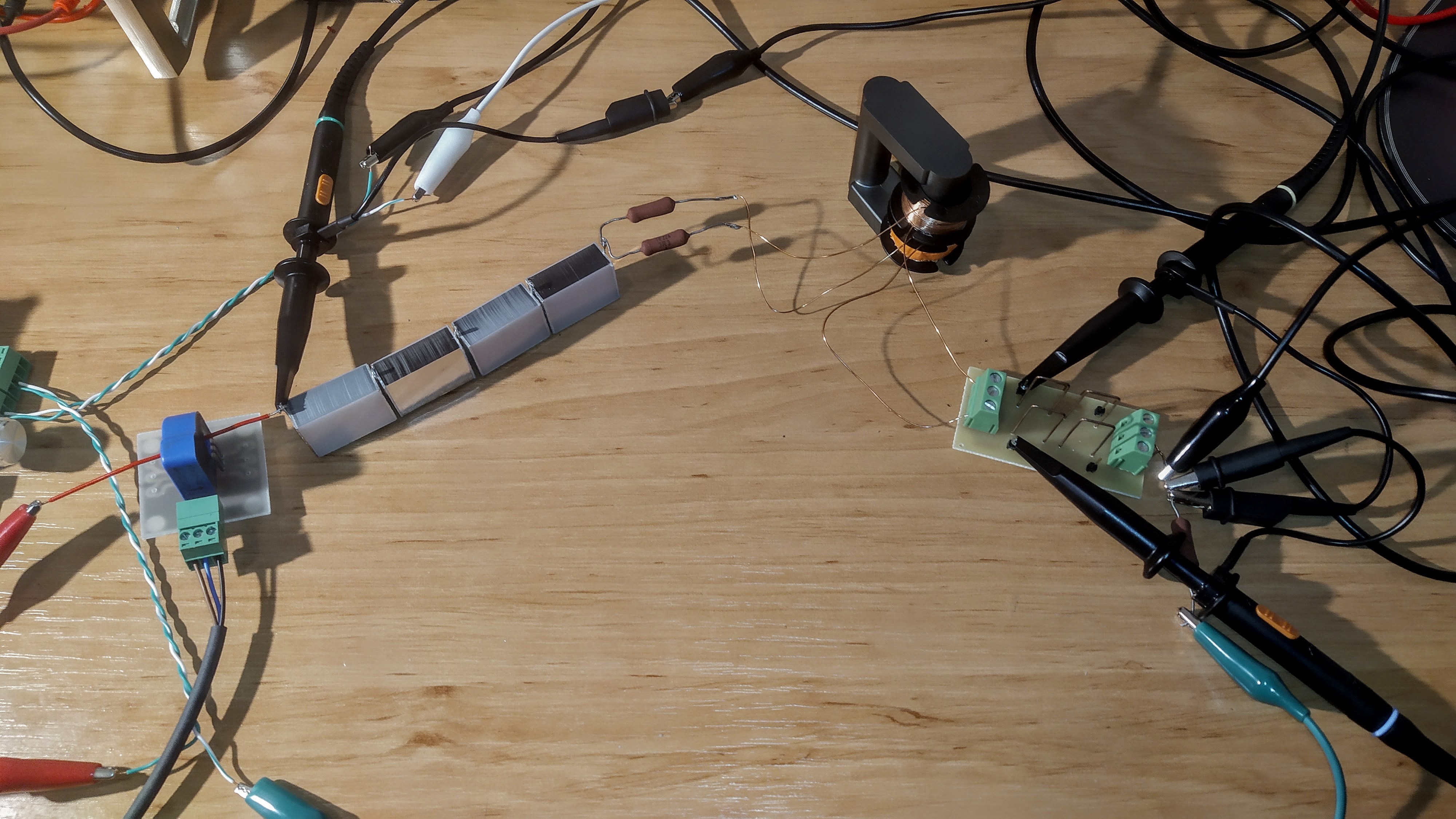
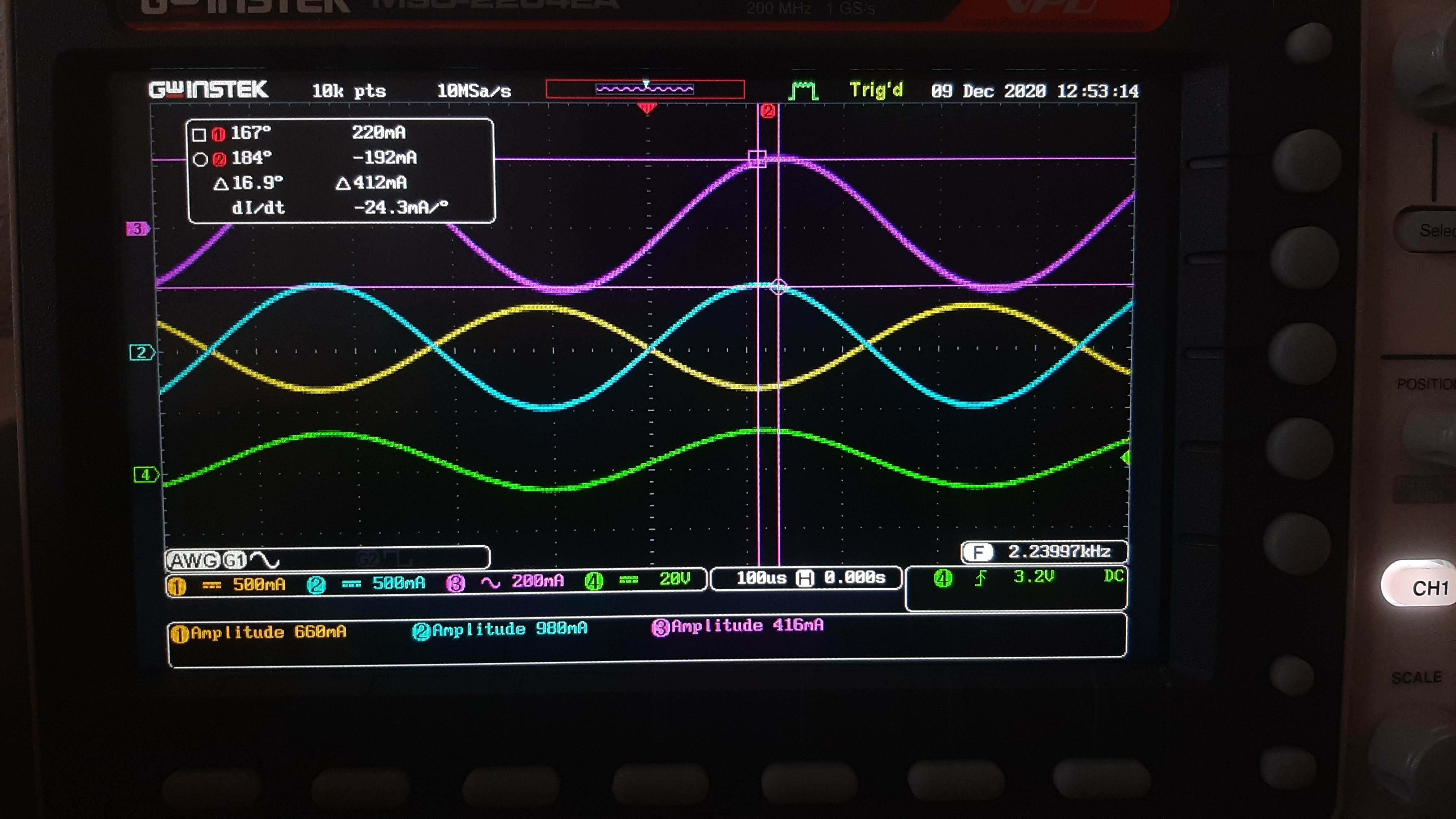
I measured the currents of both coils through 0R1 resistors and I used a hall current probe at the input to the circuit. As you can see in the video, changing the inductance also changes the phase shift. 


And the result of the measurement


Scope measurement:

Blue - current L1

Yellow - current L2

Green - input voltage

Purple - input current

Have a nice day.

John


AlteredUnity posted this 09 October 2020

Think this is the right thread, used pulsed DC, you can see output on buck converter is 80mA(bottom left), and current measured through 1ohm resistor is 240mA. May have few things connected odd, but threw together pretty quick.

Attached Files

Chris posted this 06 March 2020

Hey Andrew,

CD is right. More turns can also help, but you should still get a result with that once you find the right Frequency. This is great to see! People taking on a challenge! Others, here, helping and mentoring! I am very pleased to see! Thank You guys for sharing and helping!

There is lots to learn here Andrew, keep up the good work! If you can post a video , we can help further.

Best wishes,

   Chris

Andrew posted this 06 March 2020

Hmm... 

Only a marginal difference in brightness... 

Not enough volts? Or turns? Or both?

Need a new multimeter - just realised i cannot measure AC amps... 


  • Liked by
  • Chris
  • Augenblick
Chris posted this 10 November 2019

Hey HP,

Yes, three Current Measurements need to be taken:

  1. Input to Coils.
  2. Coil one.
  3. Coil Two.


I hope this helps.

   Chris

  • Liked by
  • cd_sharp
  • Augenblick
Himaliayan Phonix posted this 10 November 2019

Thank you Chris yes I need to measure the current , I will measure and do more analysis, by the way you mean to measure current on the coil with less turns right ? ( in my case It's the one on which the lamp is more brighter)

Chris posted this 10 November 2019

Hey Himaliayan Phonix, HP for short ok?

If you measure the Currents, you should get close to 2x the input current. This will tell you if its right, I am sure it is, as the globes are showing this.

   Chris

Himaliayan Phonix posted this 10 November 2019

Thank you Chris , can you look at the attached picture and tell if I have done it right ?

Chris posted this 10 November 2019

Good to hear Himaliayan Phonix! Sine is normally the best wave shape but most will give varring effects.

Keep up the great work!

   Chris

Himaliayan Phonix posted this 10 November 2019

Hello everyone I also tried to do the Mr.preva replication and it seems to me that I have got the effect where one bulb on one coil is brighter and the other bulb on the second coil is weak in iluminus, I don't have scope to see the waveforms. The effect is critical to frequency and duty cycle, I am still trying to understand what's going on the circuit. The bulb is brighter on the coil which has less turns. I tried sine wave and triangular wave but didn't found the effect, the effect I only found on squarewave, Am i going to the right direction or am i barking to the wrong tree ? Core = TV Yoke ferrite CW coil = 16 turns CCW coil = 26 turns Frequency = 12.51 Khz Square wave Switching voltage 12v Amps consumed 0.88 Wire used = 2.5 mm

Attached Files

YoElMiCrO posted this 19 September 2019

Hello everyone.

Due to lack of time I could not continue with the experiments.
For now I will read the new posts to catch up.
If I have dedicated time to understand what happens in
the fordward topology which is the same more or less than
Preva's experiment but only in the first quadrant.
Using KLC together with EM is that the behavior is understood.
In the first time I have I will publish what happens to me in
both circuits.

Thank you all in advance.
YoElMiCrO.

solarlab posted this 16 September 2019


Hi Chris,

Before deleting these "off topics" - please, try this first:

  - download LTSpice from Analog Devices and install;
  - brifely scan the Help file, then read the FAQ (bottom of Help) > Simulating Transformers;
  - get the "bulb.asc" file (previous link) - use it in a Hieararchy schematic (probably easiest initially);
  - create the "MrPreva" schema and simulate (transient, AC and DC), sweep over freq range, vary pulse width.
  - if you want, - screen capture and post the results (schematic plus various current and voltage probe waveforms).

After that brief exercise, delete all these "off topic" posts!  Then I can just quietly move along into the night... without commenting about reading and absorbing...

Regards,
SL

Chris posted this 15 September 2019

Hmm, interesting reads...

I get some members don't get enough time to read and absorb some threads here. 

I have been through times of frustration also, same as I see in some posts.

Let me say this: To follow in the path of the greats before us, we must put their shoes on.

Ask simple questions, look for answers, has everyone read the Floyd Sweet Papers? Has anyone read the Andrey Melnichenko works? Has everyone read the Don Smith works?

What are the similarities of these same works?

We need to be detectives, use analytics to measure our experimental success and failures. This gives us direction!

I think we could remove a portion of the last posts, it is quite off topic?

   Chris

patrick1 posted this 15 September 2019

Solarlab i hear you on the lack of results. -  i just had another set of failed experiments, with the highest resistance coils ever.,  660ohms an 230ohms pair.  - i dont mind failing, - my problem is, that i am not learning anything from them,  i have no path too victory via my own work with bucking coils.   lots of excitement and theorys  too test. - but its hard too keep going with no real goal,  just shooting in the dark.        my metglas has arrived, and im going too be trying the same kind of things with that. - but honestly i still have no idea what i am doing.....     i guess i take the disheartenment on the chin, its all for a good cause.  but hard too keep doing, especially with what seems like fantastic resources here being in such great abundance ;=)   nows the time....

  • Liked by
  • Augenblick
Vidura posted this 15 September 2019

Some do experiments , some investigate or develop theories and others works on engineering or building solutions and designs and again others want to bring a readymade device on the market. The last task might not be possible until the time is right. This is all OK, that is the way things are happening, we should thus act as a team and each one do the best in his possibilities according to his skills and knowledge, and respect and support those who work in a different field. Personally I dont have much mathematic knowledge, but I try to catch up a little, or I seek help sometimes, as I found it to be a useful tool in occasions, but I also agree that things are tend to be overcomplicated and attempted to  be explained in large structures of formulas , although that the very same concept might be erroneous. Sorry if I got off topic, feel free to delete Chris.

Regards VIDURA. 

  • Liked by
  • Chris
  • Augenblick
solarlab posted this 15 September 2019

Vidura - excellent observations (very good points for sure).

Briefly; Spice type simulators generally provide three analysis:

(1) Transient - Non-linear Time-domain Analysis, where components are represented in differential or integral form. Spice performs an Ordinary Differential Equation (ODE);

(2) DC Analysis, reactive components are treated as shorts (inductors) and opens (capaitors);

(3) AC Analysis, complex admittance replaces real conductance, capacitance becomes jvC and inductance 1/jvL.

BUT, a changing Magnetic Flux (Faraday's Law of magnetic induction *) affects the Branch Equations which breaks Kirchhoff's Voltage Law - the electric field becomes non-conservative (voltage is undefined).

Therefore; an Electromagnetic (EM) solver is needed.

Ref: http://www.emcs.org/acstrial/newsletters/summer09/HowSpiceWorks.pdf


Jaqau - We hear this "quote" over and over ,but take note that none of these experimental scientists developed any theories , so, obviously non of their non-existant theories were erroneous. They merely reported their observations - Tesla included.

Others thankfully did develop theories and backed these up by showing the mathematics, physics and experimental data. These are the theories we use today for useful application.

Not to be harsh or obtrusive, but we have seen many "OU observations - coils lighting light bulbs on Youtube" for well over 10 years and it has all resulted in, well, "0" - z e r o !

We've also heard lecture after lecture from many self proclaimed experts in the OU field telling us how it all works by simple hand waving and such - no math or real science; only their profound chatter and sometimes even convincing ramblings, but without any engineering, mathematics. physics or other science that would be of value for replication or further design effort.

Just - IMHO of course...


  • Liked by
  • Augenblick
  • Vidura
Jagau posted this 15 September 2019

I prefer to quote Tesla on the last words;

Today's scientists have substituted mathematics for experiments, and they wander off through equation after equation, and eventually build a structure which has no relation to reality. . . . 

     The scientists from Franklin to Morse were clear thinkers and did not produce erroneous theories.  The scientists of today think deeply instead of clearly.  One must be sane to think clearly, but one can think deeply and be quite insane. . . 

     The scientific man does not aim at an immediate result.  He does not expect that his advanced ideas will be readily taken up.  His work is like that of the planter—for the future.  His duty is to lay the foundation for those who are to come, and point the way.  He lives and labors and hopes.


It summarizes my thoughts

Jagau

Vidura posted this 15 September 2019

Hi SL and All following, Indeed this circuit is a valuable exercise where a lot can be learned, Until now I haven't discovered anything abnormal anyway, all the behaviour can be explained with Faraday's induction Law, also the simulation should run ok provided that you take out Kirchhoff's law, which only applies in the specific case that d/phi =0 Regards Vidura.

  • Liked by
  • Chris
  • Augenblick
solarlab posted this 15 September 2019


Why focus on the "MrPreva Experiment" as an example beginning CAE Analysis target?

Well, several reasons:

First - the circuit is about as simple as it gets.

Second - after dozens of pages of information, speculation and experiments there does not appear to be any "real technical stuff" presented with respect to the actual circuit, it's potential, nor it's actual operation and why it does what it does (if it actually does anything extra ordinary).

Third - the circuit quickly evolved into a variety of off-shoot circuits and configurations with accompanying claims of various sorts. But, still no concrete postulations or viable explanations of the circuit's operation with support data.

Fourth - the "MrPreva Experiment" will hopefully present a starting point for the introduction of CAE Analysis into the general subject which will further provide another method, or tool set, for discovery. While pointing out ways of clearly understanding and evaluating.

Spice analysis is a mature accepted technique used by millions of designers and, as such, there are litterly thousands of proven resources to draw from. Many of the Spice simulation packages are free and include professional grade features so it's a very good "next step!"

Fifth - Spice CAE provides an excellent pre-cursor to advanced Electromagnetic FEA analysis which will ultimately be required to fully discover and implement the advanced "excess energy" devices of the very near future.

Notice that no canned circuits or cooked examples are provided here - that would quite simply defeat the purpose IMHO!

SL

solarlab posted this 15 September 2019

"MrPreva" Circuit

Should anyone be interested in a Spice simulation of the "MrPreva Experiment," here are some links of interest, including a Light Bulb LTSpice model file:


Paper - "A SPICE compatible Behavioral Electrical Model of a Heated Tungsten Filament"
https://wwwee.ee.bgu.ac.il/~pemic/publications/conf004.pdf


Lamp Spice model: [see the "my_model_files" directory...]
http://ltwiki.org/index.php?title=Adventures_with_Analog


Related: "Use Light Bulbs as Current Limiters?" [also see comments]
https://www.eetimes.com/author.asp?section_id=36&doc_id=1331961#

Might provide some further insight into this highly touted, "MrPreva," anomoly of modern science, circuit!  wink

Have fun and happy experimenting!


PS: Example - A partial list of some magnetics Spice models that are available on-line:

Toroidal Coil on OrCad Pspice
https://electronics.stackexchange.com/questions/237223/toroidal-coil-on-orcad-pspice

Using Coilcraft's Advanced Models in LTSpice
https://www.coilcraft.com/modelsltpice.cfm

Transformer Model in LTSpice – Step by Step Guide
http://electronicsbeliever.com/transformer-model-in-ltspice-step-step-guide/

LTSpice Circuit Simulation Tutorials for Beginners
http://electronicsbeliever.com/ltspice-circuit-simulation-tutorials-for-beginners/

SPICE modeling of Magnetic Core from Datasheet
https://www.youspice.com/spice-modeling-of-magnetic-core-from-datasheet/

WURTH ELEKTRONIK Magnetic components
- Spice libraries (many {huge selection by part #} - LTspice, Pspice, etc...)
https://www.we-online.com/web/en/electronic_components/produkte_pb/bauteilebibliotheken/ltspice/ltspice.php?blank=
- General components
https://www.we-online.com/web/en/index.php/show/media/06_passive_components_-_custom_magnetics/toolbox/Finished_Goods_Catalog_2019_E-FILE.pdf

Amidon toroids
http://www.amidoncorp.com/iron-powder-toroids/


Attached Files

  • Liked by
  • Chris
  • Augenblick
solarlab posted this 10 September 2019

Hi Parkham,

There is a variety of information and videos regarding the "MrPreva" circuit in this thread - scroll up to the beginning for a good review of the subject.


Of interest is the observation where it appears there is a circuit current in the forward direction of 2.8A, a second current in the forward direction of 5.1A  through the top torroid winding; but most interesting is an apparent reverse current of 2.3A through the lower torroid winding - in the reverse direction. This is shown in the second diagram in the attached pdf file above.


A typical circuit of similar type is a simple offset BALUN, thus the reverse current observation is (likely) a new "thing." It will be interesting to discover the fundamental details! 


Although Chris and other members know this circuit probably better than most; I do not believe the circiut is developed enough at this point to be of any real practical application. But if the reverse current anomolies have merrit, then there might well be some interesting and useful off-shoots - as seen in the simplified current diagrams!


Note that this is but one of the many potential "excess energy" concepts being explored here at AU; however there are a few real proofs that have now been demonstrated. My primary quest, and that of many other investigators here, is to develop a generalized theoretical basis, including the mathematics and experimental evidence, for these "excess energy" devices. Without a viable theory we are still in the dark for the most part.


A "valid" parts list will ultimately result through the detailed schematic needed for simulation analysis; so hold off a bit until the schematic is CAE validated or, at least, shows some promise.

Have good one, SL


Chris posted this 10 September 2019

Hi Parkham,

Similar to Benitez - I would say no from what I know.

Many videos and circuits on this thread, you can replicate as you wish.

You will need:

  1. Two Coils, one with less turns than the other.
  2. One AC Capacitor.
  3. Sine wave Function Generator.
  4. Audio Amplifier.
  5. Wire to connect.
  6. Time to replicate.
  7. Help can be found here.


I hope this helps!

   Chris

  • Liked by
  • cd_sharp
  • Augenblick
parkham posted this 10 September 2019

Other questions:  Is this similar in some ways to the Benitez device or Bedini SSG?

  • Liked by
  • Chris
  • Augenblick
parkham posted this 10 September 2019

I came here two years ago, and for whatever reason forgot about Mr. Preva. And for whatever reason, like an itch in the back of my mind, I couldn't scratch it.  So, here I return.  I'm pleased the site is up and active.

I want to do a replication.  Consider the following:  

I have basic electronic skills.  I like visuals as well.  I don't have stuff lying around, as it were.  Would someone please supply me a parts list and point me to a replication video?  I also want to know if I can use this device to keep batteries charged.  I would be honored to make a donation to the Patreon fund after I confirm the technology is real, and useful. 

Thank you,

solarlab posted this 09 September 2019

Hi Fellows,

Since it appears the "MrPreva" circuit efficiency (<1, 1, >1) question still remains unresolved, further analysis might be in order.

Having not followed the discussion closely a quick review of this thread leaves me with these conclusions:

Although a relatively simple appearing circuit; this combination of components may have some hidden effects that warrant further analysis and study according to several investigators.

NOTES:
1. it is unclear at this point whether the V1 generator is Sine Wave or Pulsed.
2. However one video shows a pulsed source at f = 23.5 kHz with 37.5% duty cycle.
3. There are a lot of posts that show an effect of one bulb brighter than the other.
4. However, there are also a lot of posts where the "effect" is not seen.
5. Several "claims" of up to 130% and 140% efficiency are also reported.

Therefore; it might be worthwhile to investigate the "MrPreva" circuit further in more detail. This circuit does NOT appear to fall into either of the two n2 basic catagories (non full-cycle or asynchronous) so, does the "MrPreva" circuit present yet another excess energy anomoly - is something "hidden" within it's configuration?

Maybe we can find out!

A rough draft "semi-formal investigation" proposal is attached.

If any of you fellows have simulation, analysis, detailed coil data, MC12 schematic, or other information that would help shed light on this circuit please share it. Also, if you have access to a "Spice model of a light bulb" that would be very helpful.

Thanks,  SL


Attached Files

  • Liked by
  • Chris
  • Augenblick
Chris posted this 24 August 2019

Hey Patrick,

I do not mean to be a party pooper!

I hope your results prove me and my results wrong! Good luck!

   Chris

patrick1 posted this 24 August 2019

Hello Chris I understand your position,.  however i do stand by my test results at this stage.  please allow me too prove myself wrong, rather than trust the prevailing winds.

i sincerely hope too be able too prove myself wrong, thus learn something more important than free energy !!. taking competent measurements and living up too my training and military certs.

MAKE no mistake though, - this place has wonders beyond the realms of mortal men. ... that i am only beginning too understand.. let us grow together, - and know that i definitely accept the possibility that i am wrong. but it would be a world first.

Chris posted this 24 August 2019

My Friends,

Atti has a point, as do others here.

@Patrick - I have done The Mr Preva Experiment about forty times and all my experiments, as it stands, are all Under-Unity.

Supporting Figures are a recent Rule we termed - IMPORTANT NOT TO MIS-LEAD OTHERS.

New Rule: Any COP > 1 Claims must be accompanied by Measurements please!


The Mr Preva Experiment as it stands is Symmetrical - There is no Asymmetry to it! It is impossible to get Above-Unity figures from a Symmetrical Machine! Input = Output - Losses!

The Machine must be Asymmetrical to get Above-Unity Figures. With some modifications to the experiment one can get Above-Unity Figures, so again I ask you, present your figures if you have done the math and we can write it up.

I am sorry but this is important! Getting a reputation for a bunch of BS in our pages is not the goal here!

In the decades been, haven't we seen enough wrong doing by Traitors of Humanity! Most of us here know who I am talking about! Lets be better than that!

   Chris

  • Liked by
  • Vidura
  • Augenblick
patrick1 posted this 24 August 2019

Hi Atti, good question my friend, - i actaully seem too recall my best mr preva result was 113% efficiency.  but it is hard too be sure.  - although i am as sure as i could be. - analog meters are very good for this kind of range.

still a facinating results. and i am building on it as we speak, be sure i will share my results ;=)..  also please note, all my previous results were using an audio amplifier, - i was unable too get those results with a square wave. - however i am working on that as we speak,... very important since audio amplifiers are very limited in frequency.

  • Liked by
  • Chris
  • Augenblick
Forelle posted this 01 August 2019

Hi Patrick,

how do you came up with 140%?

26,93 divided by 26,6%=1,012

and due to measurement errors i am sure it is under 100%

Have a good day

Atti posted this 21 July 2019

patrick1


i think i got about 130% efficency,


Can we see something more about this?

patrick1 posted this 19 July 2019

Forelle, well done !! i think its amazing.  - also my Preva was successful too !!. i think i got about 130% efficency, , nearly as good as your 140%...  so very consistant,  but if you can spot and other improvements that would be amazing too !!.... afterall, the russians have glowing nichrome wire, -  we can have globes. - ....   anyways its only a competition if your coming second !! rawr

Forelle posted this 18 July 2019

Hi everyone,

I think there is no need for a new thread,all i think is that this experiment is not finished because there is a lot more to investigate,the sad thing is that it is much easier for me to built a motor or generator than to actually tune or adjust a device like a transformer.I have no problem with proceeding publicly but i allways think what i am doing  is not intresting enough for others or worth to show.Maybe when i have finished the Mr. Preva Experiment i make my first video.

Have a god day.

Oliver

Chris posted this 18 July 2019

Hey Oliver,

Please feel free to create a new thread for your Device Under Test ( DUT ).

If you wish to proceed publicly, that is?

   Chris

  • Liked by
  • Vidura
  • Augenblick
AETHERIC_MIND posted this 15 July 2019

Hi

Here is a link to the elaborate explanation to this type of negative resistance by Gabriel Kron.

http://emediapress.com/johnbedini/icehouse.net/john1/


''Change is never easy but it's worth inertia''

  • Liked by
  • Chris
  • Augenblick
We're Light Years Ahead!
Members Online:
What is a Scalar:

In physics, scalars are physical quantities that are unaffected by changes to a vector space basis. Scalars are often accompanied by units of measurement, as in "10 cm". Examples of scalar quantities are mass, distance, charge, volume, time, speed, and the magnitude of physical vectors in general.

You need to forget the Non-Sense that some spout with out knowing the actual Definition of the word Scalar! Some people talk absolute Bull Sh*t!

The pressure P in the formula P = pgh, pgh is a scalar that tells you the amount of this squashing force per unit area in a fluid.

A Scalar, having both direction and magnitude, can be anything! The Magnetic Field, a Charge moving, yet some Numb Nuts think it means Magic Science!

Message from God:

Hello my children. This is Yahweh, the one true Lord. You have found creation's secret. Now share it peacefully with the world.

Ref: Message from God written inside the Human Genome

God be in my head, and in my thinking.

God be in my eyes, and in my looking.

God be in my mouth, and in my speaking.

Oh, God be in my heart, and in my understanding.

Your Support:

More than anything else, your contributions to this forum are most important! We are trying to actively get all visitors involved, but we do only have a few main contributors, which are very much appreciated! If you would like to see more pages with more detailed experiments and answers, perhaps a contribution of another type maybe possible:

PayPal De-Platformed me!

They REFUSE to tell me why!

We now use Wise!

Donate
Use E-Mail: Chris at aboveunity.com

The content I am sharing is not only unique, but is changing the world as we know it! Please Support Us!

Thank You So Much!

Weeks High Earners:
The great Nikola Tesla:

Ere many generations pass, our machinery will be driven by a power obtainable at any point of the universe. This idea is not novel. Men have been led to it long ago by instinct or reason. It has been expressed in many ways, and in many places, in the history of old and new. We find it in the delightful myth of Antheus, who drives power from the earth; we find it among the subtle speculations of one of your splendid mathematicians, and in many hints and statements of thinkers of the present time. Throughout space there is energy. Is this energy static or kinetic? If static, our hopes are in vain; if kinetic - and this we know it is for certain - then it is a mere question of time when men will succeed in attaching their machinery to the very wheelwork of nature.

Experiments With Alternate Currents Of High Potential And High Frequency (February 1892).

Close