Transformer Phase shifting

  • 1.4K Views
  • Last Post 17 October 2018
Vidura posted this 24 July 2018

Hi everybody!

For better readability i start a new thread to continue the transformer tests  posted in the Lenz Force free power generation thread.

The goal is to get more information about the influence of windings, core materials and frequency on the fase shifting,

and the posibilities to delay the lenz effect in order to get a positive feedback of flux. 

  • Liked by
  • Chris
Order By: Standard | Newest | Votes
Vidura posted this 24 July 2018

Here some results from a first test with the device used in the reduced reaction transformer test and a comparision with the same core and a standard secondary, the transformer is fed directly with a sinewave, without the resonant capacitor

this shot shows  inpur vs. output voltage with the  standard winding.

here with the RR.transformer winding

Input voltage and current in the RR. transformer.

and in the standard winding


the following shots shows input vs. output voltage with lower voltage level, you can see a different wave shape.

:


Jagau posted this 24 July 2018

Thank you for sharing

Jagau

  • Liked by
  • Chris
Marathonman posted this 24 July 2018

Vidura; It's Phase not fase.

Regards,

Marathonman

  • Liked by
  • Chris
Vidura posted this 24 July 2018

Thank you for the correction, and sorry for my bad English.

  • Liked by
  • Chris
Vidura posted this 25 July 2018

Due to my lack of knowledge on this topic i have performed a test with a standard secondary winding, if somebody can explain me i will appreciate. The following three scope readings are 1. open circuit, 2. loaded 3. short circuited.the upper traces are input  U & I

below the secondary U & I


Unloaded you can see the expected 90° shift  for reactive power, loaded there is an increase in current  and a phase shifting towards the Voltage peak, until here all seems logical, but when shorted the secondary the current peak goes back to the 90° shifted position-reactive power, so a shorted output would not take power from the source?? 

  • Liked by
  • Chris
Vidura posted this 25 July 2018

In this test i have connected a common mode choke connected in opposed coils configuration en series with the primary coil,

here you can see an important increase of the impedance and thus rising of the input voltage.

(in order to get the same output i had to rise the input voltage)

  • Liked by
  • Chris
Chris posted this 29 July 2018

Hey Vasile,

Zero Degrees is Real Power, so on the Secondary ( s ) this is what we want.

However, on the Primary, we want 90 or more degrees, the Power In then becomes the Power Out, thus we use no Power on the Input. All the Input Power, and more, is returned back to the Source for reuse.

Vidura is exactly on the right path - Well done Vidura!

He has shown that the Input Phase angles can be retarded by adding Load, which is reverse to normal Transformers - VERY Important concepts to understand correctly!

Good to see you back, its been a while!

   Chris

Vidura posted this 29 July 2018

Hi, If anyone have a explanation for the behaviour of the transformer when shorting the secondary there seems to be a phase angle of nearly 90° between primary current and voltage, these scope shots have been made with the standard secondary winding at 4khz. Does that actually mean that all power is returned to the source ,in the secondary is real power, as the shorted secondary becomes hot quickly? What about the fees of the electric companies for reactive power, it is said that they want to avoid harmonic distortion on the grid, or might it be that the meters don't work properly?

  • Liked by
  • Chris
Jagau posted this 29 July 2018

hello Vidura
All your answers are in this patent US9230730B2 Bitroidal transformer.

And I could also read on the following topic:
The charge seen by the primary when placing a load on the secondary of a transformer

follow established rules.

Jagau

Vidura posted this 29 July 2018

Thank you jagau I'll have a look on this info.

  • Liked by
  • Jagau
  • Chris
Jagau posted this 29 July 2018

thank you for sharing your experiences Vidura,

all experiences are important, I appreciate, I think we should not be afraid to ask questions, it's how we get better.


Have a good day


Jagau

  • Liked by
  • Chris
Chris posted this 30 July 2018

Hey Guys,


Inductive Rractance: Definition

the opposition of inductance to alternating current, equal to the product of the angular frequency of the current times the self-inductance. Symbol: XL

Ref: https://www.dictionary.com/browse/inductive-reactance


Inductive Rractance is the "Generation" of E.M.F in the opposing direction in the same coil, this increases the "Resistance" of the Flow of Current in the Coil which is commonly known as B.E.M.F or Back EMF.


As the "Generation" of B.E.M.F increases, the Coil becomes more Inductive, or becomes more "Resistive" to the Change in Current. 

Inversely, the Coil is also susceptible to any and all external influences. If the Secondary Coils are "Generating" more E.M.F than is being supplied, and is at the right phase, then the Input Coil's Inductive Reactance will change, and can push the Phase Shift back.


Inductance

Inductance changes with the Magnetic Field. I have shown a really important experiment here. This shows that with an increasing magnetic Field, the Inductance decreases.

This is how the Paraformer works. The Change of Inductance over Time creates an E.M.F.

By making the Input appear highly Inductive at the right time, then the Change in the Output's Magnetic Field sends power back through the Input Coil.

   Chris 


  • Liked by
  • Vidura
Vidura posted this 02 August 2018

Hey Chris ,

when i was looking for info about paraformers i found this image:

  • Liked by
  • Chris
  • Vasile
Vidura posted this 03 August 2018

Hi Vasile Compare this info with the explanation that gives Marathon Man of the part G in the figueras device, the flux is constant ,the voltage is Induced by varying the inductance.

The paraformer is a particular type of transformer. It transfers the power from primary to secondary windings not by mutual inductance coupling but by a variation of a parameter in its magnetic circuit. First described by Wanlass, et al., 1968.

Assuming Faraday's law of induction, it is possible to obtain a voltage at the secondary winding terminals also thanks to a variation of the inductance, so that

d(flux)/dt=d(L*I)/dt

This can be accomplished by for example modulating the saturation of the core by means of an applied variable magnetic field. It works even if primary and secondary windings magnetic coupling is zero (when the fluxes are mutually orthogonal) (Burian 1972, p. 278).

  • Liked by
  • Chris
Vidura posted this 03 August 2018

Regarding the paraformer there arised the question how the power is transferred if there is no inductive coupling between primary and secondary.Here I attach the us patent from Wanlass ltd. where the mecanism of the magnetic circuits is explained in detail.

Attached Files

  • Liked by
  • Chris
  • Vasile
Vidura posted this 05 August 2018

I got somehow curious about the Paraformer, so I built a kind of replication. Here in this testing you can see the basic behaviour regarding the timing and BEMF. What I could not produce is the claimed effect of frequency doubling, maybe due to the core specifications and shape.

  • Liked by
  • Chris
Chris posted this 05 August 2018

Vidura, again excellent work!

An excellent example of how the Change of Current in Time is what one needs to observed.

   Chris

Marathonman posted this 06 August 2018

quote;

"Interesting info. So... if the flux coupling is zero what does transfer the energy?"

The Electric field.

I have 400 hz core in my closet, maybe i should dust them off.

Regards,

Marathonman

  • Liked by
  • Vidura
Vidura posted this 06 August 2018

Hi MM. How is your knee, i hope you're cured. It is interesting this device, I used the ferrite pieces because I didn't have suitable iron cores as the original device uses. Without the capacitor there is no output at all, so my guess is that the oscillations in the secondary sets up the secondary flux, which is modulated by cyclic changing of the core parameters.There is also stated that a portion of cross over flux exists. Would be good to get some results from your 400hz core. Regards Vidura

  • Liked by
  • Chris
Vidura posted this 09 October 2018

Hello Team, As Chris has suggested, soon I will continue the investigations in this thread. I have asked Him to move the thread in this category, but I want to remark that the reason is not to hide it, All this investigations and any Devices that could result from them will be published in the forum open to the public at a later moment, and if for any reason I couldn't do it myself, the team in Tier II can use it and decide tu make it public when they find that circumstances are right. Vidura

  • Liked by
  • Chris
  • Wistiti
Vidura posted this 13 October 2018

Inductive Rractance is the "Generation" of E.M.F in the opposing direction in the same coil, this increases the "Resistance" of the Flow of Current in the Coil which is commonly known as B.E.M.F or Back EMF.


As the "Generation" of B.E.M.F increases, the Coil becomes more Inductive, or becomes more "Resistive" to the Change in Current.
Inversely, the Coil is also susceptible to any and all external influences. If the Secondary Coils are "Generating" more E.M.F than is being supplied, and is at the right phase, then the Input Coil's Inductive Reactance will change, and can push the Phase Shift back.

Hi team,

regarding the inductive reactance it occured an idea to me: In any coil the two adjacent conductors will have the srtongest inductive reactance, now suppose coil where the winding direction changes after each turn, an "inductionless" coil with alternate direction of currentflow , this should give an effect of antireactance, an enhancement of current. You see the similtude in the granadecoil, which would have at least partially this effect. It might be worth to wind such an odd coil and test? Principally it is the inductionless coil, where the magnetic field of  each adjacent turn induces a current in the same direcction as the original current flows.

and in this version the distributed capacitance would be minimized:

  • Liked by
  • Chris
Chris posted this 13 October 2018

Hey Vidura,

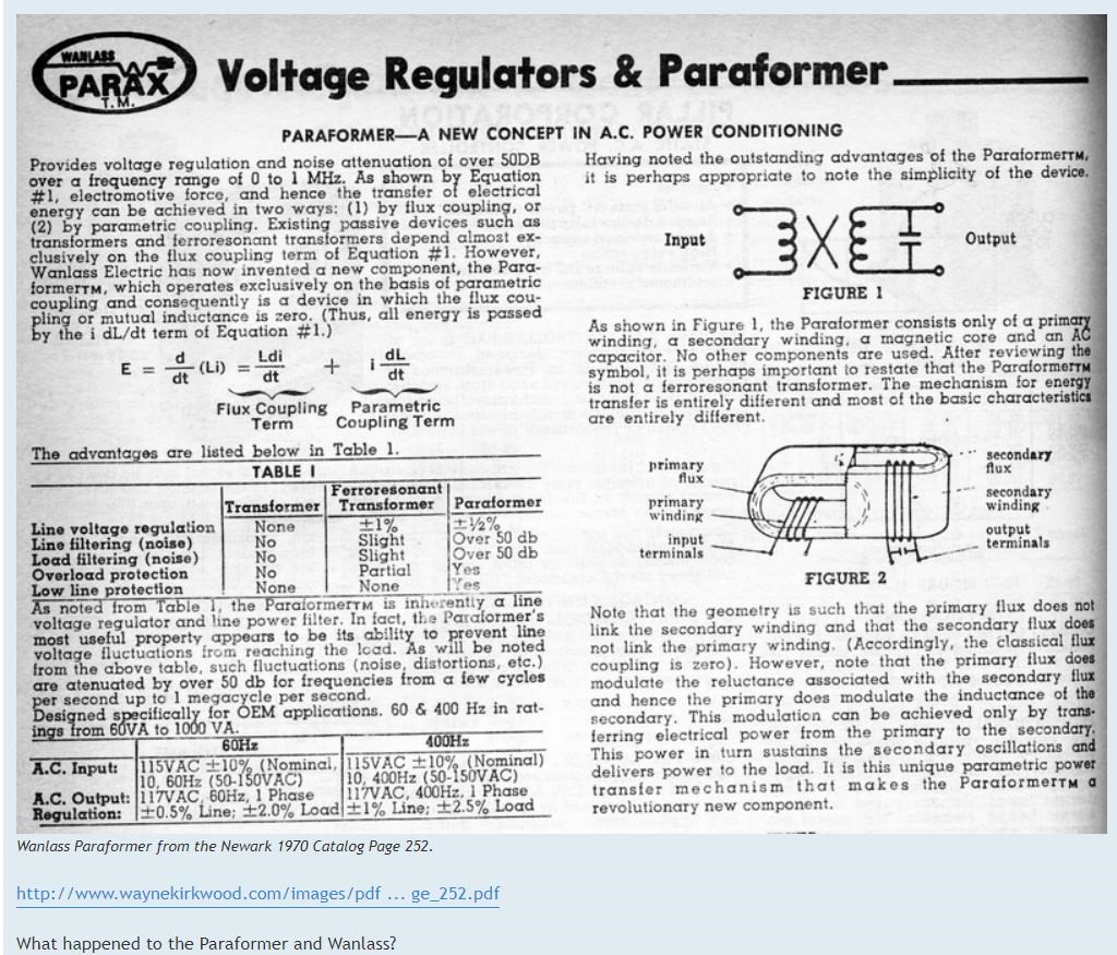
Perhaps a little reading between the lines is necessary here, but generally the quote is true.

As Cycles per-second increases, the Coils "Resistance" to change also increases. This is because the Coil Self "Generates" its own E.M.F in reverse to the applied E.M.F, or B.E.M.F.

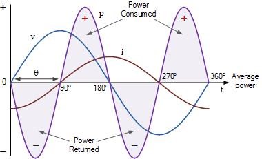
Basically, the Electrical Resistance in an Inductor, when Alternating Current is applied across the Inductor, is called Inductive Reactance XL. This is the Resistance to Change of the Magnetic Field. The reason there is a resistance, is because the Back Electromotive force, which is a self Induced E.M.F as was pointed out, opposes the Forward E.M.F or applied E.M.F. The Forward E.M.F and Back E.M.F cancel each other out.

The Inductive Capacitance, XC is considered to be the Distributed Capacitance, the lack of space between the Turns act as a Capacitor Plate, the Insulation, is the Dielectric.

At Resonance, XL is equal to XC so they effectively cancel. Or perhaps we should say one is no longer dominant over the other any more and we see Resonance due to Distributed Capacitance and the Coils Inductance.

Inductive Reactance increases with Frequency or Cycles per-second: 2πfL


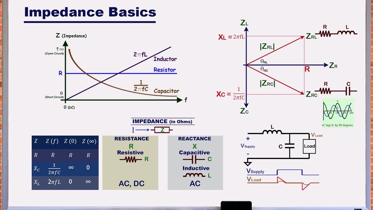
This is because, in Faradays Law of Electromagnetic Induction, the Time Rate of Change ( dt ) is a determinant factor to the E.M.F:

E.M.F = -NdΦ/dt


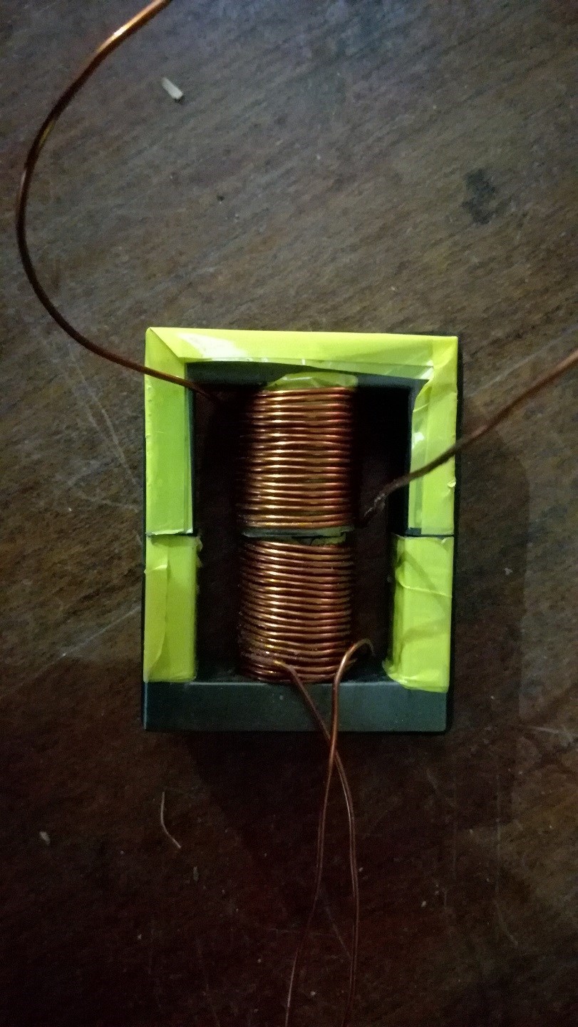
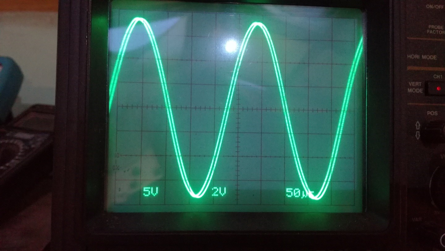
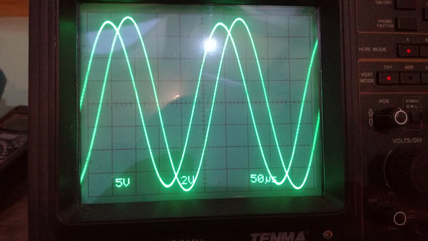
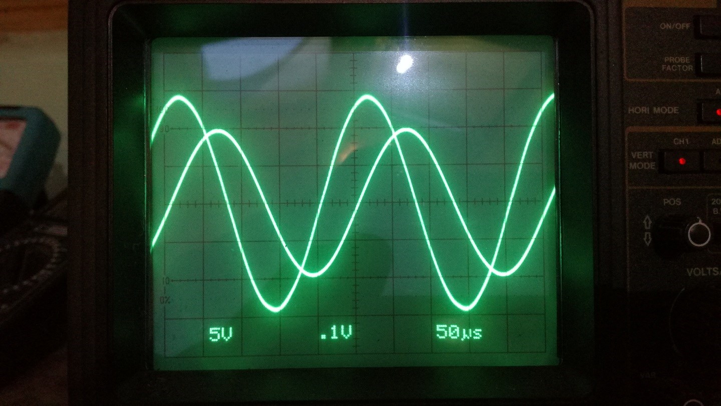
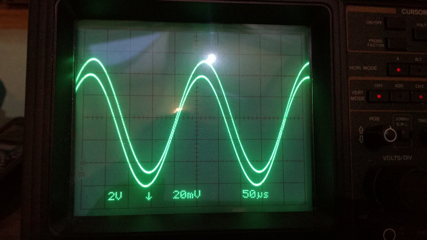
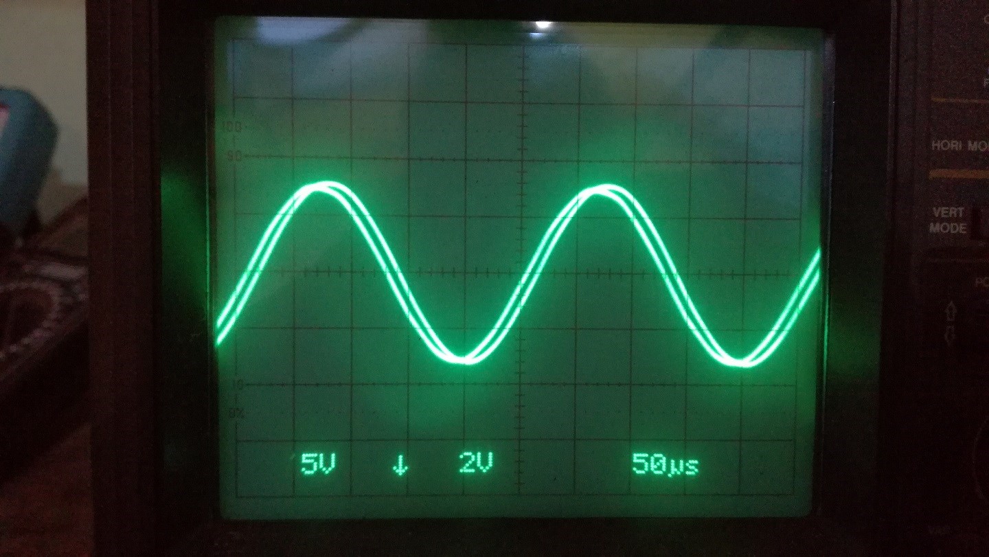
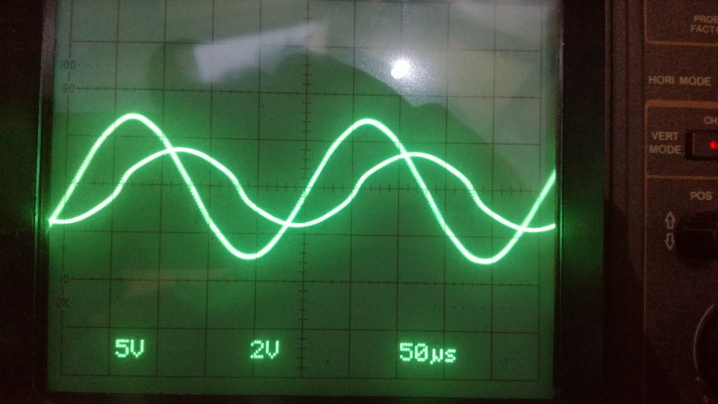
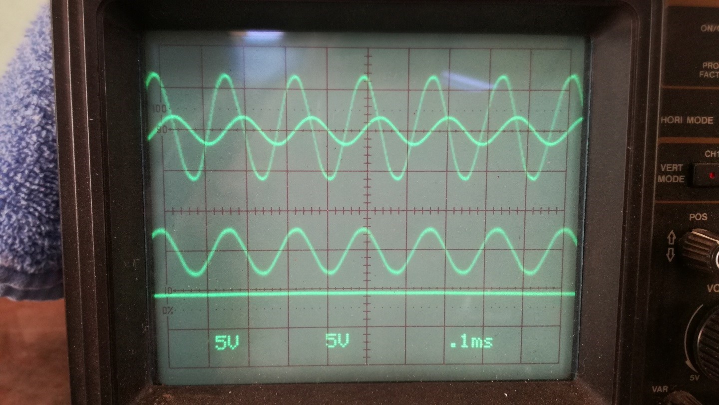
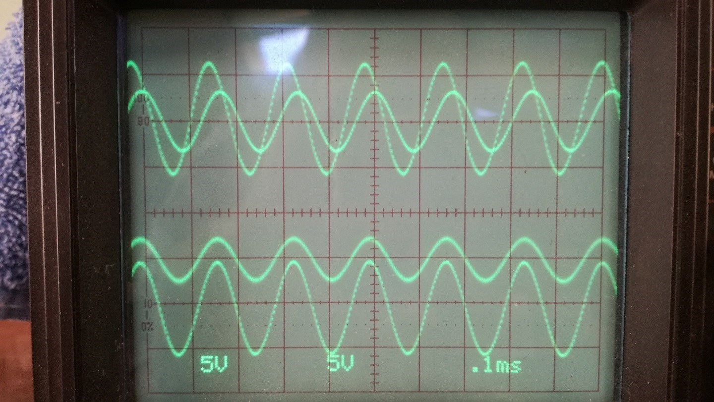
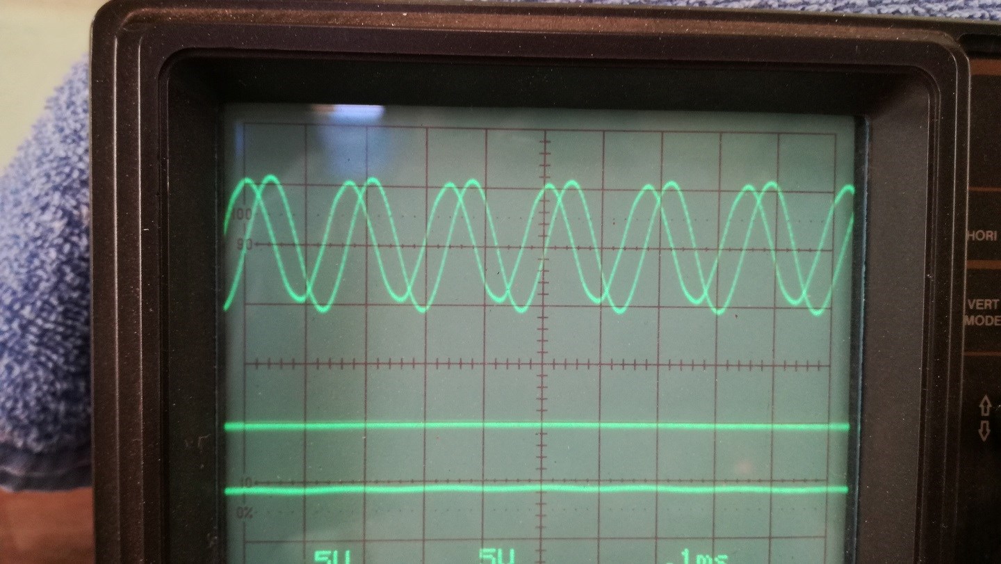
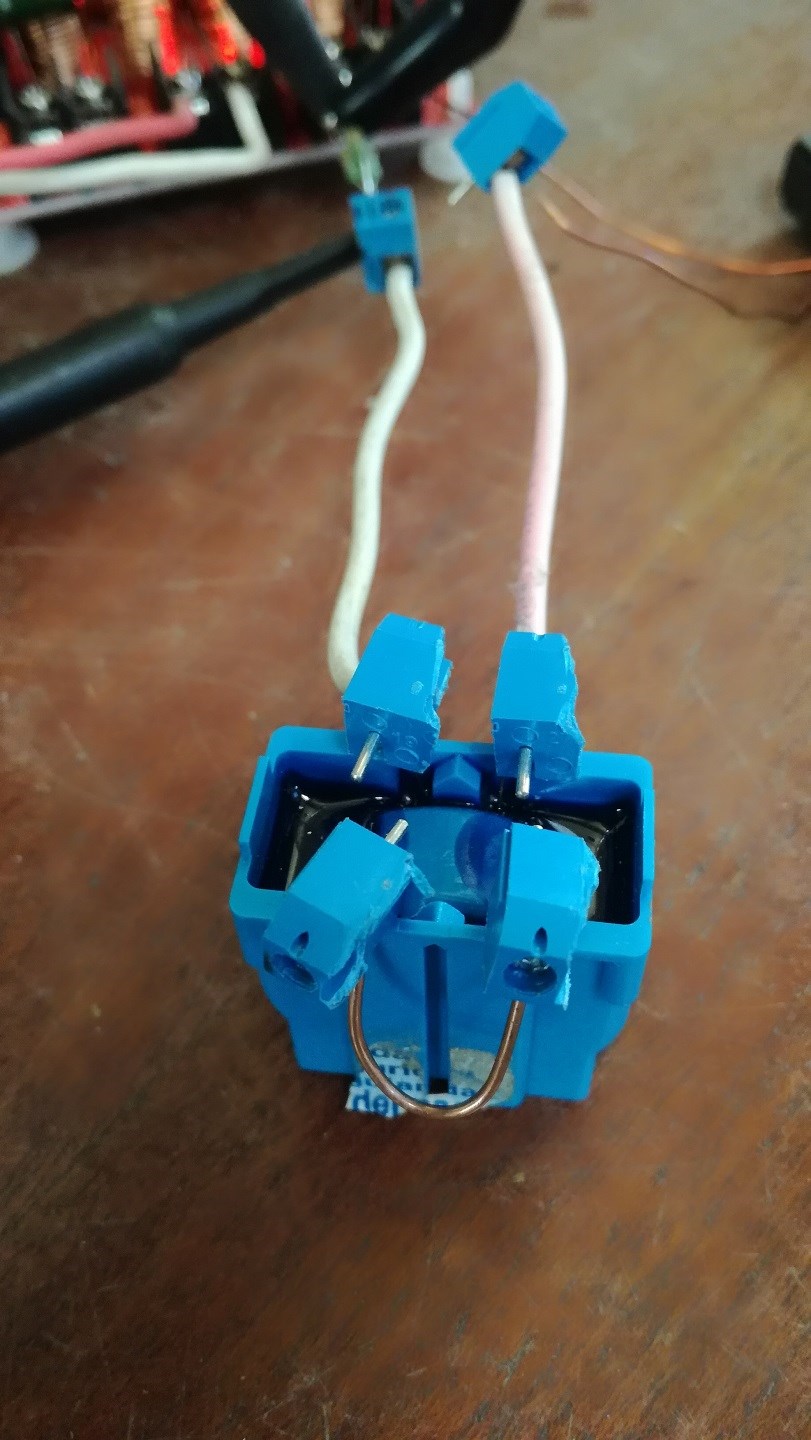
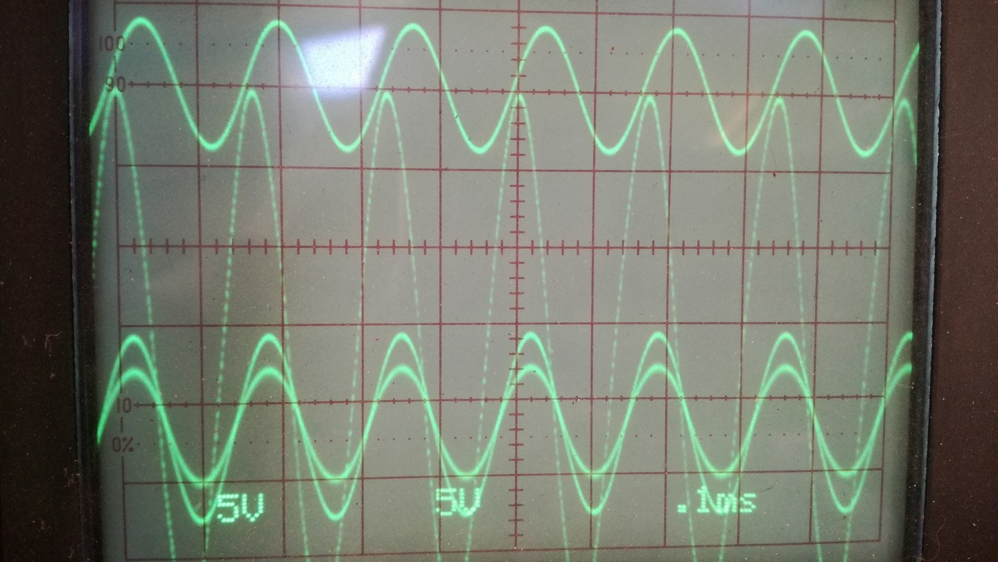
The Mr Preva Experiment is an excellent example of all you have covered.

   Chris

Vidura posted this 13 October 2018

Another application seems to be teslas current amplifiing coil, the bifiliar pancake coil, but with both ends connected together , so the current flowing induced by adjacent turns enhance the current. i meant this configuration:

  • Liked by
  • Chris
Chris posted this 13 October 2018


The Tesla Switch is an example of what I covered:


Battery Charge wants to distribute itself evenly, but with an un-even distribution, we see some unusual effects.

   Chris

Vidura posted this 13 October 2018

Sorry Chris we get off topic,i did not explain clearly the idea, when i come to my pc i'll add som images. Pd.i have done some experiments with the teslaswitch, and basicly it works, anyway the employment of batteries has drawbacks.

  • Liked by
  • Chris
Chris posted this 13 October 2018

Hey Vidura,

I see you have uploaded Images, thanks.

If I may recommend a read of a paper I wrote: Does Science truly understand Electromagnetic Induction?

A Coil can be thought of as a Battery under the right conditions!

   Chris

  • Liked by
  • Vidura
Vidura posted this 14 October 2018

hey Chris , 

I have read your paper, and re-read again, my conclusion is that the current explanation  of science for the EM induction is incomplete, if not faulty. Hopefully our experiments will lead to discover the missing part. 

I also want to add a comment about the earlyer eperiments in this thread:

In the comparision of the reduced reaction transformer with the standard winding transformer (images in the first post)

Note that the" standard transformer" has opposed windingdirections  in primary and secondary, and the core have a 0.5mm airgap in the central leg.

I will make some additional tests changing the airgap size and some other parameters.

Vidura posted this 14 October 2018

Hello, finally back at the bench for some hours. Continuation of the testing of the reduced reaction transformer, here a short Video:


Input is 10V/div output 2V/div currents 0.1V/div resistors 0.11
I was a Little surprised that voltage and current moved in phase when it became resonant,

Edit: It is certainly normal for a LC resonant circuit that the impedance drops to a minimum at resonance, and the power is literally pushed thru the secondary's, there was a huge increment on the output, but all the phasing was gone, and the currents and voltages where(nearly) in phase . I will try some test with parallel LC tank and also with DC pulsing.

  • Liked by
  • Chris
  • Jagau
Chris posted this 15 October 2018

Hey Vidura,

Looks like the video is still uploading, currently can not view, will wait a bit longer.

NOTE: Please remember, if you see 90 Degrees Current to Voltage Phase shift, you're using no Power on the Input, even if the Bench Power Meter says you are!

Most Amplifiers are super in-efficient if they see lots of Reactive power.

   Chris


Vidura posted this 15 October 2018

Some more tests of the RRtransformer

  • Liked by
  • Jagau
  • Chris
Vidura posted this 16 October 2018

Hi team,

with the last tests it becomes clear that it is quite possible to tune a transformer in a way that the input power is reactive and the output in phase. Now the challenge is how to implement this in a practical device. If the transformer could be tuned this way to 50-60hz we could simply "play ping-pong with the grid" to extract free power, but a real solution would be to get such device self-sustaining. Therefore would be needed a special power supply that can handle and recicle reactive power with small losses, and it should be adjustable to the frequency required by the device. The most promising technique I guess would be a tuneable resonant tank circuit.

if someone has suggestions for possible solutions please post.

Vidura

  • Liked by
  • Chris
Chris posted this 16 October 2018

Hey Vidura,

FANTASTIC Results! Very nice!

I did a lot of research on Switching: Reliable and Flexible Switching System

A H-Bridge is the optimal for this sort of work, by far! In saying this an Audio Amplifier is a very good start! I have a few H-Bridges

A Circuit something similar to this may be a good place to work from:


Of course the resulting secondary Circuitry will be quite different!

   Chris


P.S: eBay may have a good H-Bridge to start with?

  • Liked by
  • Vidura
Vidura posted this 16 October 2018

Chris,thanks for the suggestion. 

I just remembered that i have an evaluationboard  for  PMSM motors with a pic32 processor and a tree phase H bridge, it has also high resolution PWM perifericals, could be very useful, but i have to write the C code to convert it in a labtool, and quite a long time i have not programmed MC's.Have to pick up the string again, Regarding the Ebay, I am in Argentine and it is a grain in the backside to  import anything in this country and sometimes very difficult to get specific components,  this is one reason for delaying the projects many times. 

Thanks for the schematic, maybe with an adjustable inductance just what is needed


  • Liked by
  • cd_sharp
  • Chris
Jagau posted this 16 October 2018

Hi Vidura

Power factor corrector in AC circuit is very important to control about our elctricity bill.


Jagau

  • Liked by
  • Chris
Chris posted this 16 October 2018

Hi Vidura,

Jagau is correct!

Power factor corrector in AC circuit is very important to control about our elctricity bill.


Please forgive me if you know this already, but, The power in to your Machine is exactly equivalent to the Power Out of your Machine, on the Input Side, not Including the Output Side, when you see 90 Degrees Phase Shift from Input Voltage to Input Current.

This means you are effectively using Zero Power on the Input: 1 + -1 = 0


See my website: AC Power Calculator

It uses three Variables:

  1. Voltage
  2. Current
  3. Phase Angle


To calculate the variables:

  • Watts or Real Power
  • Volt Ampere or Apparent Power
  • Reactive Power or Volt Ampere Reactive Power
  • Power Factor, a value that should always be between -1 and 1 all sources that say 0 and 1 are wrong!


This should help in your Input Power calculations! Never take whats on the Bench Top Power Supply as your Input Power! Most Amplifiers and similar devices do not handle large amounts of Reactive Power very well and Input is burned as a result, not a factor of your Device Under Test, a factor of Amplifier Design.

Hope this helps my Friend wink

   Chris

  • Liked by
  • Vidura
Vidura posted this 17 October 2018

Hi Chris, thanks to your patient  explanations bevor I do understand now about the reactive power, also how to calculate it when dealing with sinewaves, only when the waveform is distorted and the degrees of  phaseshift is somewhere in between 0 and 90 it becomes difficult to calculate. 

regarding the metering I think the older electromechanically meters dont read reactive power . the newer electronic meters do detect it and the power companies can charge additional fees , which is applied in big consumers like industries actually. in our country at least it is still not applied for final consumers.


  • Liked by
  • Chris
We're Light Years Ahead!
Members Online:
What is a Scalar:

In physics, scalars are physical quantities that are unaffected by changes to a vector space basis. Scalars are often accompanied by units of measurement, as in "10 cm". Examples of scalar quantities are mass, distance, charge, volume, time, speed, and the magnitude of physical vectors in general.

You need to forget the Non-Sense that some spout with out knowing the actual Definition of the word Scalar! Some people talk absolute Bull Sh*t!

The pressure P in the formula P = pgh, pgh is a scalar that tells you the amount of this squashing force per unit area in a fluid.

A Scalar, having both direction and magnitude, can be anything! The Magnetic Field, a Charge moving, yet some Numb Nuts think it means Magic Science!

Message from God:

Hello my children. This is Yahweh, the one true Lord. You have found creation's secret. Now share it peacefully with the world.

Ref: Message from God written inside the Human Genome

God be in my head, and in my thinking.

God be in my eyes, and in my looking.

God be in my mouth, and in my speaking.

Oh, God be in my heart, and in my understanding.

Your Support:

More than anything else, your contributions to this forum are most important! We are trying to actively get all visitors involved, but we do only have a few main contributors, which are very much appreciated! If you would like to see more pages with more detailed experiments and answers, perhaps a contribution of another type maybe possible:

PayPal De-Platformed me!

They REFUSE to tell me why!

We now use Wise!

Donate
Use E-Mail: Chris at aboveunity.com

The content I am sharing is not only unique, but is changing the world as we know it! Please Support Us!

Thank You So Much!

Weeks High Earners:
The great Nikola Tesla:

Ere many generations pass, our machinery will be driven by a power obtainable at any point of the universe. This idea is not novel. Men have been led to it long ago by instinct or reason. It has been expressed in many ways, and in many places, in the history of old and new. We find it in the delightful myth of Antheus, who drives power from the earth; we find it among the subtle speculations of one of your splendid mathematicians, and in many hints and statements of thinkers of the present time. Throughout space there is energy. Is this energy static or kinetic? If static, our hopes are in vain; if kinetic - and this we know it is for certain - then it is a mere question of time when men will succeed in attaching their machinery to the very wheelwork of nature.

Experiments With Alternate Currents Of High Potential And High Frequency (February 1892).

Close