Akula's circuits- is this the principle?

  • 10K Views
  • Last Post 19 November 2020
Vidura posted this 03 September 2018

Hello Team, after watching one of Akulas videos several times(Trance and Resonance) I think to understand a little bit better the principals of operation, and so I will share this observations here, hopefully adding up some useful information. Specially this circuit which is quite simple seems to be good to grasp the principle how it works, and also is cheap and quickly for built, in order to try to replicate.

Edit: viewing the valuable information about andrey melnichenkow that Chris has posted it becomes obvious that the credits for this discovering and buildings are corresponding to him ,and not to Akula, who evidently has merely copied Andrey's work.

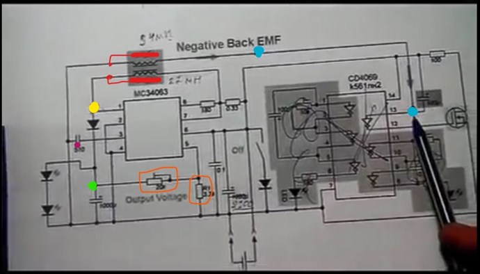
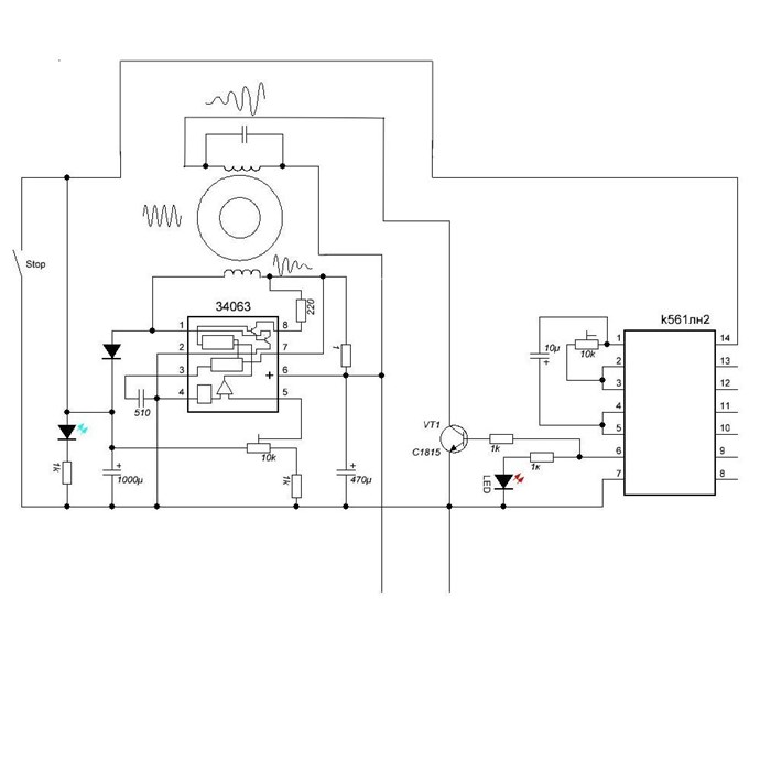
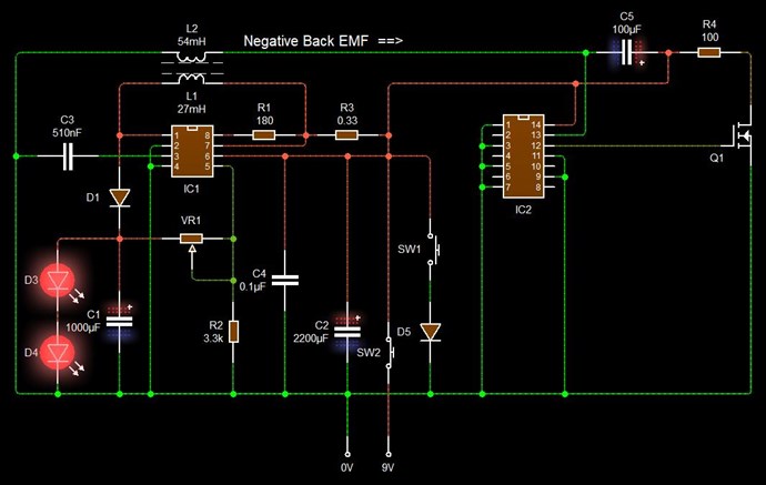
This is the schematic he is explaining on the video, I'll post the relevant details: the test points are highlighted in the colour of the scope traces.

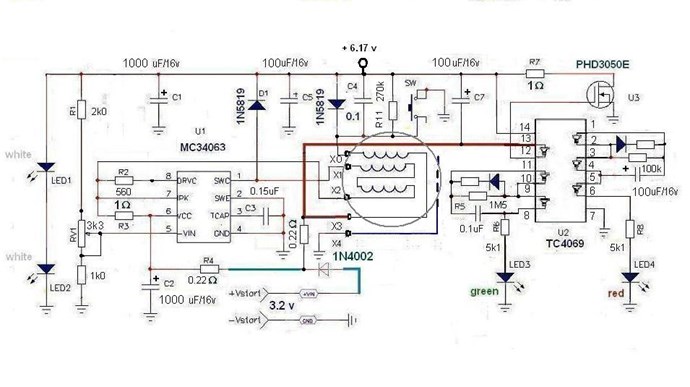
He seems to point out that the CD4069  inverter is not needed, or not important for the basic operation, at least the shaded area, the inverter connected to the external FET forms a synchronous rectifier I would guess and could be probably replaced by a shottky rectifier if the CD4069 is not employed . The resonant oscillations are driven by the MC34063 chip, which  is an analogue dc-dc converter driver. Here the internal circuit from the datasheet:

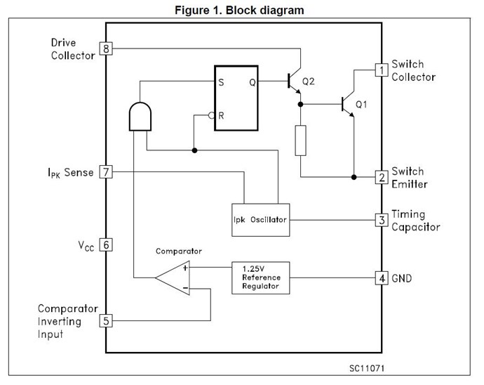
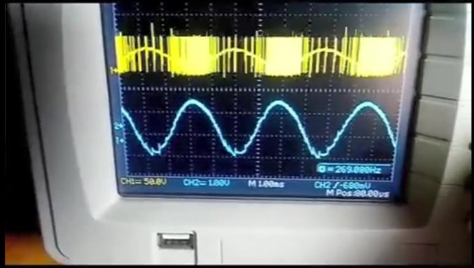
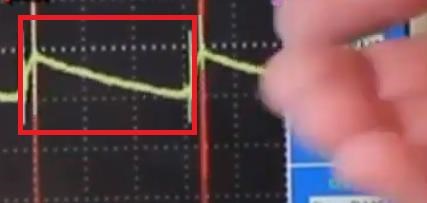
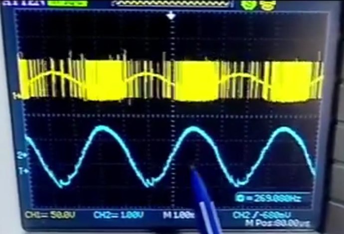
Now this reveals a very important aspect of the operation principle: note that the fundamental frequency of resonance is 269Hz (the low value indicates that the coils are bucking), but the switching frequency of the converter is set to a much higher value by the timing capacitor C  on pin 3(for 300pF it is approximately 25uS  Ton and 10uS Toff). The Inverting Comparator input on pin 5 will shut down the switching when a the threshold voltage on the output is reached. So when the output voltage downscaled by the resistor divider  on pin 5 becomes greater than the 1.25V internal reference, the driver shuts down. With this technique it can be achieved by adjusting the variable resistor , that the switching occurs predominantly at the lower halfwave of the cycle(in the case of the boost converter, where the pulses at the yellow highlighted test point are negative), which will maintain the fundamental resonant oscillation with a minimal expense of energy.

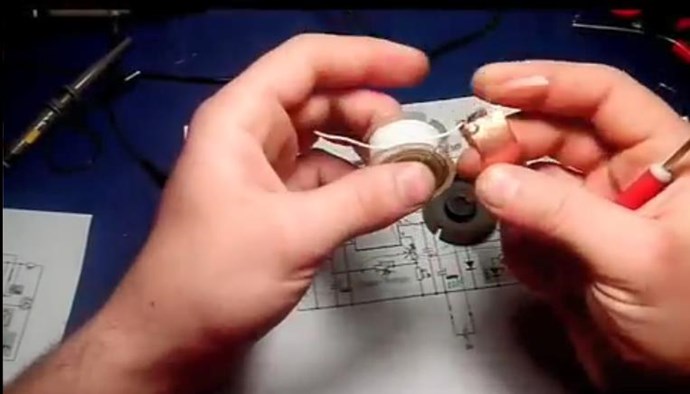
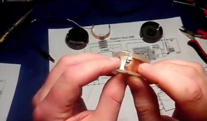
Another detail that has called my attention are the copper sheets inside of the bobbin, which are found on some other devices of Akula as well. I don't think that this is a emf shielding, more likely it forms a capacitance or capacitor in conjunction with the second sheet at the inner end of the second winding. This will of course have no effect at the fundamental oscillation of the coils at 270Hz, but referring to the switching period of the driver with a 35uS period it will have a mayor effect, and might be used in this design to achieve a capacitive coupling of the second coil.

Note that in the following screenshot the schematic sheet which is below the circuit in the video has two modifications marked:

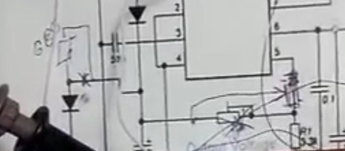
First a resistor in series with the output Led's -likely a impedance correction

Second the variable resistor for the shut down signal is changed  to a diferent configuration - for a broader range of adjustment


I think that this particular circuit would be a good start point to experiment as the basic design is quite simple. And in my opinion first the coil set have to be tuned to the fundamental resonance frequency, which is the tricky part, then the adjustment of the driver pulses and load impedance should be easier.

Order By: Standard | Newest | Votes
Jagau posted this 19 November 2020

Thank You

Jagau


  • Liked by
  • Chris
L0stf0x posted this 19 November 2020

Jagau, I am sorry bro I had no idea! I removed it already!

  • Liked by
  • Chris
L0stf0x posted this 16 November 2020

Yap! you are right Vidura! I already waiting for a new scope in following days and some other modules and so I will re-examine everything with accuracy. 

Vidura posted this 16 November 2020

Hey Lostfox, Certainly the measurement with the DMM Is not likely to be valid,Measurements of high frequency currents can be very tricky. But this doesn't mean that the observed effect does not exist. I have seen an effect in my Tesla coil experiments which could be related. It would be worthwhile to continue investigate it. Regarding the measurements, as I believe you don't have a scope, I will post an small circuit in the Measurements thread, which should be capable to condition the signal for a DMM. Not for precision measurements, but as reference for experiments. Regards Vidura.

L0stf0x posted this 16 November 2020


L0stf0x is correct, Digital multi Meters should not be used with high Frequencies, however, its not wise to dismiss effects like this on advice only!

It is worth putting a small Load Indicator in the line to see if the DMM is accurate enough! A small Globe or something, simple to check the DMM as some DMM's are very much more accurate than others and there is a very significant effect there that is repeatable with that DMM even if it is reading inaccurate Current Reading!


Chris you are Absolutely right! but this effect except that was very strange, I checked the multimeter manual and for AC current the Frequency range is :40Hz~400Hz only! So it is more than obvious that measurement was absolutely faulty. And so it has no place in the forum that's why I delete it! It was my fault! So yes! the lesson as Chris pointed is never use multimeter with high frequency laughing

L0stf0x posted this 16 November 2020

Hey Lostfox,

very interesting experiment, it certainly deserves it's own thread! May I ask if the shield is a closed loop, or interrupted in some place, this would give more clarity if a standing wave is responsible for the effect. Thank's for sharing.

Vidura.


Hey! Welcome my friend! No its not close loop for sure. I will have to try with closed loop too. On outside and inside.. Also I will try it as a short peace. We see shielding in many projects TPU, Akula's Coils, etc. But they use them as capacitor plates I think. 

The material is Aluminum I guess.. It is taken from an AC capacitor, it is one of its plates. Looks to be Aluminum. Also if you noticed the shield works when it is at the edge of the top side of the coil and as I pull it down to the middle point the current goes up again.. and when shield is all inserted again the current goes down. It sure is something to be examined because as you see the led light is stable with shield or not.

Vidura posted this 16 November 2020

Hey Lostfox,

very interesting experiment, it certainly deserves it's own thread! May I ask if the shield is a closed loop, or interrupted in some place, this would give more clarity if a standing wave is responsible for the effect. Thank's for sharing.

Vidura.

Chris posted this 16 November 2020

Hey L0stf0x,

This is great work!

L0stf0x is correct, Digital multi Meters should not be used with high Frequencies, however, its not wise to dismiss effects like this on advice only!

It is worth putting a small Load Indicator in the line to see if the DMM is accurate enough! A small Globe or something, simple to check the DMM as some DMM's are very much more accurate than others and there is a very significant effect there that is repeatable with that DMM even if it is reading inaccurate Current Reading!

A Scope and a Measurement Block would be even better.

I honestly don't think its wise to dismiss results too quickly! The one time results are dismissed that you really might have something significant. wink

Best Wishes,

    Chris

L0stf0x posted this 16 November 2020

I like to know the details please


can you add any more LEDs?


I am Sorry Forushani this was a measuring fault of multimeter! cry

  • Liked by
  • Chris
  • YoElMiCrO
L0stf0x posted this 16 November 2020

Wistiti my buddy!! Be sure I am always active My last motor/generator attempt was a failure.
My problem wasn't only the phase difference at the output (witch I correct it with output cost) but I faced also a free energy illusion but its not time to discuss it.
Just an advice to the guys that build a rotary design motor/generator. Don't think that acceleration on rotor when you load the output always means free energy.
Most of times Its an illusion! Rotor is loaded before even you power the device.. due to magnetic short circuit. Anyway.

UPDATE! To the present effect.. Probably the zero value is due to the multimeter frequency range. So False alarm probably! So I deleted the first message to avoid any misunderstanding! So about this transformer there will be update later.

I thought that maybe the effect was due to shielding. I forgot to mention that each side of transformer is covered by aluminum foil as a shield not connected to anywhere yet.

I did a fast experiment with some resonance coils I had for experiments to test the shielding.. so I record the effect for you.. have a look what a shield can do to the input current!

More to come..

Forushani posted this 16 November 2020

I like to know the details please


can you add any more LEDs?


Wistiti posted this 15 November 2020

Hi friend! For sure I'm interested to see the circuit! Thank you for being active!

Chris posted this 14 November 2020

Hello Mitza84,

Thank You so much!

Please feel free to invite others to our Forum! We welcome all Genuine Constructive Members!

Best Wishes,

   Chris

Mitza84 posted this 14 November 2020

and this is all the answer he give about this project

delamorto( vadik guk)  :      time of run      20 minutes as much as possible kept. If you watched the video carefully, then you can see how quickly everything is cut off if the circuit is not self-supporting.
Now I would have assembled it easier, at the peak, with auto-tuning .... but I don't see the point - there is no power there ..... from the word at all!
@Simple Sergey Not everything is so smooth with math, you consider the load as an LED, I consider the load to be 2 generators and 2 LEDs. The containers that are worth I speak on the video, and I say again, REPEAT AT LEAST THIS! But not in theory, but on practice 
Well, you know that Akkula fakes all his "products"
And if you remember this video, as it was the third, look for the first 2 parts, where waveforms are shown and the effect setting is described. And published because of the dispute how much you can squeeze
@FreeEman URI Stecho, the company that dealt with him said it herself, he got caught opening the device, found batteries under the windings.
@FreeEman URI all at one time on the forum was what from where and where. The video is not posted for repetition, but as an indicator that there are no megawatts in ferroresonance, there is negligible power.
@FreeEman URI I immediately said - this is the ceiling for ferrites, but in the video I said try to get it at least! Do not make plans for ferrites, this is not the source with which to resonate!
@Simple Sergey so everyone knows this, it's strange you don't communicate on the pages ?! Ask DOZOR for details yourself .....

Mitza

Mitza84 posted this 14 November 2020

circuit diagram delamorto

Mitza

Mitza84 posted this 14 November 2020

vadik posted his video 3 and look at the description of the video maybe we can convince him to join us on aboveunity it would be very good .i have him on russian facebook il try to speak with him again but i know he is very busy and he is working on metal detectors for a while i was amazed to see him posted this video he told me he lost all the videos that he had about the device because he was haked or virus something like that .   this is his account on russian facebook     https://vk.com/delamorto

the schematic for this is this one   is tricky i got the consumption down to 1-2 mA but not self running yet

Hi Chris and hello guys this is how he describe the  operation of the device from above    delamorto:    Principle of operation - ferrite cups consist of two halves, the lower half contains a coil that excites the ferrites at the magnetostriction frequency, forcing it to rattle. This results in an RF magnetic field. It is induced on the second half of the ferrite cup, which enters into resonance and also rattles, there is a feedback coil in it, with which the energy is pulsed to the main capacitor, thereby compensating for the losses. It turns out a self-sufficient generator, the load of which is a white LED, the green LED indicates loss compensation (feedback). 

Mitza

Chris posted this 03 May 2020

Hey Guys and Gals,

@AlteredUnity - I have collected many core over the years. I have many cores, many I have salvaged from old Equipment. I am sorry I cant tell you more specifically what Core I used.

The Cores are Important, in the thread: Looking for the Knee of the BH Curve

I show, deliberately, how some Cores are sort of not suitable, some have very high Saturation levels! All these experiments are worth doing to learn what is suitable and what is not! Also how we can cheat a little by adding an external source of Magnetisation, like Floyd Sweet said:

The Space-Quanta Modulated Mark 1 Static Alternator

Laboratory experiments dealing with magnetic fields support the concept that magnetic flux may be modulated by low level oscillatory means. However there is no lateral movement of flux. Rather, what happens is that the individual packets of quanta are polarized by the initiating and sustaining coherent force the field of the primary magnets or in special cases, electromagnets.

Ref: Floyd Sweet - The Space-Quanta Modulated Mark 1 Static Alternator


Soon, we will have more demonstrations on this, but if you follow what we have shown, its not hard to make those few steps ahead and get to what I have described here.

We have no limitations unless we allow ourselves be bound by what we are told, say no, do it anyway!

Best wishes,

   Chris

AlteredUnity posted this 03 May 2020

Hey Chris, what type and/or size of pot core did you use? In a lot of descriptions I see OB30 M1500, though nothing specific comes up when searched for. Thanks.

  • Liked by
  • Chris
  • Atti
Mitza84 posted this 14 January 2020

You are right Chris it seems so simple but is not i tried last night to play a little with the transformer and is not that easy as it seams and when is about resonance it leads me back to your experiment with non-inductive coil experiment wich is the basic for this type of circuits. i have two cores from china one nanocristaline and one amorphus il have to play with them to understand this basic setup of non inductive effect. thanks Chris you are always big help .

Mitza

Chris posted this 13 January 2020

Hey Mitza84,

A Circuit like this does require exceptional Timing and fiddling. It can be done, don't get me wrong, but these circuits have been designed and built by experts. They can be very fiddly.

If I may recommend, start a little more simple, replicate something that can be learned from, and then move onto the driving Circuitry. This way you will see greater progress in a shorter time.

I recommend replicating my experimental series: Chris's Non-Inductive Coil Experiment

All videos leading up to video seven, and including videos after.

Once you have the knowledge, then you can improve on it.

   Chris

Mitza84 posted this 13 January 2020

I am happy to be of help i hope someone will try this i am already trying this setup but i think il have to put a bit ticker wire. i think is to thin what i use now on my transformer.

Mitza

Chris posted this 13 January 2020

Nice find Miza84!

The Buck Boost circuit is Resonant:


Another Circuit that uses this idea is Andrey Melnichenko, specifically C5 seen here:

Pointed out in this post.


Of course in the above Circuit, the positive Terminal of C5 must be at least enough Voltage to keep the Machine Running, keeping C2 Charged, Current comes from the Magnetic Field Opposition during this part of the Cycle. Which occurs well after the Input is off as we have learned from our work!

Asymmetrical Regauging:


Evidence for these Regauge periods can be seen in the original video, spikes on the bottom of the Sine Wave:


Good spotting! Thanks for sharing!

   Chris

Mitza84 posted this 13 January 2020

Hi guys happy new year i just come across a russian scientist that is famous in russian universities and his work is known and i found 3 of his patents in witch he claims over unity and they look really simple if you read the patents you would understand very easy what is all about and i think is related to the sistem here  il post the links and you will see the schematics  . 

https://patents.google.com/patent/RU2600097C1/en

https://patents.google.com/patent/RU120830U1/en?inventor=%D0%93%D0%B5%D0%BE%D0%B4%D0%B8%D0%BC+%D0%A2%D1%80%D0%BE%D1%84%D0%B8%D0%BC%D0%BE%D0%B2%D0%B8%D1%87+%D0%9A%D0%B0%D1%81%D1%8C%D1%8F%D0%BD%D0%BE%D0%B2

https://patents.google.com/patent/RU76515U1/en?inventor=%D0%93%D0%B5%D0%BE%D0%B4%D0%B8%D0%BC+%D0%A2%D1%80%D0%BE%D1%84%D0%B8%D0%BC%D0%BE%D0%B2%D0%B8%D1%87+%D0%9A%D0%B0%D1%81%D1%8C%D1%8F%D0%BD%D0%BE%D0%B2

Mitza

  • Liked by
  • Chris
  • Jagau
Mitza84 posted this 30 October 2019

HI raviope if you look at the pdf i posted above  you will see that you have LC resonance in delamorto circuit secondary coil is in paralel with a capacitor to create resonance and the bigest amplitude and then the energy is returned back to the source capacitor trought a transistor . anyway good point there well have to experiment to see how it goes . for the moment il move back home and i can experiment again after 1 november so il keep you guys updated when i start again with the experiments   i go in paralel with delamorto and melnicenko circuit from Chris and see wich perform beter. or wich i can manage to make it work .

Mitza

raivope posted this 23 October 2019

Hi all!

Interesting topic!

To my knowledge - there are many different working principles, better to differentiate:

  1. high frequency, fast switching, CEMF (cold) pulses, which do work in battery (or capacitor). They cannot be looped directly. (Bedini, Don Smith, Bearden)
  2. low frequency FR (ferro-resonant) systems that work well at 50-60hz, based on saturation asymmetry (1+1 < 2) or especially taking advantage of non-linearity and the environmentally open thermodynamics of ferro-magnetism (parametric change).
  3. other

If we look closer to the pulsing system - we invest energy and we collect energy (CEMF). When we can hack into permeability during those cycles - we can get more from the environment. E = .5 x L x I^2 (where we change L). In ferromagnetic systems L always is dynamic. When we pulse transformer differently we might have different average L.

When you oppose coils (same as in Akula's circuit that charges capacitor in normal transformer fashion during invest cycle) - we create opposing fields that direct the flux outside of the core where permeability is forced lower.

When we collect CEMF - we have very constructive flux in primary and secondary halves where permeability is increased.

So - everything comes to the transformer design - if you wire all coils on the same leg over each other - you won't have success in CEMF (collapsing EMF) system. (Ok - Akula's one design may be exception when he uses invest cycle to diminish the permeability, which single leg design permits).

Interesting - why Akula uses copper sheets? Maybe it will make coil more stable to environment capacitance - i.e. when you move your hand nearby, it will not destroy the resonance.

So - further - those were pulsed systems, but why not to use AC system where you have LC resonances in secondary (or middle) of the circuit that does all the stuff without much worry about switching. Only designing proper transformer with coils at right positions. LC resonance can act on a coil same manner as you are doing this coil oppositions, and in resonance it pulses in a proper phase. If things are more understood, I guess it can be designed to send more energy back into the "grid" as a reactive power. You need a power meter (or proper scope) to see the direction.

So, my point was to simplify - maybe its just the permeability hack as a principle?

Mitza84 posted this 22 October 2019

Thanks Vidura any theory is recived well i hope we see the end of this device . when i made the device i take steps first i make the oscillator part and then after is working ok i made the returning side of the device what i notice at this device is when i connect the second part with some coil  the frequency is geting higher   oscilloscope on pin 1 and the ground . because without the second part the device go on very low frecuency because of the 0.15uF (150nF)  somewhere in hundreds of hertz . (  Capacitor wich give the frequency of the oscillator on pin 3 of the mc34063,)  So just the oscilator side leds light frequency low and consumption about 10-15mA  , with the returning side leds go off and frequency higher. and amp draw  go crazy .

Mitza

Chris posted this 22 October 2019

I hope that Chris will not bann me for posting to much theorylaughing.


No, absolutely no way that I would do that Vidura.

I only Ban Trouble makers, Trolls, those that are here to distract, attack, to be-little others, you're not going to get Banned for trying to understand the Technology.

I value everyone here, and I consider you all part of my family, extended family. Like I have said, we are all here making History!

Best Wishes

   Chris

Fighter posted this 22 October 2019

Your post is precisely on subject and it's trying to explain the way a device work. So no worries Vidura, nobody is banned here for this kind of "theory" laughing

Vidura posted this 22 October 2019

Hi Mitza84.

Although I have not managed to make this device work( I have not spent too much time I must say), I will give you my point of view how it would be in theory, taking in account the latest results of investigation. The secret is in the coil, when it is in magnetic resonance a high potential will appear as an E-field, and will be captured by the grounded metal sheet. at the same time a negative pulse will be inverted by the Schmitt trigger and open the switch, which acts as synchronous rectifier and will loop the energy from the captured E-field to the positive rail.  This is only hypothetical for the moment, I hope that Chris will not bann me for posting to much theorylaughing.

Vidura

Mitza84 posted this 22 October 2019

Hi guys i made the schematic that Chris posted and i am having a little trouble when i connect the tc4069 part everything is turning of is like i make a short circuit on the device , i dont know what is wrong and the consumption go very very high.  if i conect just the oscillator side with the first coil everything is fine leds light well no trouble ,  i use a irf3025 mosfet  i still dont get how the part with tc4069 should return the power back .  maybe i can get some advice? 

Mitza

Attached Files

Jlezana posted this 22 October 2019

Thanks Friends ... the New Thread is over here:

http://www.aboveunity.com/thread/modified-armstrong-oscillator-por-jorge-lezana/

I hope you like it and serve your experiments.


Regards
J.Lezana


YoElMiCrO posted this 22 October 2019

Como todos también te doy la bienvenida.
Este foro es una comunidad muy unida y respetuosa.
Mientras mas seamos mejor.
Desde ya gracias.


YoElMiCrO

Jlezana posted this 22 October 2019

Thank you very much friends for the welcome, give me a little time and I will create a separate thread ... with the details, have a little patience, I will try to do it in English Translated so that you understand it.

I want them to be able to replicate it and share experiences about it.

Effectively work with the lasersaber scheme, the problem is that he does not give details of where this circuit comes from, it is difficult to adjust and does not always work ... and worse still, when it does, it consumes a lot of current, about 3 or 5 milliamper . My replica is working in only 60uA.

I will give you more information on where the base scheme comes from, and more practical and technical details that I hope will help you in your replicas.

I do not want to dirty this thread with this project, because I have also assembled the Akula circuit and I have several doubts that I would like to help me understand.

My first help I need is:
Will someone be able to switch to text in English, the photos posted by the Admin (Chris posted this 04 September 2018 - Last edited 04 September 2018)
So I could translate and read them in my language and try to understand more.

I appreciate the help.


While I will be writing a little bit the New Thread I will call: Modified Armstrong Oscillator (OSC_ARM_MOD_JL01)

Regards
J.Lezana

fer123 posted this 21 October 2019

Hola Jorge bienvenido al equipo de investigacion, esperamos que te sientas comodo y puedas desarrollarte al maximo. Saludos.

Vidura posted this 21 October 2019

Hola Jorge y bienvenidos al foro, Muy bueno que haya mas miembros activos en el continente sudamericano, estoy curioso sobre detalles de tu circuito, gracias por compartir. Vidura.

Chris posted this 21 October 2019

@Jorge - Welcome!

Nice work! I left a message on your Channel, well done!

I agree with Fighter, I would like to give you your own thread, as your work does deserve it! Is this device something you want to further, to keep working on? If so I can help you with creating your own Thread if you wish?

Anyway, well done!

@Mitz - Like anything in life, learning to perfect something takes time. We can help, we all can help, but we must put the effort in to get there.

I will protect everyone here from Trolls, no one here gets trolled / Bullied by the non-believers. So please feel free to join, share, to add your bit.

   Chris

Fighter posted this 21 October 2019

@Mitza84, "seem to be" means we don't know if it's using Akula's principle or not until he is presenting his device, right ? The coil of the device looks a lot like Akula's coil and he's specifying it's "a very similar but simpler device".

@Jlezana, I encourage you to create a thread for presenting your device, I'm sure we all can learn from the details of your device, I find it very interesting.

Mitza84 posted this 21 October 2019

Hi Jorge your device seem to be like  lasersaber sjr looper circuit i played with them alot they seem to be the only circuits that eat much less power for the returning light you get on leds,  and trust me they dont work at all like this lantern. but they are very echonomical flashlights indeed ., Welcome and hope we get good results soon .     

Hello Jagau thank you for wellcoming me .   i have also one schmeatic with a modification i tryed and eat less power than the original design of Vadik guk.    ill atach the photo down , next il try  the schematic  that Chris used , maybe works beter than this.  

Mitza

Attached Files

  • Liked by
  • Chris
  • Augenblick
Fighter posted this 21 October 2019

Hi Jorge,

Your device is very interesting, nice work !

I think your device deserves its own thread, if you want to create it and present your device and details feel free to do it, personally I'm looking forward to read your thread.

Regards,

Fighter

Jlezana posted this 21 October 2019

Hello Friends ... thanks for sharing this forum, I am from Chile and I write in Spanish, I use google translator, to send you my notes.

Years ago I built the Akula circuit, and I had no promising results ... today I have trouble analyzing it again ... I have manufactured several transformers and adjusted the frequency, but it does not work more than 2 seconds with a 1000uF capacitor at the entrance, I have some equipment to measure, so now with your information I could go more calmly understanding this device ..

The current consumption of this circuit is around 4000 MicroAmperes, which is quite high.
I don't know if someone has measured the consumption current of their replicas?

In parallel, I made a very similar but simpler device that I would like to share with you and I think it works in the same way as the akula circuit.

I leave the sample video:

Thank you for sharing all this information that is really helpful in this device.
If you think this device requires a new forum, just let me know and I create a new post with the details of it.


Atte.
Jorge Lezana

Jagau posted this 21 October 2019

Hi Mitza84

this little lamp is a real challenge of energy management.

youy are welcome

Jagau 


Mitza84 posted this 20 October 2019

Thanks alot Chris i was thinking that this is the right one you used , Vadik used the one with the transistor posted in my pdf ,il put a photo also of the one he used it but if you get some minutes of work without battery or power supply that mean is easier to get it to work so we are on the right track with this schematic . his is more tricky and harder to get it working. so il try to make this one for now i hope il get it working with your help guys . thanks alot again Chris for the infos.

Mitza

Attached Files

Chris posted this 20 October 2019

Hi Mitza84,

Vadik Guk showed a working machine, as have others using the same Circuit:

Of course a few minor modifications will be required depending on your coils. A 180 ohm resistor on Pin 8, but with work and study of others work, this will be easy to find.

I cant remember the turns, but again work and study will give you a figure that is good.

   Chris

Mitza84 posted this 20 October 2019

i want to know wich schematic did you use that time and maybe if you can ,how many winds on the coils? ,if you get minutes of work from the capacitors that,s  a big deal, i want to know more , i will be pacient with this and il work on it until i see it work ,

and the link that vadik guk gave me this is very recent ,for those interested and might be of help is this is it 

https://strannik-2.ru/index.php/forum/t-kapanazde/473-prostye-skhemy-s-zazemleniem#44918

Thank you Chris i wait for your answer.


Mitza

  • Liked by
  • Fighter
  • Augenblick
Chris posted this 19 October 2019

Hey Mitza84,

You wont get banned for posting a single link. wink

I had that machine, after many hours of tuning and fiddling, running for several minutes at a time with no input. I cant remember the consumption, but the capacitors held the machine in self sustaining mode for quite sometime.

Some advice if I may? Be patient, learn as much as you can, build, experiment, document your work, and share with us as much as you can - We will do the same!

Together, we can all progress!

Everyone is safe here!

   Chris

Mitza84 posted this 19 October 2019

i saw your replication what was your consumtion do you remember ? i used one led exacly like vadik use in the 4 videos that you posted before , and i get very good brightness under 5 mA  but the problem is to make it self sustain thats my goul . the think is when i ad the other part of the circuit with the cd4069 and the transistor ( the return of energy ) the circuit it start to take much more energy and here i got stuck.

Mitza

Mitza84 posted this 19 October 2019

Hi Chris thank you for  wellcomeing me  i followed your work for a long time but i did not get my toughts online  before i make a working replication i saw also cd-sharp and vidura and the others that post good work ,i think you Chris put very precious information and i want to come with a little help to make one good replication that works , but till now i did not succed i was checking also russian forums for infos and try to get in touch with the russian guys and i spoke with Ruslan Kulabuhov and Vadik Guk ,Ruslan was a little secretous he gave me the impression that he want to help but he did not say to much he tell me even if i have a good schematic i will not be able to tune it right so is usless for me to try ,he sad that is an atomic process happening in the core and the ferrite will shatter eventualy , so will get destroid from vibration after a while so is not forever , Vadik guk try to put me on a good track ,he sad not to louse my time with this lantern cose will be very dificult to make it work and to try to work with the katcher and grounding because he had very good results with these  he gave a a forum where they put updates if you are interested to know i will post the link because i do not want to get baned for promoting other forums . 


Mitza

Chris posted this 19 October 2019

Hi Mitza,

Welcome! Thanks for participating! I did a replication:


Yes it is true, one can spend many hours replicating these machines. Patience and study will see success. Stick at it.

   Chris

Mitza84 posted this 19 October 2019

My replication of the circuit is as follows i get it under 5 mA of consumtion the part of oscilation and the returning key is consuming a mbit much with the original design so i try to find oscillators that eat less energy so insted of that cd4069 you can use a ts555 with a simple schematic to trigger the transistor that return the energy.

Mitza

Attached Files

Mitza84 posted this 19 October 2019

read very carefully the pdf he first write in russian and than is the eng translation . i hope that helps the conversation go trought all stages that it takes and the 4 videos from vadik guk that are posted here are related to this pdf he did them while chating on the forum with avalon.

Mitza

We're Light Years Ahead!
Members Online:
What is a Scalar:

In physics, scalars are physical quantities that are unaffected by changes to a vector space basis. Scalars are often accompanied by units of measurement, as in "10 cm". Examples of scalar quantities are mass, distance, charge, volume, time, speed, and the magnitude of physical vectors in general.

You need to forget the Non-Sense that some spout with out knowing the actual Definition of the word Scalar! Some people talk absolute Bull Sh*t!

The pressure P in the formula P = pgh, pgh is a scalar that tells you the amount of this squashing force per unit area in a fluid.

A Scalar, having both direction and magnitude, can be anything! The Magnetic Field, a Charge moving, yet some Numb Nuts think it means Magic Science!

Message from God:

Hello my children. This is Yahweh, the one true Lord. You have found creation's secret. Now share it peacefully with the world.

Ref: Message from God written inside the Human Genome

God be in my head, and in my thinking.

God be in my eyes, and in my looking.

God be in my mouth, and in my speaking.

Oh, God be in my heart, and in my understanding.

Your Support:

More than anything else, your contributions to this forum are most important! We are trying to actively get all visitors involved, but we do only have a few main contributors, which are very much appreciated! If you would like to see more pages with more detailed experiments and answers, perhaps a contribution of another type maybe possible:

PayPal De-Platformed me!

They REFUSE to tell me why!

We now use Wise!

Donate
Use E-Mail: Chris at aboveunity.com

The content I am sharing is not only unique, but is changing the world as we know it! Please Support Us!

Thank You So Much!

Weeks High Earners:
The great Nikola Tesla:

Ere many generations pass, our machinery will be driven by a power obtainable at any point of the universe. This idea is not novel. Men have been led to it long ago by instinct or reason. It has been expressed in many ways, and in many places, in the history of old and new. We find it in the delightful myth of Antheus, who drives power from the earth; we find it among the subtle speculations of one of your splendid mathematicians, and in many hints and statements of thinkers of the present time. Throughout space there is energy. Is this energy static or kinetic? If static, our hopes are in vain; if kinetic - and this we know it is for certain - then it is a mere question of time when men will succeed in attaching their machinery to the very wheelwork of nature.

Experiments With Alternate Currents Of High Potential And High Frequency (February 1892).

Close