Atti's Adams Motor Replication

  • 1.7K Views
  • Last Post 09 August 2020
Atti posted this 14 May 2020


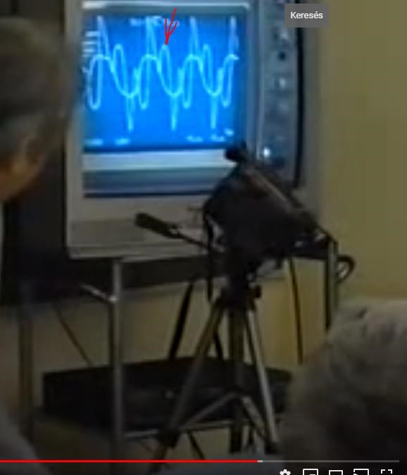
This is an older recording. I don’t know if anyone else has done similar measurements and since there is no separate thread I put it here. He doesn't cut here tightly. (If you think you don’t need to be here or bothered by this post then feel free to delete it!) But because I think some parts of the oscilloscope figure are thought-provoking. After all, the frequency corresponds to the speed and the filling can be adjusted in the same way.
I think the operation in the Adams motor and the ZPM or non-inductive coil system are somewhat similar in operation.
 Here it is a fully open magnetic system, while it is closed in a transformer. Except with the proper air gap.
Effect of excitation voltage (or current) on the load. As well as the effect of the magnetic field coked by the load on the excitation. They appear on top of each other. For example, at the 5th minute. True, because of the quality of the material, there is no such spring-like oscillation here. But, for example, the slow decay resulting from self-induction voltage (and current) is clearly visible in a trapezoidal or sawtooth wave. At 7:10. This and the combination of the input pulse exercise the ascending speed in the ideal angular position.
I will continue from here.

Nagy Attila.

Order By: Standard | Newest | Votes
Atti posted this 09 August 2020

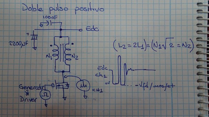
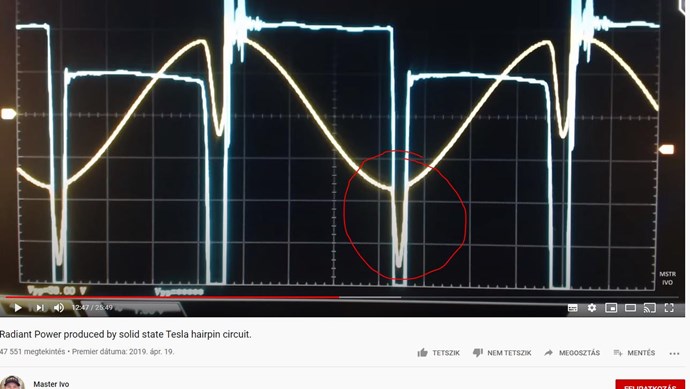
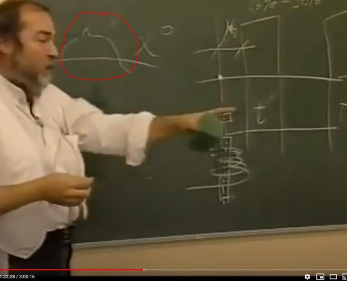
I also saw this double positive impulse once. Voltage and non-current shape. Unfortunately, I did not document it. At the top of the heap (cube or sine does not matter at all), another heap appears. Totally on top. "Cici" effect. (like a female nipple) This occurs when two identical magnetic fields meet or resonate. I also saw it in Chris’s asymmetric system.
It doesn't just occur with the Adams engine.

YoElMiCrO circuit is similar. You need to see the double positive impulse.


-2: 01: 40 


It starts at 3:50, but can also be seen in Akula’s circuit.


-It was also felt in the parametric system. This is just a quick test.This is an older save. At the beginning of the video, the drawing says it all. You don't have to pay attention to speech.

think we need to look for such and similar phenomena. Profits always occur then.

Atti.

Chris posted this 13 July 2020

Hi Hermesatar,

Welcome!

We cover a lot of information in the thread: Non-Linear Inductance

Inductance is a difficult quantity to formalise, as the equations change depending on the geometry of the Coil, from single layer, to multi layer and so on. The basic formula is: L = V / ( I / t ) or L = Φ / I

Regarding your questions:

If you double the turns of an electromagnet. Does the inductance doubles also?


An experiment will give you a close approximation, experiment is one of the best methods to learn:

Ref: http://tesla-institute.com/%21app/sim/acic.php


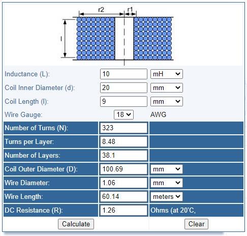
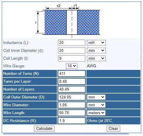
Comparing the figures obtained, the answer would have to be no. The turns 323 compared to 411 = 1.272 more. Remember, this is a simple experiment using one formulation, there are different formulations depending on Coil Geometry, this will change the answer.


do you think it is possible to build a solid state version, like the Clemente Figuera device?


Yes, but only when one understands the basic requirements of Energy "Generation". Until this point, if one does not understand the basics of Energy "Generation", then one is guessing and therefore will have to be extremely lucky to make any progress and even if progress is made, then one will not understand why results were obtained and will very likely not be able to replicate the results easily!

Closely studing the words used by Figures, he hints to exactly the same thing I just said:

Watching closely what happens in a Dynamo in motion, is that the turns of the induced circuit approaches and moves away from the magnetic centers of the inductor...


Of course, the patent and writings are hard to understand, but observing the basics and following Facts and useful known to be good information, will be of great benefit!

On this forum, you will find working Machines, doing exactly what you are looking for, if you observe and take notice of the main experiments marked as Above-Unity then you will gain this knowledge.

Figurea was over 100 Years ago! It is time we Humans step up and be what we were supposed to be: Free and Independent!

Best wishes, stay safe and well,

   Chris

hermesatar posted this 13 July 2020

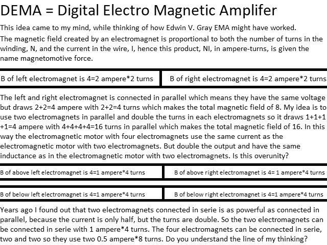
I have a motor question. If you double the turns of an electromagnet. Does the inductance doubles also? or does the inductance increase four times?

http://gratisenergi.se/dema.jpg

Best Wishes, Hermes

P.S do you think it is possible to build a solid state version, like the Clemente Figuera device?

http://gratisenergi.se/figuera.htm


L0stf0x posted this 03 June 2020

Nagy, I agree, more phases doesn't mean faster rotor, rather the opposite. My motor will be very different..  A second "new type of multiphasing" will be installed, that will work in harmony with the existing 3 phasing... It is not a known setup, I have not seen it somewhere to give you a link, it is a completely new idea and I am not sure it will work the way I am thinking about it. Maybe it will fail.. we will see soon! smile


Chris posted this 02 June 2020

Hey Atti,

The Jack-Hammer is a Good Analogy!

Action, the Pneumatic Actuator causes an Action, this translates to the Chisel, the hitting the Concrete creates a Reaction, this translates back up the Chisel, then the Pneumatic Actuator again sees a Counter-Reaction.

If this was timed correctly, the Counter-Reaction could Assist the Action, thus the Pneumatic Actuator could be Assisted by this Force, assisting in the Chiseling, requiring less work from the Pneumatic Actuator.

Best wishes, stay safe and well,

   Chris

Atti posted this 02 June 2020

Hey L0stf0x.

It was a similar layout to what you just wrote to us. So it is multi-phase. Although I only examined it in two phases at the time.
The study covered whether there is a speed increase in two (or more) phases.
(I think that if there is an increase in speed, the motor will not slow down to such an extent that the shaft is loaded. This voltage can be connected to the supply voltage of another coil. Teuro Kawai's arrangement is similar, Árpád Bóday's M.D.G. transformer charging is similar.)

   A poor quality image of a two-phase drive. I've done this before. 


(I wanted to do a test for a multi-phase layout. Unfortunately, the machine cutter damaged the rotor. So I stopped this idea for now.) Pictures: 

Same result, but at the right angular position, the acceleration of the motor under load is even more noticeable. No separate generator coil was installed during the test.
The load is either removed from the foot of the FET drain or placed on a separate coil. But it's already a waste of material. But it also has its advantages. (If we think about it, it's an open-core transformer.) But the point is the same as what you wrote.
However, both poles of the electromagnet were used in this arrangement as well. Much like what you see in the second half of the video. 

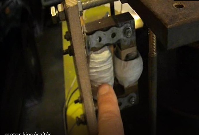
This picture shows that there is an iron core with an air gap.

On the left is the excitation coil and at the top is a secondary coil. The right roll is a separate roll. If this right coil is loaded, it will only slow down the rotation of the rotor.
Thus, the magnetic effect of the secondary current does not contribute to the excitation. (oscilloscope diagram examinations)
(compare this arrangement with Chris's asymmetric transformer. Replace the coils. L-1-2-3.)


Lately (and well for a while) my playmates can be seen here. My favorite is the middle green monster.

  For now.


Nagy Attila.

Atti posted this 02 June 2020

raivope


Having resonance capacitor on stator may be useful to transform cold CEMF to usable.

What do you think about how it could be used. In what form in what implementation. Maybe you have some experience about it that you can share with us?
Thanks.Atti.

L0stf0x posted this 01 June 2020

Thank you Atti, As is now, its just 3 Adams motors in one, with stators and magnets, arranged to form the well known three phase timing. That is all at the moment. By using 3 phasing you get continues torque because the magnets are helping each other.. The time that the one phase sense repulsion, the next phase at the same time  attract the next core.

The Interesting part is not implemented yet...


Atti posted this 31 May 2020

L0stf0x, You have put a lot of work into this engine implementation. Congratulations on your implementation, your efforts.

raivope

 Having resonance capacitor on stator may be useful to transform cold CEMF to usable.

I have noticed that this does not bring good results. At least in the setting I used.

Atti.


L0stf0x posted this 31 May 2020

Thank you Raicope,

I think bearings are made of hard steel and the star is quality Inox, fully paramagnetic. 

Be sure I will test all of these and other things! 


raivope posted this 30 May 2020

Hi,

Nice setup! Spark features are especially interesting. It may give gains, especially when you have different metals combinations where spark is occurs.

Also, you can try what happens when you use bias magnet on the other side of drive coil. Try both polarities.

Having resonance capacitor on stator may be useful to transform cold CEMF to usable.

L0stf0x posted this 30 May 2020

Update: I quit mosfet switching because I needed the coils to be open before the magnet approaches..

so I made a star commutator and bearings (to not destroy and make groove on resin) to do the contact instead of brushes, Its a bit noisy because I couldn't make the star so leveled, and sparking is also a problem, but I bypassed other important problems!

The motor now is powered only at 13% (i am sure I can get it to <10) per complete revolution instead of 25% that has a successful Adams motor!  

more to come soon!


Atti posted this 17 May 2020

 It still need work and time to finish it..

Lostfox

Just keep calm. Family and work are a priority for everyone. Only then can the "hobby" come.
Right now, I can’t do anything else just read, no construction. I can only read the forum for weeks now.But regardless. Maybe others will feel like building and getting involved.
Be calm and safe. All my respect.

Atti.

L0stf0x posted this 17 May 2020

Dear Atti, Be sure, I will post it when its ok and running..  the motor timing is too complicated to draw it. I still work on it after all... It would be better if I post it completed and working with a detailed video.

I can describe it a bit ... The motor is 60cm x 60cm x 15cm height, it is big because I had the large (very strong) magnets from past experiment and also I started making this motor to use it in a gravity project (I wanted good solid torque with minimum input power). So the Adams motor design came immediately to my mind. But lately, I change alot the design to give more torque with much less power. So right now I reform it according to the new design..

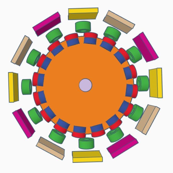
The motor now accommodates 28 neodymium magnets and 36 coils, one rotor and 12 magnetically insulated stators. 16 magnets with 12 coils do the one set of phase switching, the rest of magnets and coils form a different set of phase switching.

Both phase switching sets work completely independently.

Both work spending only the power needed for the one set to run.

Both sets auto synchronize in a way that help each other so power needed for the motor to run will be much less than usual.

With few words ... The combining of the the 2 phase sets does that.... While the magnet approaches the core, the core instead of being a neutral iron core, it appears to have opposite pole (without spending power!) and that attraction speeds up the approach of the magnet, then when the magnet is at position where the drive coil need to pulse, the same time the core appears to have the same pole facing the magnet (independently from the drive coil) (also without spending power!), so the repulsion force gets bigger...

so bigger attraction on time, bigger repulsion on time, and less power to do the job.

Right now I am remaking it. It still need work and time to finish it.. 

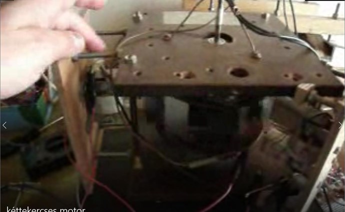
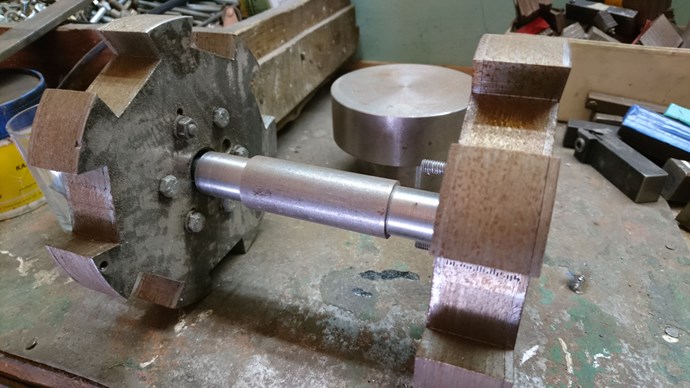
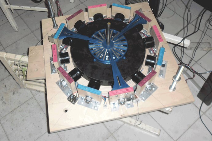
This is just a photo that I had (before about a month) of the older version (3 phase Adams motor is open). I did good tests it at ~200VDC. 

Offcourse the design will be different now... The plan is to get around ~200 Newtons torque at the shaft, by using ~400VDC or more, with near zero current. I hope


Atti posted this 15 May 2020

Hi.

Thank you all for the detailed and exhaustive answers. You are really nice.
I didn't mean this post here (Chris did it here) but maybe it's better that way. There really is no separate thread for engines. I have to say I'm not an engine expert either. I can only say my opinion and experience.

This person has met the work of Robert Adams several times. Personally.

It is clearly talking about excess heat energy. Of course, it also has side effects. For example, the speed increase shown. (In the case of a transformer driven by a self-closing oscillator and loaded with asymmetrical coils (POC), the phenomenon is similar. The frequency decreases or increases at the same load!)
Or more of the strength of the filled current.

This machine also takes out the excess energy in the form of heat energy.
Machine with asymmetric pole. And this is a great performance!

Heat energy is also discussed in this post. (but that may be just theory) Smudge's papers.

https://www.overunityresearch.com/index.php?topic=3862.msg81752#msg81752

I think the excess torque is best returned by this machine.

built an Adams engine in a similar version, but in a different design! Not feeding different coils at the same time! Restoring the self-inductive voltage does not cost your own system. After all, it’s like a coupled reluctance motor but with a different magnetic circuit. As the result of the measurement was uncertain I did not deal with it in more detail. I will be plotting the measurement on another more precisely built engine.
Similar energy recharge theory here and here: http://jlnlabs.online.fr/projects/ipstst/html/ipstst11.htm

Lostfox. I'd be really happy for you to send me a drawing of it sometime (when your free time allows). Thanks in advance.

So I think the phenomena observed in different machines can always be found somewhere. So these little results need to be kept in mind but we need to think about the rest as well.
Furthermore, I also think that a machine that can be used in a household cannot work insecurely. The process of their operation cannot be based on just one parameter. For example, resonance. Because if my resonance is such that if I reach in and change, it’s not worth anything at all. (in ferroresonance state, multi-controlled reactive power 3-5 .Not stable) The transformer has a simpler design, but the motor is more observable.


I know these are incredible ambitious plans. But there is a lot to keep in mind.After all, it's just a hobby. :-)

Nagy Attila.

raivope posted this 14 May 2020

Hi,

I am not an expert too, but I have visited a great inventor in Australia who have met and learned things from Adams himself. Adams was already quite old then he learned from him. So when later on I visited my inventor, I jokingly told that I am now part of "Adams family"

I try to gather what I remember: Adams used transistors - switching both rails at once. My friend (inventor) used went to mosfets and gained more efficiency. Key is to pulse both sides at once, so you have to drive mosfets correctly. (all the internet is full of single mosfet/transistor crap as he told) Drive them at 20V at least and dump to zero as fast as possible. The CEMF you have to direct further from source! If you do not do this you will fail, because its type of cold electricity. Direct looping will fail. You have dipole balance when you double-rail switch it. You release it symmetrically, leaving all contacts from the source off. Now - he used to have double diodes (symmetricaly) to send CEMF to a capacitor or load or other motor or the same motor other coil. But not back to the source.

Next - you have to load the motor to get CEMF. It will not run on peanuts as he used to say. Invest to get out energy. Do not use aluminum frames or you lose efficiency. Use proper cores (Somalloy, etc)

Now, follows my interpretation:

If you pulse a coil at (or slightly before) TDC you have lower relative permeability. If magnet goes further, permeability increases. This might be the reason for the gain. E = .5 * L * I^2 (L is increasing). I may be wrong, but I still stick to this.

(Adams is similar to opposing coils (POC) too where you imagine magnet being the opposing coil.)

OK, what else happens when you have asymmetry in permeability and you pump ether? Then electron "spin" is different and is cold. What can it do? It can do work. But the best it can do is to split the water - that is it can charge the other battery. So this goes to Bedini principle that Bedini (or Adams) motor is nothing more than a switch to create special effect in a battery.

And yes, Adams with mosfets resulted in real work gains, but you have to have circuit that transforms cold into hot or uses it on load or smart way switches to other motor phases.

R


L0stf0x posted this 14 May 2020

Hello Atti, very very nice testing you did there! Keep it up! I am happy because I don't see many people here experimenting with motors. 

I don't consider my self an expert, not even close to that.. But I will tell you few things that I believe can help you or anyone that is building an Adams motor .. 

I have tested Adams motor and my opinion is that is the most efficient motor out there. No question on that.

The Adams motor can give well overunity results, but honestly and maybe I am wrong but I don't think that this is the correct way. I mean to get more electrical power directly from the motor.

Have in mind that most Adams motor drawings that you can find in internet are well tested by many experienced people all these years. Yet none has the remarkable results as far as I know offcourse. 

Adams named his discovery as a motor, not as motor/generator, nor as generator. It suppose to give excessive torque not excessive electrical power. I think It is much easier to get a better torque from this motor by altering its design.

Trying to get to free energy, we need to trigger Ether directly through the system that we build. Symmetry is a neutral state. I guess symmetry is our enemy here. Offcourse a motor become instantly asymmetric when different coils are powered, but this asymmetry is not the asymmetry I am talking about, this asymmetry is always costing additional energy to achieve it.

 My opinion is that Asymmetric systems is the key to every free energy device. Real Asymmetry that can trigger ether directly in a motor is not easy to even imagine it. All motors rely on mechanical symmetry and electrical asymmetry.

I happen to build a pulse motor (something like Adams motor, but quite different) right now. I designed it to give continued excessive torque with minimal power at input. So then I can connect a dynamo to translate this torque to electrical power.

After several months of failures trying to make a real asymmetric pulse motor, finally I came up with a new design of a pulse motor. Its asymmetry rely on the combination of two different type of phasing (sets) switching methods working together without the need of extra power.

At the moment is very difficult for me to explain more details as you need to see it, to understand it. It is very difficult for me to make a drawing with the switching timings of the two phasing sets.. I hope I will complete it soon and post it.

Try something new based on the kind of system you build. Try to think of something that is not tested yet. Simulate it in your mind first, if its ok, make it.  If still it doesn't work the way you want, think a better way. If it still doesn't work, don't get disappointed, never get disappointed. The solution is hiding in your head. You are wise... you can do it! And this is going to all setups here. Do it your way!! We all have the power to do it.

I hope my words helped you.

Keep up the testing!


Jagau posted this 14 May 2020

Hi atti
Excellent demo Atti
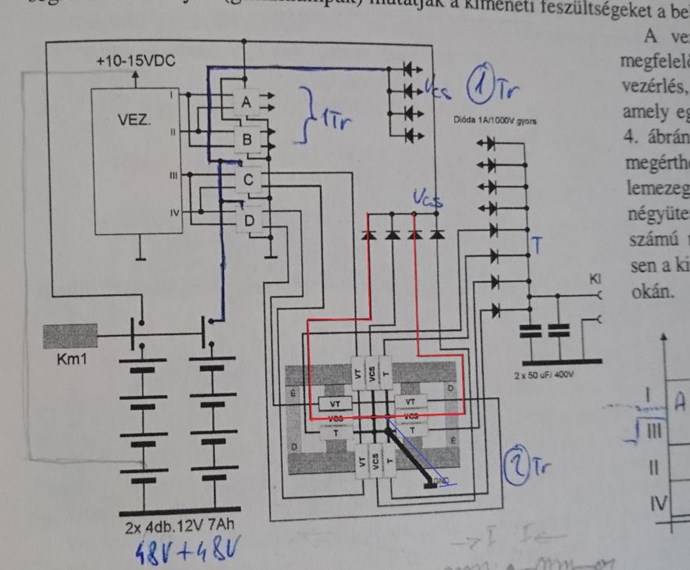
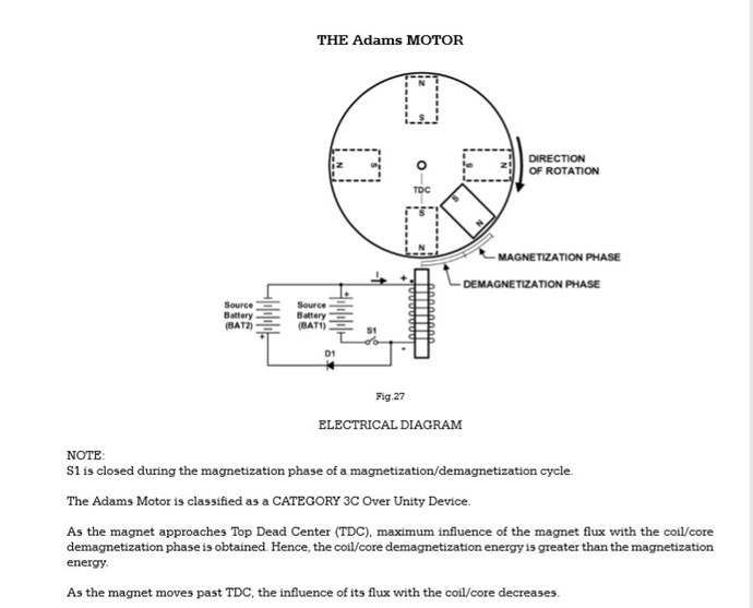
Bill Alek ing. considered the Adams motor to be aboveunity device
here is a picture he had published in his book and a very good explanation

thanks for sharing
Jagau

We're Light Years Ahead!
Members Online:

No one online at the moment


What is a Scalar:

In physics, scalars are physical quantities that are unaffected by changes to a vector space basis. Scalars are often accompanied by units of measurement, as in "10 cm". Examples of scalar quantities are mass, distance, charge, volume, time, speed, and the magnitude of physical vectors in general.

You need to forget the Non-Sense that some spout with out knowing the actual Definition of the word Scalar! Some people talk absolute Bull Sh*t!

The pressure P in the formula P = pgh, pgh is a scalar that tells you the amount of this squashing force per unit area in a fluid.

A Scalar, having both direction and magnitude, can be anything! The Magnetic Field, a Charge moving, yet some Numb Nuts think it means Magic Science!

Message from God:

Hello my children. This is Yahweh, the one true Lord. You have found creation's secret. Now share it peacefully with the world.

Ref: Message from God written inside the Human Genome

God be in my head, and in my thinking.

God be in my eyes, and in my looking.

God be in my mouth, and in my speaking.

Oh, God be in my heart, and in my understanding.

Your Support:

More than anything else, your contributions to this forum are most important! We are trying to actively get all visitors involved, but we do only have a few main contributors, which are very much appreciated! If you would like to see more pages with more detailed experiments and answers, perhaps a contribution of another type maybe possible:

PayPal De-Platformed me!

They REFUSE to tell me why!

We now use Wise!

Donate
Use E-Mail: Chris at aboveunity.com

The content I am sharing is not only unique, but is changing the world as we know it! Please Support Us!

Thank You So Much!

Weeks High Earners:
The great Nikola Tesla:

Ere many generations pass, our machinery will be driven by a power obtainable at any point of the universe. This idea is not novel. Men have been led to it long ago by instinct or reason. It has been expressed in many ways, and in many places, in the history of old and new. We find it in the delightful myth of Antheus, who drives power from the earth; we find it among the subtle speculations of one of your splendid mathematicians, and in many hints and statements of thinkers of the present time. Throughout space there is energy. Is this energy static or kinetic? If static, our hopes are in vain; if kinetic - and this we know it is for certain - then it is a mere question of time when men will succeed in attaching their machinery to the very wheelwork of nature.

Experiments With Alternate Currents Of High Potential And High Frequency (February 1892).

Close