Chris
posted this
06 November 2021
- Last edited 06 November 2021
Hey Brian,
I am going to speculate, I can not prove this, yet I have seen results, most of the time.
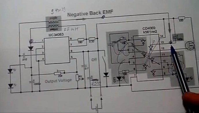
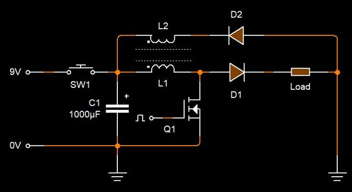
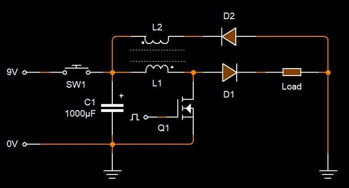
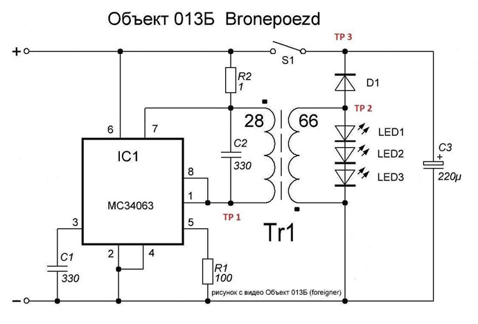
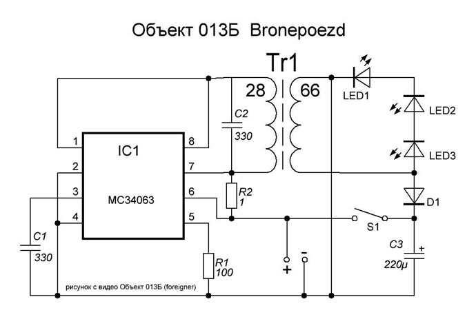
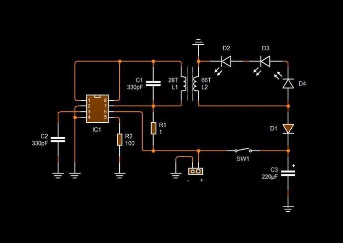
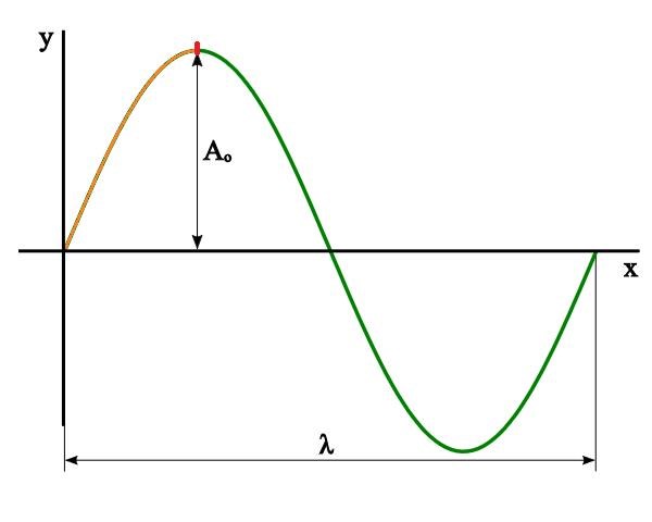
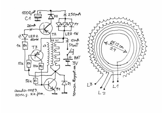
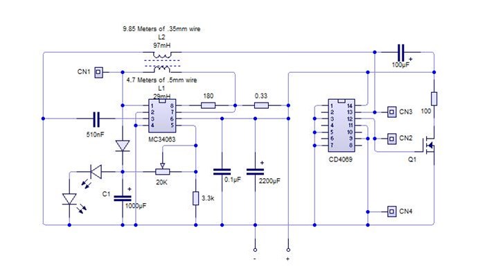
1/4 is 0.25, now the MC34063 IC has a timing inside the chip. again all this is speculation, but I believe, the chip switches at Time t, so Coil L1 must match the 1/4 Wavelength, and L2 is a Harmonic of the Fundamental. We have covered Antenna Theory already here.
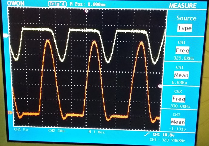
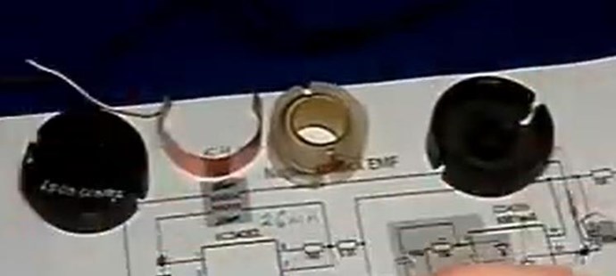
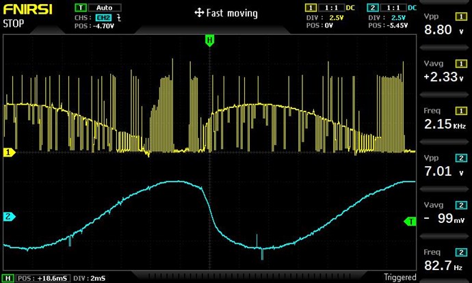
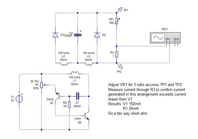
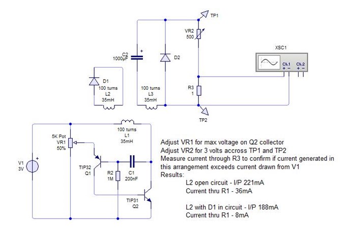
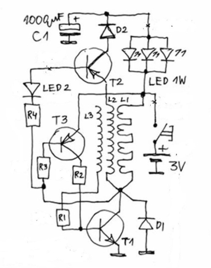
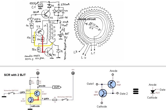
Lets look at Akula's figures:
So, lets ask, what's the Output Impedance? We can only guess on statistics, lets use this chart:
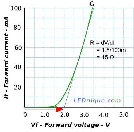
Back to back, we have 30 Ohms approximately right?
Lets use the Aboveunity.com Member Calculator to see the Coil characteristics:
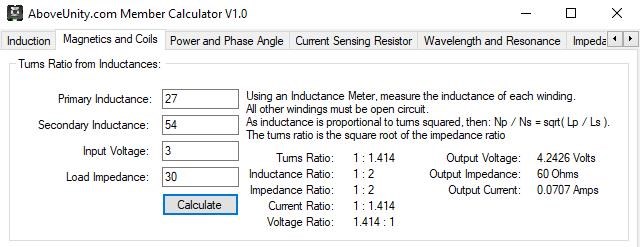
So, turns ratio, are 1 : 1.414, so we could say, 1 / 1.414 = 0.707 and 1 - 0.707 = 0.29278, so not quite our 1/4 wavelength... Which is 0.25. Confused?
I really wish someone would chime in with more experience than me to help and correct me when I am wrong!
There is some guess work involved, that's all there is to it! I am no expert, that's why I said what I did, I am no expert, I have to guess on things. I cannot set any example if I do not have all the answers, I can only try to help. 
I am sorry, my lack of Electronic Skills, and lack of answers gives me, and all of us, a disadvantage, but I am fairly confident that's part of the answer.
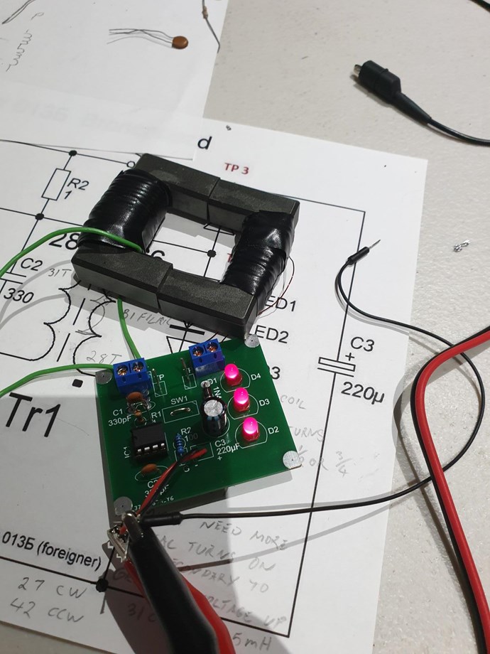
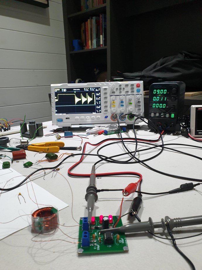
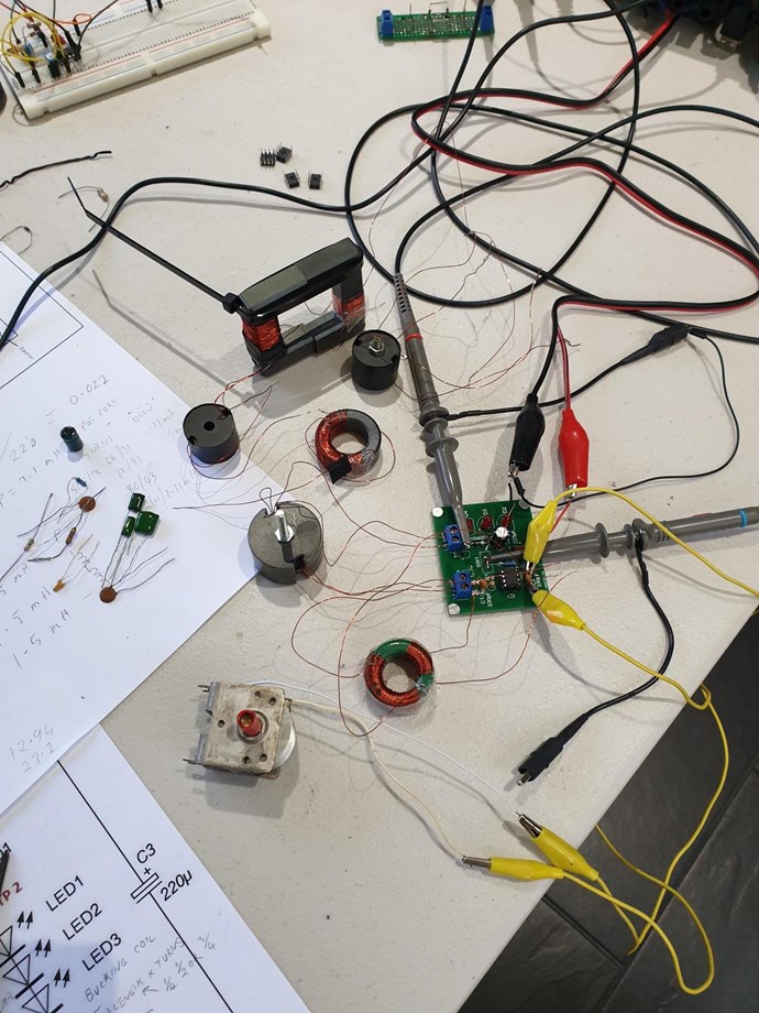
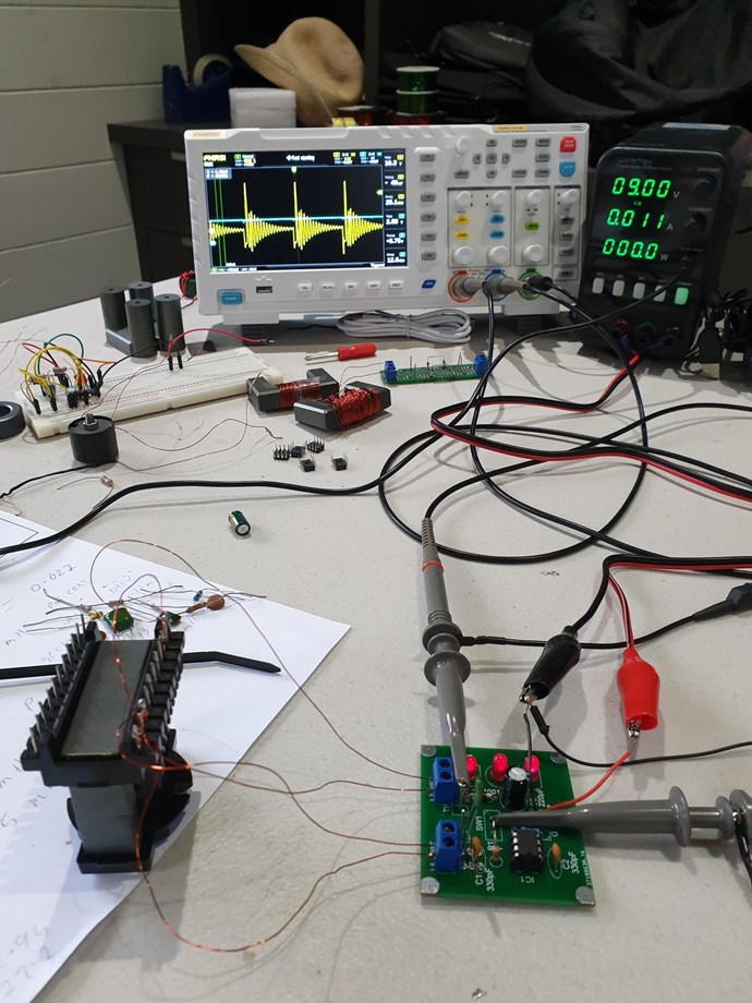
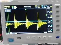
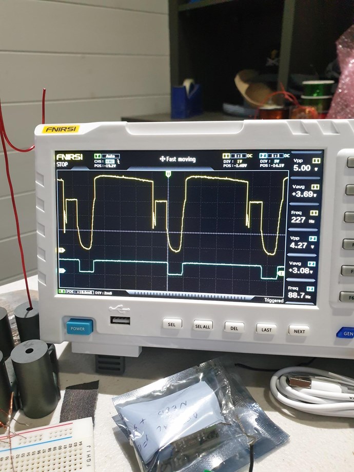
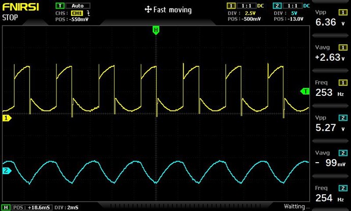
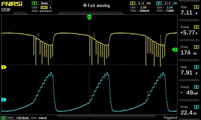
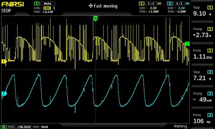
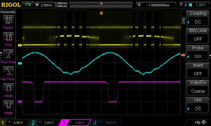
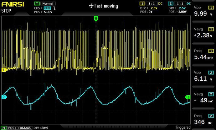
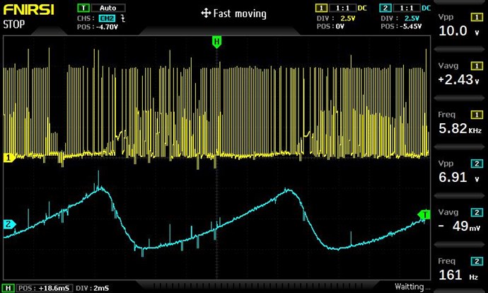
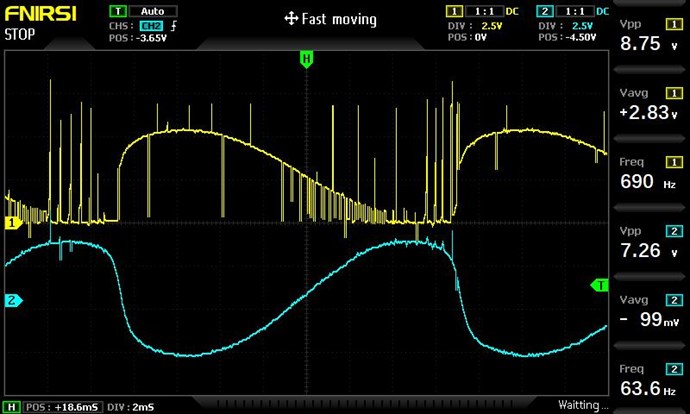
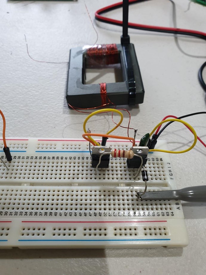
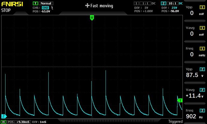
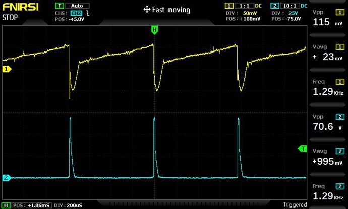
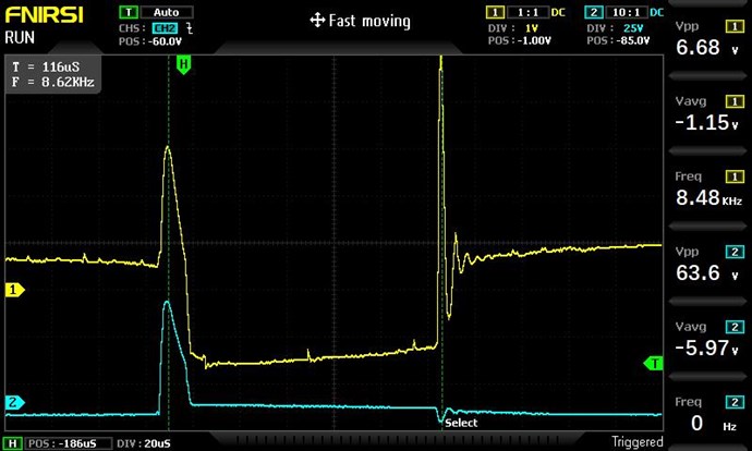
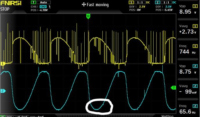
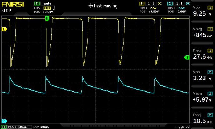
Can anyone point out the issues I have with my Waveform?
Best Wishes,
Chris


 3
this now does not work at all not yet
00:40
caught up completely all the signals were checked
00:43
pieces working principle forming
00:47
low frequency resonance in or seconds
00:50
that is, here is our faces of cultures weekend and
00:55
this capacitor
00:59
that is what we have here right here
01:04
there she is
01:16
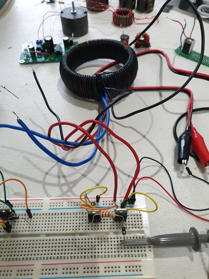
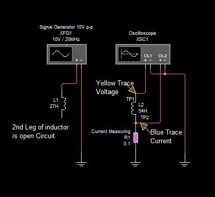
so we have a series here
01:26
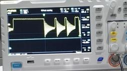
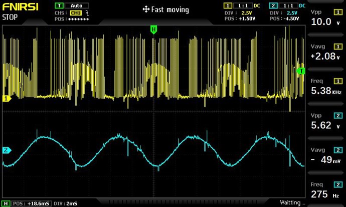
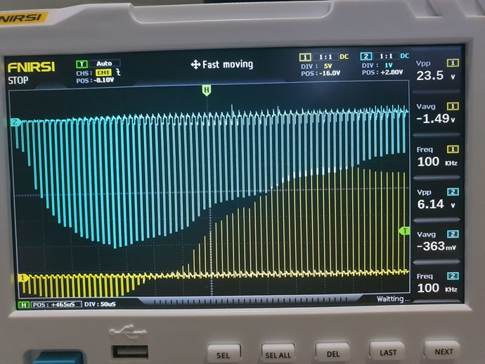
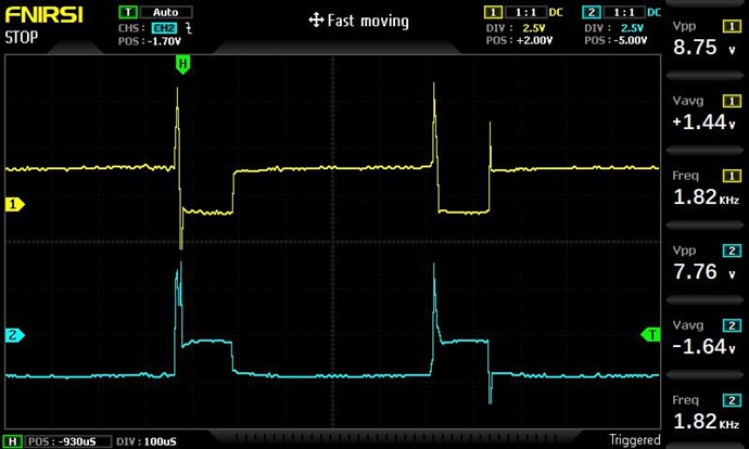
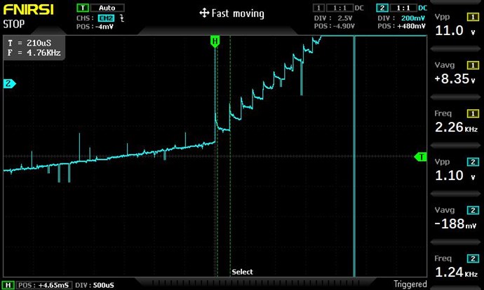
we see the bursts of impulses
01
3
this now does not work at all not yet
00:40
caught up completely all the signals were checked
00:43
pieces working principle forming
00:47
low frequency resonance in or seconds
00:50
that is, here is our faces of cultures weekend and
00:55
this capacitor
00:59
that is what we have here right here
01:04
there she is
01:16
so we have a series here
01:26
we see the bursts of impulses
01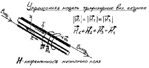
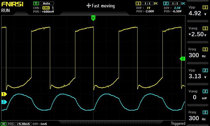


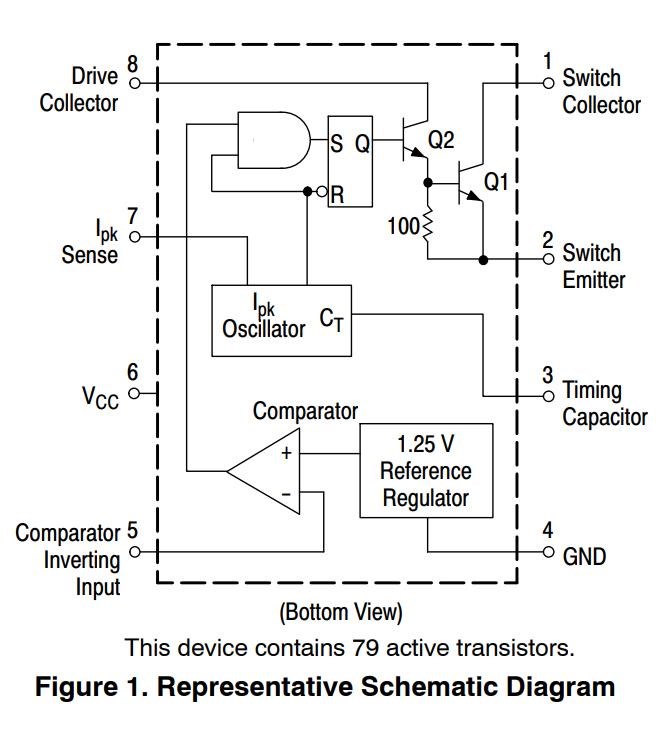


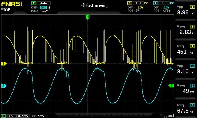


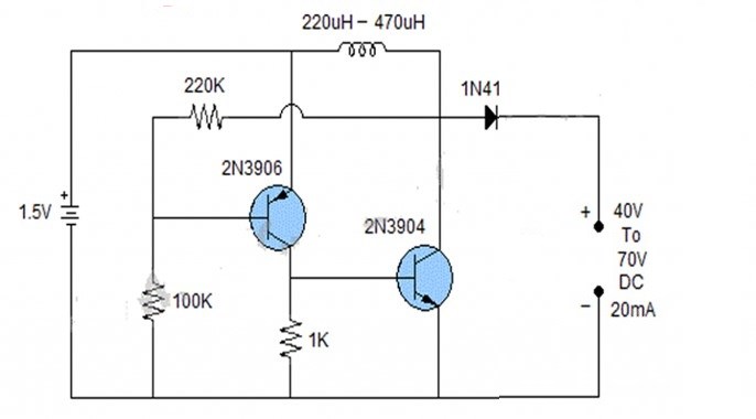
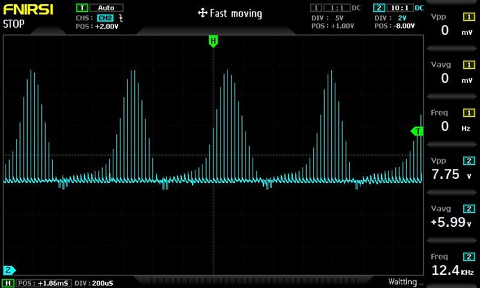


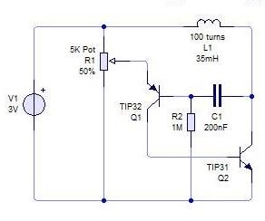

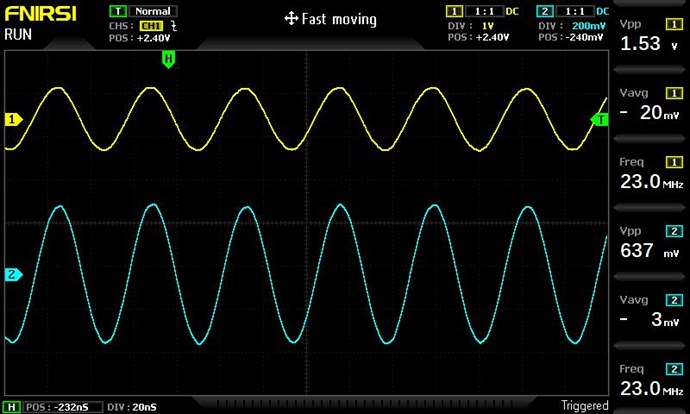


 I tried further tuning via the timing cap on pin3 of the MC34063, but the effects were minimal.


---open-tesla-research.jpg?width=20&crop=0,0,20,20)


