Vidura
posted this
17 November 2020
- Last edited 17 November 2020
Now I think to understand why the ¼ wirelength in the inductor, but first I will share the fundamentals of the hypothesis in general, so you can understand.
As we all here know certainly, to have real power from the output of any AU device we need to have current and potential, with a reasonable phase coincidence. In this particular case the current is provided from a conventional stepdown stage, and then transferred to a resonant tank, where a considerable reactive power is stored. Nothing magics for the moment, well known technology. And if we consider now the transfer to the output coil (grenade), say with a load connected, all we would achieve is depleting the stored resonant energy, and loading the source transformer. Also, as our experiences with (partially) cancelling coils have shown, it would be likely, that the voltage at the output would be too low to power a load properly. We have to bring up the potential to get kilowatts out of the device. Now this is done in the BTG with a unique and very smart method. To understand how this is done, we have to dive a bit deeper in antenna theory. I will publish this part also in a general accessible thread, so others can benefit.
So, let’s talk about antennas and coils. Teslacoils will be used as example, because they are excellent E-field antennas.
Most of all antennas used in broadcasting, and Rf transmission are E-field antennas in contrast to the B-field antenna or magnetic loop antenna. The principal layout difference is that E-field antennas have at least one open ended conductor or rod (but not always....) The B-field antennas always are built as a closed loop, because current flow is needed for transmitting or receiving the magnetic field of a signal. In some cases, a high permeability ferrite rod is placed inside the magnetic loop, in order to concentrate the weak magnetic field of the RF signal. This is the case for example in the long wave or mid wave range radio receivers.
In the image below you can see a drawing of a Marconi antenna, which is a typical quarter wave E-field antenna:
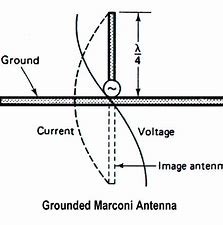
The graphs showing approximate distribution of current and voltage. At the top section of the rod the voltage is at maximum when in resonance. The current is at maximum at the feeding point on the bottom and at the ground connection of the feeding wire. If we would replace the strait rod with ʎ/4 length by a solenoid with the same length, which sometimes is done because the extended rod could be very large in lower frequency ranges, then we still would have a functional antenna with the same resonant frequency. Although the performance would decrease some compared with the extended version. Despite that this kind of antennas can have a significant current flow on the feeding point, the produced magnetic field is negligible, due to the small inductance, and the cube of distance law applying for magnetic fields. They are transmitting and receiving by resonant coupling thru the E-field.
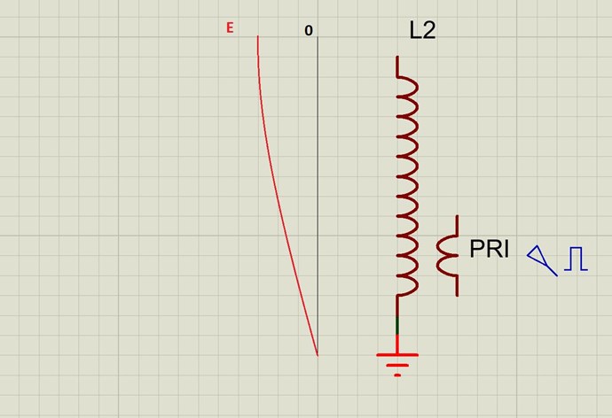
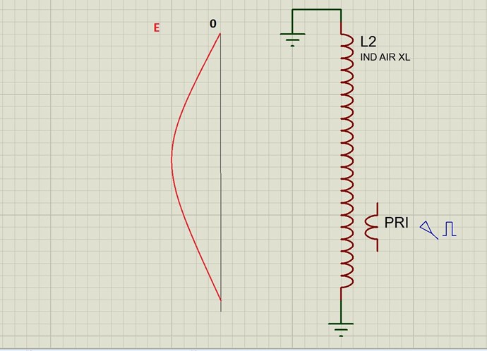
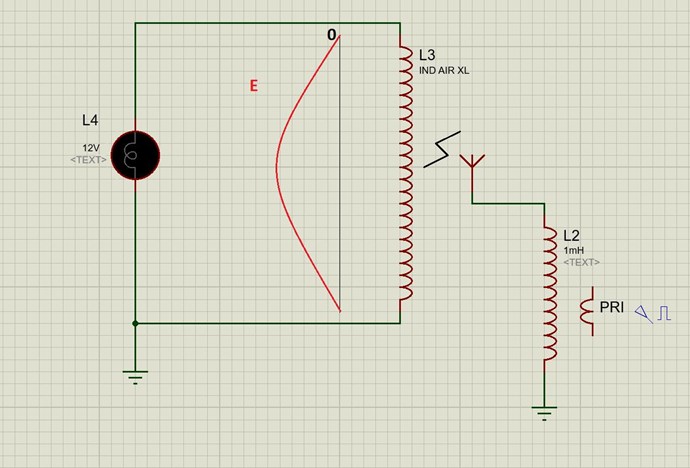
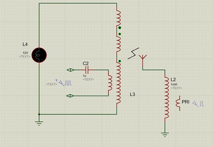
In the next image you can see a schematic of a typical grounded quarter wave Teslacoil, which is much the same, except that the feeding is done by transformer coupling and a primary coil. By the way some radio transmitters use similar technique.
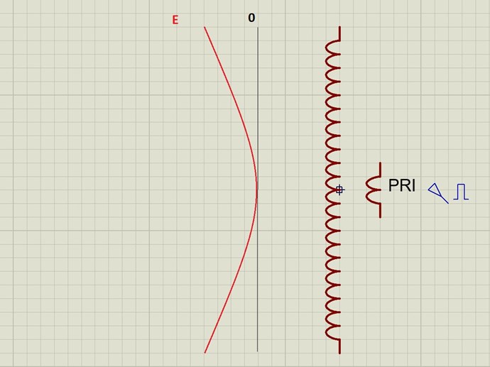
Now imagine what would happen if we remove the ground connection from this teslacoil. The pattern of the E-field would change completely, and provided that the same L2 wirelength remains, the resonant frequency will double. Or we can use an L2 of twice the length, maintaining the same resonant frequency. But now we have a half-wave TC.
And an antenna corresponding to this wave pattern would look like this:
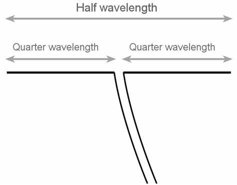
So, a half-wave TC can not be grounded? It can, of course. We could add to this very same layout a centre-tap to L2 and connect it to ground without changing the field pattern.
Or we can connect the two open ends to ground, which would invert the pattern of the E-field, like illustrated in the next image.
This is by the way an example of a closed loop E-field antenna. If needed an aerial could be connected to a centre-tap, where the maximum of the E-field appears.
will continue soon
Vidura


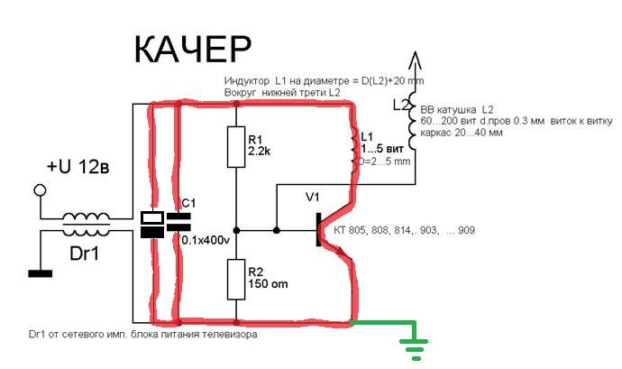
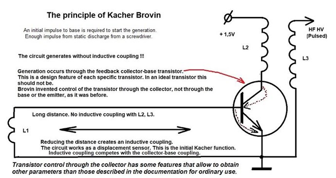
 ). But I will repeat some of the important experiments and record them as I have time. I was quite surprised when i read the document from mr. Brovin about the Katcher effect. It is very different from a normal feedback(blocking) oscillator. You can have a look at this (machine)translated document attached below:


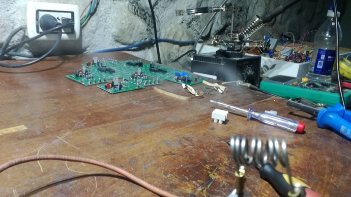
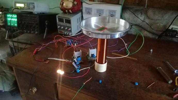
 after all I have time for it as I am waiting for parts to come for other setups.


---open-tesla-research.jpg?width=20&crop=0,0,20,20)


