

Capacitor recharging
How to recharge a capacitor after having used the starting voltage?
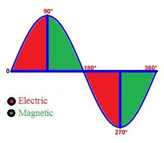
We need to understand the behavior of a coil in the presence of a charged capacitor, I start the thread with an image of Vladimir Utkin which I was inspired by for my research and he has all the credit for it.
Image I focused on.
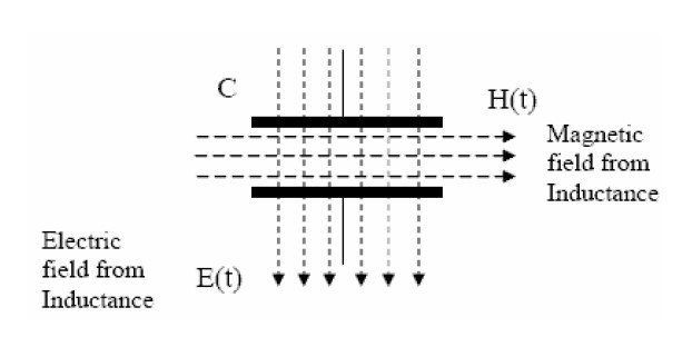
Important quote:
You need to charge the capacitor using the electric component of the electromagnetic field of the inductor.
The best way to understand what is going on inside the capacitor is to do this very simple little experiment.
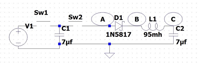
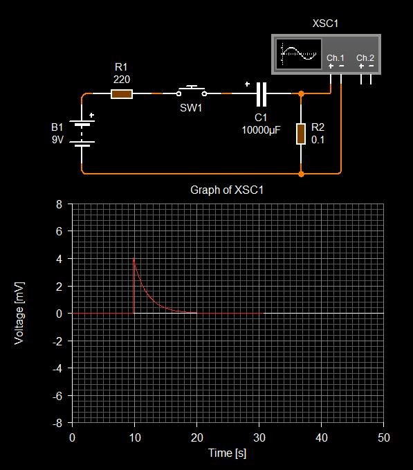
Here is a very simple little diagram:

We charge a capacitor at +9 volts, and I discharge it in a coil via a diode (schottky) connected to an inductor. Very simple and uncomplicated instead of using switches you can do it manually it works great too.
We charge the C by closing Sw1 first to charge the Capacitor and we open SW1, then we close SW2 and importantly, we let it close because that's where the magic happens.
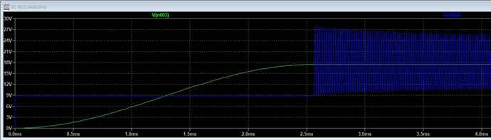
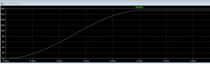
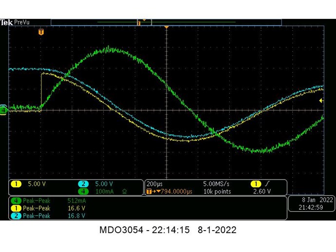
On the oscilloscope what we observe:
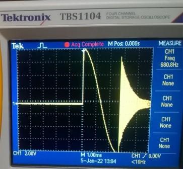
At the moment when the capacitor is connected to the diode it discharges from the maximum of its charged voltage and the positive curve appears, we note the starting hysteresis point followed by the discharge with time constant of +9 up to 0 volts (1.47 millisecond).
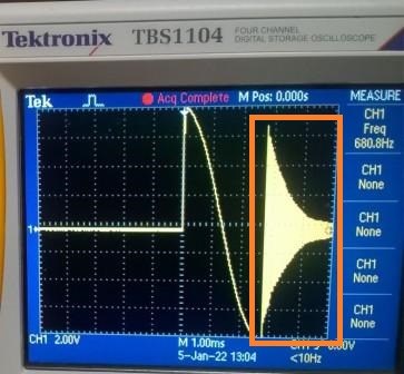
The negative curve is the interesting part and this is where we agree on most of our research especially when it comes to capacitor recharging.
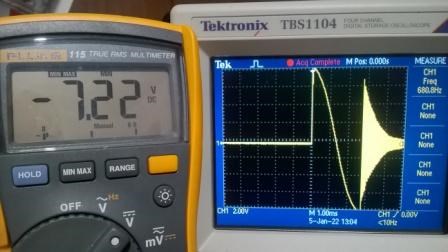
When the capacitor is completely empty, the coil produces, depending on the inductance used, a reverse voltage (BEMF, electric field) from the magnetic field stored by the inductor.
We have here in a first phase, the discharge time (time constant) of the capacitor produces in the coil a rise time of the magnetic field in the inductance. And in a second phase, the decay time of the inductance's magnetic field produces a reverse voltage that recharges the capacitor in reverse polarity.
At zero crossing, the magnetic field stored in the inductor returns to the capacitor as a voltage (volt). This voltage is now negative from 0 to -7.22 volts and its maximum is almost equal to the original voltage minus the resistive losses of the circuit components. Viewing on the oscilloscope is a breathtaking detail of the behavior of two passive elements with at the end an onset of resonance from the diode and parasitic elements of the circuit.
We can say that time is doing things well for us and that this simple little circuit is close to unity.
So after understanding what is going on we could better try to understand and learn to work with Lenz's Law and use it to our advantage. As Chris has often demonstrated, it can now be visualized.
For those who would like to repeat the very simple experiment your oscilloscope must be in SINGLE mode, most oscilloscopes today have this option, it takes an instant depending on the programmed trigger point at extremely fast speeds. If you need help asked, I will accompany you.
Taking advantage of it in our research allows us to visualize this effect and helps us better understand the very important effect of capacitor recharging in a circuit using a C and an L.
It should be remembered that a capacitor is a passive source and it only produces when charged. Let's keep it simple for now, just trying to figure out what's going on with the image the oscilloscope produces.
Other observations to follow.
ùjagau


 Is F6FLT MileHigh? Been there done that! Won already!


---open-tesla-research.jpg?width=20&crop=0,0,20,20)


