Captainloz's Asymmetrical Re-gauging Experiment

  • Topic Is Sticky
  • 9.9K Views
  • Last Post 02 October 2021
Captainloz posted this 23 August 2020

Hi Guys,

Sorry I haven't been contributing lately. I think this video is insightful. I'm pretty happy with the way things are progressing. I took Chris's advise and went back to what I was having success with. That was good advise!

I still want to try setting up the L1 coil in series resonance.  Remember series resonance is supposed to give better voltage and parallel resonance gives better current out.  I also need to work on impedance matching.  I love the analogy of impedance matching to a torc converter. I still don't fully understand how to do this yet but that's what I'm currently studying. 

Cheers,

Loz

Order By: Standard | Newest | Votes
Chris posted this 24 August 2020

My Friends,

I did not have a lot of time this morning and since then, have reviewed CaptainLoz's full video. Awesome Work Loz!

Loz has nailed Partnered Output Coils! He should be very proud! A huge achievement! Well Done CaptainLoz!

Disconnecting L3's Diode and seeing the Lights go almost completely out, is 100%  how this should work! A tell tail guide that the Two Output Coils are Interacting how they should.

Loz full Credit My Friend, Well done, you should be so very proud of your achievement!

If you feel, at sometime, you could drop the thread down to Tier I, for all public? Only when you are ready though!

I would like to ask all members, please support Loz's Work, Please replicate and share your results on your own dedicated thread.

Please beware, this is going to move very fast all of a sudden, soon many people will require help. I ask all members, please help others as we have here on this forum. This is the only thing I ask of you. All of Humanity needs to have this technology available to them, its super important!

If I may add, Input Circuitry like YoElMiCrO has shared with us, at the resonant Frequency, may be useful also:


Of course, L x C = T in Seconds and aiming for a pulse like this:


Congratulations Loz! 

My Friends, you all are awesome and I have huge respect for you all!

Best wishes, stay safe and well My Friends,

   Chris

Captainloz posted this 24 August 2020

Thanks Guys!

To be very honest I wouldn't be this far without aboveunity.com.  This forum is the best!  And I really appreciate being a part of it!

Cheers,

Loz

Captainloz posted this 19 September 2020

Hi Cd,

I appreciate your opinion. I've gone back to the 0.1ohm resistors. I'm now using brand new ones just encase I damaged the last ones I had.  By the way, I love the quote by Steven Mark you have on your posts, so true!  There are so many different ways to make them interact with each other.  Just finding the best way is the trick. Hahaha!

Hi Guys

In this quick video I've moved the air capacitor to the L2 coil, it gives a very nice rise in energy.  Now, because the capacitor is in series with the L2 coil I understand there are possible phase angle inefficiencies that could show a slight measurement error.  However I believe the scope is taking that into consideration. I think I'm showing enough AU to allow for any errors caused by Air Capacitor Parasitic Capacitance.  Take a look and see what you think. 

I'm going to move on from this now because there are other things I want to try to make it even more efficient.

Cheers, 

Loz


Jagau posted this 23 August 2020

HelloLOz

I join Chris to congratulate you LOZ, very nice demonstration.


A lot of material to study this is great.

I took the time to study it, I just got back from a great fishing weekend.

I think we have a very good team here, Chris you can be proud too.


Jagau

Atti posted this 24 August 2020


Hi.

If there is an intention to share more, then some explanation for physical implementation would also be needed. So the winding directions which is marked in the picture. But if you want.

Atti.

Chris posted this 24 August 2020

My Friends,

Simplicity:


Loz has done an awesome job!

Remember, each Coil is an Antenna! No loop backs are needed, as Each Individual Coil, L2 and L3 oppose each other and this opposition makes for the so called Non-Inductive Component we often see in the Kapanadze Devices. The Turns Clock Wise and Counter Clock Wise are best thought of as separate Coils, this is L2 and L3 individually.

The method CaptainLoz uses has a better Coupling Coefficient and the Output will be greater as a result.


My Friends, Simplicity, keep it simple and don't let your mind over complicate this!


There is no Magic, no mystery, its just a few Antenna's, wound in a Helix, with a lot of EM Radiation at the 1/4 Wavelength! Electromagnetic Resonance.

I want to thank Loz for sharing his work, a massive success! Some are not ready to share their work, with similar successes, some have self running machines. So this is a big step forward and many here now have a new bench mark to follow.

Best wishes, stay safe and well My Friends,

   Chris


P.S: Your Video is being posted over at ou.com by member Color. I have dropped this thread down to Tier I from Tier II as its not something we can work on in private now.

Yes the skeptics are already out, we need to try to ignore them. You all are safe here! I will Ban them if they come!

Captainloz posted this 25 August 2020

Hey CD,

I use the wavelength frequency of 37.241 Mhz / 444 = 383.76 Khz (harmonic). I just picked the frequency based off of what capacitors I had on hand.  I think we just need to make sure whatever frequency we choose is a harmonice of the wavelength, of the length of the coils. 

Cheers,

Loz


Captainloz posted this 25 August 2020

Hey Chris,

It's fine for it to be on Tier1. I thought I had this video on a private link.  It's all good, let's get it out there! 

Cheers,

Loz

Captainloz posted this 25 August 2020

Hi Atti,

I started winding the coils from each end using the right hand grip rule, (current pointing into the middle).  When you get to the middle just fold the wire over and come back on itself 7 turns, then fold the wire again and wind back to the start.  So it's just 2 layers.

The torid OD is 62mm, ID is 35mm, 11mm thick.  I got these about 10 years ago and I can't find the record of the type of ferrite. I'm pretty sure I got them off Ebay.

Yellow wire is 14 AWG (L2 & L3)

Red wire is 2.5mm (L1)

General purpose diode's 6A05 - 1212

2 x 14V bulbs

1 x 12 V 7.5 wLED bulb

2 x WIMA 2kV, 2nF caps 

Cheers,

Loz

Chris posted this 25 August 2020

Hey Loz

Regarding:

Hi PM,

I'm reading the input power right from the Rigol power supply.  Why is that not an accurate way to determine the watts being consumed by the input?  That's why I purchased this power supply I was sick of figuring out my input watts.  The output is being read by the scope.  One probe is across a 0.1 ohm resistor set to 1x and 10x on the scope. Ohms Law measurement of: 1 x 0.1 x 10 = 1 Ohm. Meaning if you have 1 Volt measured across the 0.1 Ohm resistor it is 1 Amp, because 1 x 1 = 1.  The voltage is being read across the load.  If you watch the video to the end you see me put the scope on Averaging sample rate.  It still shows I'm getting more out than in.  If I'm not taking the readings correctly please advise.
Thanks,
Loz


Don't let them get at you!

I have a Rigol DP832 Precision Power Supply, same as yours. I have calibrated my scope and you know what, after my Scope Calibration, I found my DP832 to be spot on!

Don't forget, we get Rigol Certification with our Power Supply's! This is to say that Rigol knows a fair bit more than some person yelling Measurement Error from the Roof Tops!

Greater than 10 Watts on the Input, that is not Measurement Error! If we were debating 0.25 watts, then that would be a different story!

Please ignore them, they have sour grapes! They actually don't know as much as they allow others to believe, if you want an example, read through the link that was posted.

I fully support you mate! I know whats possible with these machines! They don't!

Best wishes, stay safe and well My Friend,

   Chris

Chris posted this 26 August 2020

Hey Guys,

Just a reminder, Loz gave us measurements on L2 and not from L3. L3 must also have the same Power in this Coil, because of Lenz's Law, This Coil, L3, is the Yang in the YinYang Relationship ( L2 and L3 ).


The YinYang is important to think about here, Symmetry between L2 and L3 but Asymmetry back to L1.

Thank You to all, for Supporting Loz! Thumbs Up and Favoriting this helps show your support!

Best wishes, stay safe and well My Friends,

   Chris

Captainloz posted this 26 August 2020

Hi Guys,

I was playing around last night by upping the voltage to 65 volts and I've done some damage. I've blown out my mosfet(s) and it looks like diodes as well. 

Max, that's a great point I will do that. Although I don't think that will not show the power loss in the diodes.  They get very hot so are drawing a lot of power which is shown across the resister, if I connect the DC power supply directly to the load I won't see the power consumption of the diodes, which is real power being generated by the coils but not being consumed in the load. That's why I think I'll need to get the output up to over 3 x before it will self run.

Thay, good point! That's may help with what I just said above to Max. Thanks!

YoElMiCrO, I'm not sure I understand but I'm planning on using the Math function on the scope. Itsu sent me this video link 

which I watched last night but still need to try.  As soon as I get the circuit back up and running I will try this.

I will say to everyone that in all the years I've been doing this, I have been measuring input and output basically the same way (maybe incorrectly) and this is the first time I've been able to measure over 20 watts extra out. So even if I'm making a measuring error it's still the best experiment I've ever done.  Obviously I'd like to see a lot more power out, but this is where I'm at. I encourage you to replicate this and see if you get the same results. 

I know I not the smartest guys on this forum so if I can do it you can do it.  As Chris says "keep it simple"!

I need to keep it simple because I'm just not smart enough to make it complicated. Hahaha!

Lastly, I find it really hard to make time for this forum so if I go quiet for awhile it's just because of life responsibilities. But I'll do my best to keep contributing as much as possible.    

Cheers Boys!

Loz


Chris posted this 27 August 2020

My Friends,

In the thread: The Input Coil, I posted about the Input Coils importance.

I don't want to be picky, Loz has done an awesome job, and most definitely don't want to confuse anyone, so some might be best to not read all this Post perhaps. I only aim to help!

The Input Coil has an optimum length and therefore operation frequency: One Quarter the Wavelength or close to the Partnered Output Coil Operating Frequency. The Input Coil is directly related to the Partnered Output Coils, frequency wise, thus length wise.

This means, the Input Coil's length is the same as one Partnered Output Coil / 4, approximately.

Loz already pointed this out in the video.

Optimising the Input Coil Length and operation will maximise the over all efficiency and make the Input go right down, even go Negative.

You all are awesome and you all should be so proud of yourselves! Humanity has never had an opportunity like this ever before!

Best wishes, stay safe and well My Friends,

   Chris

Vidura posted this 01 September 2020

Hey Loz, Just wanted you to know that I have made mistakes with measurements some time ago. It is certainly a bit frustrating if we believe that we made it, and suddenly the bubble bursts when we realize that something was wrong. But keep up your great effort, be confident that it is possible, there are several Devices that are showing AU and they can be made self sustaining. Personally I have become a bit more cautious after my measurements mistake, and try to always double check with different methods when I got promising results. I found it very useful to put some analogue meters, which proved to be less sensitive to interference and quite reliable . The Scope is an amazing instrument, but I found in some special cases no explanation for the response of the screen. I wish you all the best, be confident, we will be successful. Vidura.

Chris posted this 03 September 2020

My Friends,

Only a few more steps here and this could prove to be very beneficial!

A measurement error just before the Precipice of Success, like I said, Input Coil adjustment to get 1/4 Wave, is a dire blow to Success! A dire discouragement on the Precipice of Success!

Success comes after Understanding and Hard Work:


I do hope we all take this work serious, and do not allow measurement error discourage progress.

Best wishes, stay safe and well My Friends,

   Chris

Captainloz posted this 14 December 2020

Hi Guys,

I agree the measuring protocols we have here are solid and should be followed. Trust me I learned the hard way! I embarrassed myself a couple times...

The big problem I keep having is putting too much current through my measurement resistors. It does have an affect on their accuracy if you get them to the point when they turn blue from the heat. 

I've been working on a couple other devices that didn't pan out... so now focusing on Asymmetrical transformer again!  All roads keep leading me back to this type of transformer. wink

Cheers,

Loz

Chris posted this 23 August 2020

Hey Loz,

My Friend, awesome work! I am very proud to see your great success! Very nice to see! Thank You for Sharing!

All here learning, please take special note of CaptainLoz's experiment, this is very well done, very professional!

We, our Team, the support we each give each other, it is first class! We are all so lucky to have such a great bunch of people around us! You all are awesome!

Best wishes, stay safe and well My Friend,

   Chris


P.S: I have moved this important experiment out from: Nonlinear resonance to this new thread.

Jagau posted this 25 August 2020

Hey loz

Thank you for sharing your research on the Aboveunity.com site.


As you can see, it is only here on this site that things really happen with real experiences. Contrary to the other sites which do not have anything to put under their teeth it must not be easy for them to see that here we succeed, the problem over there, there is that there is a lot of blah blah blah and not enough real experiences .


Keep it up Loz is how we develop with real things to be verified. Don't let yourself be influenced by those who can do nothing but criticize those who succeed.


As Chris has already said, we are very advanced here.

 P.S.
I see that you noticed a very important little detail that I also noted in my research, the change in load impedence brings a change to the source it's real Loz


 I'm still studying your video, very interesting and a lot of material, thank you


Jagau

Captainloz posted this 25 August 2020

Hi Guys,

Thanks for the support!  Obviously this is just the start, there is still so much more to do to get this transformer to self run.

I'm finding a high percentage of the power is being consumed in the diodes. I also tried a bridge rectifier for the output and that uses too much power. 

As nice as it is to see the measurements on the scope. It's still a long way off being a self runner.  Also, I'm still open to the possibility that I'm making a measuring error (although I don't think so).  I've asked a physicist professor friend of mine to take a look. We have discussed this before and he didn't take me seriously, but now I have something to show I'm hopping he takes a serious look.  We need this to become mainstream!  We need to show Lenz's law can be broken with Asymmetry.  I think this experiment clearly shows that.

Cheers,

Loz


Atti posted this 25 August 2020

Hey Loz!

The winding process is extremely important. We can see from the various works.
I don’t want to mention anyone in particular, as everyone’s work is important and instructive. So thanks to all the active creative people!
Measurement is important but not essential. It is important because it confirms the right path.
Such results lead to the path to a stand-alone machine.
Don't worry about who says what. Do it as you see fit.
In my opinion, everyone can learn from what is presented here if they are serious about building a machine.
I’m still studying the video and posts.

Atti.

Chris posted this 25 August 2020

Hi Guys,

Thanks for the support!  Obviously this is just the start, there is still so much more to do to get this transformer to self run.

I'm finding a high percentage of the power is being consumed in the diodes. I also tried a bridge rectifier for the output and that uses too much power. 

As nice as it is to see the measurements on the scope. It's still a long way off being a self runner.  Also, I'm still open to the possibility that I'm making a measuring error (although I don't think so).  I've asked a physicist professor friend of mine to take a look. We have discussed this before and he didn't take me seriously, but now I have something to show I'm hopping he takes a serious look.  We need this to become mainstream!  We need to show Lenz's law can be broken with Asymmetry.  I think this experiment clearly shows that.

Cheers,

Loz


Hey Loz,

There is always room for improvements! So yes, I agree!

There is always the possibility of measurement error, we all make mistakes. However, you have done nothing wrong from what I can see! I have checked your measurements and see nothing wrong! Everything is good! I cant tell if probe settings are 1x or 10x, but I saw you checked and double checked!

What is obvious when there is no other explanation, leaves only the obvious left, you are measuring excess Energy in your Machine! You have everything right! There is no Error!


It is really important that we are not so fast to pass this by!

We must trust ourselves, trust our abilities and have faith in what is possible! Let NO ONE Dismiss your work, but at the same time be open minded. As you are already!

Don't let any one tell you that you have it wrong, because, if you have it right and you dismiss it, you have wasted your years in research for nothing!

Stay Strong and stay focused My Friends!

Loz has Partnered Output Coils exactly Right, This is how they work, as Kapanadze shows, Don Smith shows and many more before us! Please everyone, get on board with this, please support Loz's Work! Please I ask you all to pass this on to those in front of us, new comers. Soon they will come in hordes!

NOTE: What we are sharing is much simpler than many of those before us! Because of Diakoptics! Some researchers in the field have been doing this for 20, 30, 40 or more years, so a bad case of Sour Grapes is going to be common! We must ignore these people that have nothing after so long in the field! They will try to destroy our achievements!

My post here, may be of help to some.

If we do not do this now, this could be Humanity's last chance!

I am so proud of you all! My Friends, You are the strength the world needs!

Best wishes, stay safe and well My Friends,

   Chris

YoElMiCrO posted this 26 August 2020

Hi all.

@Captainloz.

I have seen your video quickly, if you are interested in another opinion
I will calculate the output power applied to the bulbs,
as the waveform is complex, time must be integrated
about voltage and current, then we take the average and from there
we extract the active power applied to the load.
Regarding the power that your power source reflects,
there is no doubt about it.
Thanks for sharing your experiments, this is the forum to do it.
It's just another opinion, because the more we are, the better.

Thanks in advance.

YoElMiCrO.

Maxxon posted this 26 August 2020

Hey, Loz .

You can easily verify by connecting all your load lamps directly to your power source and compare the lamps current draw with same voltages you had on your device output.

Max


thaelin posted this 26 August 2020

Hey Loz:

   Try ultra fast diodes and gang up say 4 of them to lower the voltage drop across them.  Like doing with two resistors, in parallel, they will be 1/2 the value.

thay


YoElMiCrO posted this 27 August 2020

Hi all.

@Captainloz.

If you want try this.

In this way, do not open any type of doubts regarding
to the power at the load, since the capacitor will store
all the energies that circulate through your secondary.

I hope it helps.

YoElMiCrO.

Captainloz posted this 30 August 2020

Hi Itsu

Thanks for your video. Here is the reply-  

I still can't seem to find where the M (mean) data is displayed on my scope.  However as you can see if we take the average amperage reading my efficiency drops drastically, however I'm still showing a small gain.  Note; I do have my circuit set up a little differently than the last experiment, but it's basically the same.

Cheers,

Loz

Chris posted this 30 August 2020

Hey Loz,

Have confidence in measurements!

I have posted a Post to the Measurements Thread to help you out with taking measurements. The protocols are right so please be confident!

The video:


Please go and read the post, there is more there!

Keep Input and Output Measurements separate, state them as such: Input or Output Measurements.

Keep your Chin up My Friend, your'e doing fine! If you follow the protocols I have posted for you, you wont go wrong!

Best wishes, stay safe and well My Friend,

   Chris

Chris posted this 31 August 2020

My Friends,

First of all I want to thank Captainloz for his honesty and coming forward with a Bad Probe.

Second, I want to reiterate my above post, Please verify your Scope and Probes, verify by doing simple calibrations on a regular basis to check equipment. Normally you will be fine, everything will just work and it will be pretty accurate!

Third, I want to say, what Loz has shared here does work! Just because we have seen a Bad Probe, should not discourage us! Especially those learning, the up coming!

Why?

Because many of us have very advanced machines running, based on the exact same technology, some of us have Self Running Machines, here is our Public and Tier II list:


Personally I am a little cut, but I knew deep down, this was on the cards. We all make mistakes, it is inevitable, we are not perfect. We must remember, this is just a crack in the road and we must keep focused and solid in our path forward.

@Loz, My Friend, Please do not worry! This sort of thing happens! Now you know how the scope works and how to calibrate and test the Scope and the Scope Probes. We fully support You Mate, like Augenblick said, no matter what! You are truly on the right track! Please I ask you don't give up! This will work with the right fiddling, you have my word!

The best way to think of this is the same as the BTG, or Kapanadze's Grenade Coil:

Well, Turns Clock Wise and Turns Counter Clock Wise, the exact same basic operation is the same! We must have Magnetic Resonance, which you are 100% spot on and the Voltage must be Increased sufficiently, remember: I = V / R

You saw the Voltage and Current increase under load, this is how it works, to a point. Increase your Load!

It is easy for the Skeptics to have a field day from this sort of thing. But as I said, sooner or later it was inevitable, something would go wrong, but that's life! We have to Motor On!

Evolution is not for the faint hearted! We must push forward to succeed! How many rockets did SpaceX loose before getting to Space?

@Loz, get your scope back on track, throw out Bad Probes, do regular Scope tests and Calibrations, and we will get you back on track! Avoid all High Voltage Testing on the Scope, High Voltage can damage Probes and the Scope!

Best wishes, stay safe and well My Friends,

   Chris

Captainloz posted this 01 September 2020

Hi Guys,

I really appreciate all the support and advice.  And thanks for your understanding. I'm so happy everyone here is actually helping and not criticising.  I will post new results as soon as I can. 

Cheers,

Loz

Jagau posted this 14 September 2020

Hello Loz

I believe the measurement on 0.1 ohm tare resistor is correct.
Do not forget that the oscilloscope measures the voltage only not the amperes, so by the math menu to oscilloscope measures the voltage and converts it in watt. This does not mean that your 0.1 ohm resistance dissipates 17 watts, it is the value of the total power of the circuit.
So your measurement is correct because if we knew each component resistance value (I mean all the wire ends and series component) of your circuit each dissipates power not just your 0.1 ohm resistance.


Your measurement is therefore correct

P.S. This confirms that your circuit gives a little more power than your power supply gives.


Jagau

Vidura posted this 16 September 2020

Hey Loz, Please don't take this the wrong way, Your experiment has potential to be AU. But Chris is totally correct with the wirewound resistor. These components are actually a combination of resistors and coils, which is fine and accurate for DC current only. When dealing with pulsed current or AC, the inductive reactance will add to the readings on the scope, and values will read too high. I will post on the measurement thread some more extensive, also about another issue with shunt resistors, and how to solve this. Regards Vidura.

Captainloz posted this 16 September 2020

Hey Chris and Vidura,

Oh man, I thought I'd had it this time.. Hahaha!  It's all good, the reason I'm here is to learn and hopefully teach others, even if it is from my mistakes. Hahahah! 

Okay I'll swap out the the wire wound resistors and retest. 

Thanks Guys!

Loz

Chris posted this 26 September 2020

My Friends,

I was really hoping to see more here replicate Loz's work and sharing their results.

I know many are busy with Jagau's Circuit. This is really simple however, and also really important. Please don't pass this over guys and gals. Its much more important than many may realise!

Many here have replicated this work, as many already know, its very easy! It is very easy to make improvements, to make this more useful! The Input Coil, the Input Circuit, and the Output can all be improved!

Remember:

  1. The Input Coil can be made much more efficient.
  2. L2 carried Power of X
  3. L3 also carries the same Power of X


We can make this very much better than we have seen in some cases. We have: Asymmetrical Electromagnetic Induction


Meaning, we have: Action, Reaction and a Counter-Reaction all occurring, via Electromagnetic Induction, in one machine at once!

   1: Action = Primary Coil Current changing in Time: di/dt
   2: Reaction = Secondary Coil Opposing the Primary, Current changing in Time: di/dt
   3: Counter-Reaction = Tertiary Coil Opposing the Secondary, Current changing in Time: di/dt


Each "Current changing in Time: di/dt" is a Magnetic Field as we all already know!

Each time we see: di/dt we have the opportunity for Electromagnetic Induction to Occur, and it can be in more than one direction at a time! The propagation of Magnetic Fields can a occur in more than one direction at a single point in Time.

Some of you, here, are very advanced! I know already many have very advanced machines. Everyone wishing to learn more, this is your opportunity!

Best wishes, stay safe and well My Friends

   Chris

Captainloz posted this 26 August 2020

Hey Chris,

If people watch your videos its all in there.  My experiment is proof of that.  I was feeling very frustrated for a long time but then I stumbled on to your youtube channel and it inspired me to keep going.  I actually have your book from way back, I wish now just stayed with it but I went down the Ruslan and Akula rabbit holes for too long without understand Asymmetry and the re-gauging process.  Anyway mate I'm just trying to say you should be proud of yourself. You are doing a great thing here!

Cheers,

Loz

raivope posted this 27 August 2020

Hi,

Just a few hints for the circuit.

Primary coil has C1 for resonance. It will work, but discharging C2 into C1 directly thru the switch is sometimes costly when voltages are different (unless resonance). Trick is to have bifilar primary where you have LC on second primary without other connections. If you do not have h-bridge to drive the primary, you need to protect the single mosfet switch and this LC idea to tap the CEMF is good - having LC on bifilar will clip the non-wanted peaks of the same parallel coil. (but anyway - this primary thing is not a big problem)

Hint2: you are using second primary + diode + shunt for analysis, but in a future you should short this coil without any diode, because diode dissipates energy. Ideal is to have superconductor coil + ideal shorting - thus no dissipation. Trick is that you can have two low ohm (rds-on) opposing MOSFETs sourced together and switched both at the same time. You can keep the diode, but add the shorting-bridge in parallel to it.
Plz refer to my pdf in July 26th: http://www.aboveunity.com/thread/raivope-s-isolated-switching-circuit/?order=all#comment-3e5196a4-d0d8-4ec0-8de4-ac040132371b
Page 15-16 (shorting-bridge).

Captainloz posted this 27 August 2020

Hi YoElMiCrO,

Thank you for the power measurement circuit.  I will give it a try. 

Hi Ralvope,  

Some great advise there, also thanks for the switching circuit pdf. I think I could get much better results with this experiment if I was using a full bridge, I'd like to set up the L1 coil in series resonance.  So many things to try with this set up!

And Guys,

Just a quick point on this set up.The 2nf C3 cap is not needed to see the affect, It only adds a little to the overall output.

And just to be clear with one of the notes on my note pad.  Where I have L1, L2, L3 written down.  I have (red) next to L3 that is just referring to red magic marker I marked on the L3 yellow wire.  

Cheers,

Loz

Captainloz posted this 30 August 2020

So sorry Guys!

Not above unity! Bad probe and measurements! It was not my intention to mislead anyone. Obviously I'm frustrated and a little embarrassed, however I'm glad you guys pushed me for the proper measurements because it's been a great lesson. Chris and Itsu thank you for helping me find the error. I've learnt a lot about my scope but more importantly to check your probes for accuracy.  

I've been using that same probe for ages so all my previous results have to be incorrect.  Chris so sorry for putting you and everyone through this.  I feel terrible about this but I've learnt my lesson. Can you please take my devices off the greater than COP1 list.

Cheers,

Loz

Chris posted this 04 September 2020

Hey CD,

Be careful not to confuse Acoustic Waves and Electromagnetic Waves. We are viewing very different things in some instances.

Ref: Nothing is something by Floyd Sparky Sweet PHD


Floyd Sweet talks about both types of Standing Waves, Electric and Magnetic by changing the way the System is configured.

The Speed of Light ( c ) is still present, but because a Standing Wave has C + -C = 0, same is true of H, H + -H = 0. I believe the next bit is a typo.

Thank You for posting this, it is worth seeing the difference here!

Best wishes, stay safe and well My Friends,

   Chris

Captainloz posted this 13 September 2020

Hi Guys,

I guess some of this thread can be a used as a good example of how easy it is to make measurement mistakes. Haha! Hopefully people will learn from my mistakes!

Here is a quick video showing results with my new scope. My old scope is damaged and won't display the Math data correctly.  I don't think the circuit is above unity. I think I've damaged all my .01ohm resistor blocks because I pumped too much current through them.  The real test will be when I get my new 50 watt wire wound 1 ohm resistors to try in the circuit.  I'll will post results once they arrive.

Cheers,

Loz

Jagau posted this 13 September 2020

I will follow your new data with interest.
Don't worry as you say so well we've all learned. So we keep learning
Cheer LOZ


Jagau

Chris posted this 16 September 2020

Hey Loz,

I am really pleased we don't have a problem! I had a bad feeling is all.

You do awesome work! We all love having you here with us! You are a valuable Member! I love all Members here and will do anything I can for you all!

Right now, you have: COP = 25.9 watts / 11.6 Watts = 2.2327 for an open Core, leaking Flux all over the show, is awesome! Which is the goal! Not achieved, by any other forum!

I know this is possible, and I am very confident you are close, but, please, I ask you, please be very wary with the measurements on those 1 Ohm 50 Watt Resistor. Its Wire Wound for sure. Its really hard to get any conclusive result. As the Voltage goes up on that Resistor, the measured Current will distort more also.

Here is an example:


If Itsu is using the same Resistors, to get accurate measurements he also needs to put them away and use better Precision, non wire wound, Resistors.

You bring up good points! I should have explained I was not totally clear, 5 Watts marked on the metal strip resistor is the rated value, but it can handle more.

You have done an awesome job! Cool accent too! hehehe wink

I care a great deal for you all and am very proud to have you all here with us, doing what we are doing! We are making History, all of you!

I try very hard to give accurate information, but if I do get anything wrong, please, everyone let me know so I can correct!

Also, I want to say, very nice Scope Practices, looking really good now!

You are successful but I really want to stress the Wire Wound Resistor is a real problem. If we want others to take us seriously, we really need to loose the Wire Wound and go back to something others can have confidence in! Even if you need to drop your Input down some to do it.

Best wishes, stay safe and well My Friend,

   Chris


P.S: Sorry, had a few edits.

Captainloz posted this 17 September 2020

Hey Chris,

Yes, the one thing I learnt very early on is to have good equipment to see what's going on. Although it can get expensive when you make a mistake....

I get it my friend, unfortunately I missed your advise on this (in this thread). i had been more concerned in making sure my meters were all calibrated and didn't take the time to think about the circuit. For that I'm sorry i mean no disrespect. I don't mean to take up all your time.

If people are laughing at me then that's on them.  I'm have been very transparent on everything I've done and have not tried to misled anyone.  These are honest mistakes and this forum has been quick to point them out. There is a lot that goes into this stuff and sometimes I just forget things I've learnt a long time ago.  

I'm not sure how I'm making you look like a fool? If anything I've made myself look like one.  

Anyway, I know I'm very close to showing an above unity machine.  And that has always been my goal here. 

Cheers,

Loz


Captainloz posted this 17 September 2020

Hi Chris, 

I do appreciate your support, and understand what you are saying.

I do have people contacting me from other forums. And from around the world, it does take up time I don't have. I don't know how you do it... I am only committed to this forum. I'm continually driving people to join us here to find what they're looking for. 

No I don't have anything new to share right now. However I am sharing all my latest work. I'm trying to make it as easy as possible for anyone to replicate.  I think if we make something that is easy to replicate it will spread very quickly. 

We need to keep it simple.  My goal with this experiment is to show bucking coils / asymmetrical re-gauging in the simplest way possible. I took this idea from one of your videos.

You have given us all the information we need, it's all here! I've just got to stop making silly mistakes and put it out there in way it can not be disputed. 

Cheers,

Loz

Chris posted this 17 September 2020

Hey Loz,

The absolute, most simple place to start is the Circuit and Layout I gave, that you follow:


Action, Reaction and Counter-Reaction


Trust me when I say, there is no simpler way! I have spent many years on this, many years! I have given everyone, everything, you take the path that many others don't!

Don't allow their lazy to become your burden!

The ones that have not gotten themselves banned for bad behaviour, have the opportunity to join us, they do not take the opportunity!

We have no obligation to those that wont help themselves!

I have given the Cheapest, most simple Energy Machine that History has ever seen! No one before me has given such a simple Machine that shows Concept! This is just the start!

Remember, you are at the beginning. Much more ahead, many tips and tricks gained over time.

All information I have shared, has been shared in the Public Domain, since 2011 in a slow release format. Giving every single Human Being on the Planet access to the Technology!

Best wishes, stay safe and well My Friend

   Chris

Chris posted this 19 September 2020

My Friends,

I want to thank Loz for all his excellent efforts! It is great to see such wonderful progress! I am so pleased we have good, very low inductance, very low capacitance, low tolerance, Current Viewing Resistors back in place! Thank You! Remember, we work for the Future, for our Children and their Children! The Unborn! For Humanity!

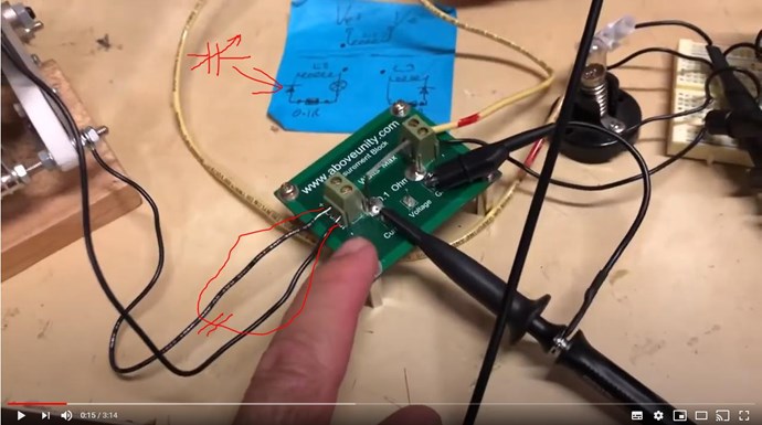
I ask everyone to put their support behind Loz! This video is very good! Even though we admit there are still problems here, we still have a very large margin of error.

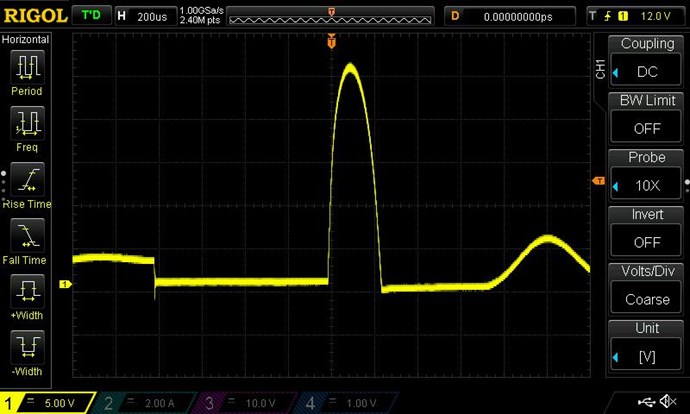
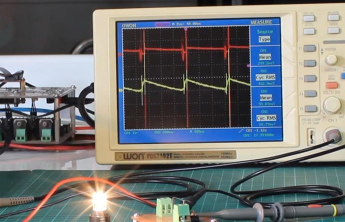
  • Yellow Trace: Current ( 10A / Div ) 7A x 0.707 = 4.949A Not sine, but an approximation.
  • Teal Trace: Voltage ( 20V / Div ) 70V x 0.707 = 49.49V Not sine, but an approximation.
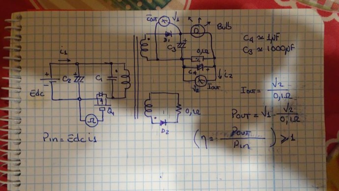
  • Input: 17.106 + 2.405 = 19.511 Watts
  • Output: 37.1 Watts
  • COP: 37.1 / 19.511 = 1.9015


NOTE: The similarity to measurements in Video 5. In the first post.

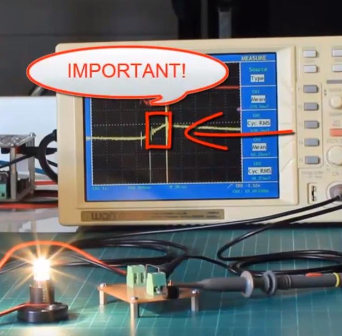
The Scope Bandwidth is 100MHz so less than 1MHZ is well within the Bandwidth! A Brand New Scope freshly Calibrated.

The Input to the Switching Unit really should not be included in the Input as this could be made very much more efficient! So please understand, the 2.405 Watts is currently included on the Input and should not be!

Lets work out the margin of error:

  • Conventional Transformer efficiency: 85%
  • Current efficiency: 190%


So, 190 - 85 = 105% margin. Now if we lost 50% to Stray Capacitance and Stray Inductive losses, and various other losses, we are still 55% over the average Transformer Efficiency! That is: 19.511 Watts x 0.55 = 10.73105 Watts over and above the Input, this means we have: 19.511 Watts + 10.73105 Watts = 30.24205 Watts, with a 50% Error. These numbers should be enough for any Logical mind to warrant more investigation.

Everyone that wants to replicate this and contribute to the effort here, some other things that can be done to make the margin smaller:

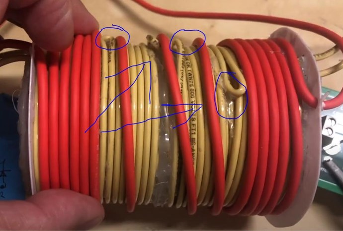
  • Shorten all cables, keep all cables as short as possible.
  • Remove all unnecessary Circuit Impedances: The Input, the 1 Ohm Resistor and other things.
  • Test with and without the Air Capacitor for Measurement differences.
  • At this frequency, look at better possible Current Viewing Resistors: Metal Film or something.
  • Test Temperature of Current Viewing Resistors to make sure they are within the range of accuracy.
  • Look at the application of Ultra Fast Diodes.
  • Look at trying to smooth the Scope Traces some, perhaps Rectify for DC Output and measure.


Please understand, this is early days, many improvements can be made! Tuning and fine tuning is still a path to make improvements on the COP.

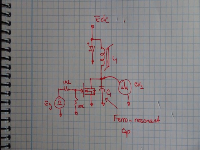
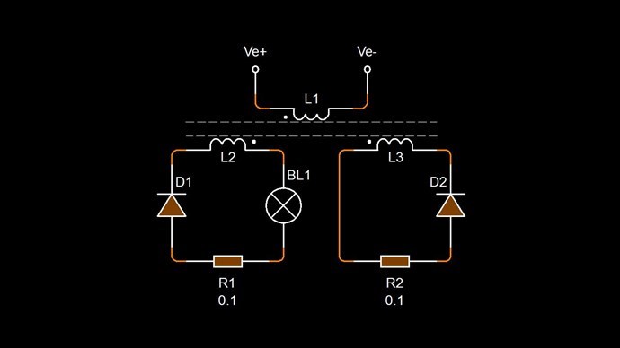
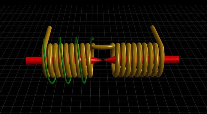
Remember: As I said above, Loz is measuring only One Output Coil ( L3 ), the very same quantity of Power is also Flowing in the other Output Coil ( L2 ) which is still unmeasured and therefore unaccounted for.

Others will try to dismiss this effort, but I am telling you, Loz is 100% on the right path, please don't forget history and what we have seen throughout history: Floyd Sweet, Don Smith, The MEG Team, Akula, Ruslan, Tinman and many others! I promise you, this is the path forward! Even if we find some sort of measurement error here, this is still the path forward! Please go and verify this on Tinman's RTV3 Thread.

I would love to see others joining in and sharing if they can? I know many have another circuit they are working on right now, so maybe in a week or so?

NOTE: At this stage, practicing and improving Scope Best Practices, Measurements and testing equipment is something I recommend, this will help in the Path Forward! I do not recommend looking at Measurements when one is starting, simply because it is discouraging and side tracks Experiment.

Loz, Thank You for sharing! We all very much appreciate all your excellent effort here!

Best wishes, stay safe and well My Friend

   Chris

Chris posted this 19 September 2020

My Friends

Very quickly, I want to point out:


The Resistance of this globe at 12 Volts and 7.5 Watts, is 19.2 Ohms approximately.

If the Voltage across this Globe was 24 Volts, that means, according to Ohms Law, the Globe is consuming the Power of: P = V2 / R = 24 Volts2 / 19.2 Ohms = 30 Watts.

Please be careful not to dismiss this because of the type of Load! A foolish person, supposed to be an expert in Electrical Engineering, has argued with me on this without doing any figures to support the serious malfunction he was having. It so disappoints me, we have so many professionals that are truly stupid!

Could more than 30 Watts really be consumed in that Load - Absolutely Yes!

Best wishes, stay safe and well My Friends

   Chris

Atti posted this 20 September 2020

Hey Loz.

I may see it wrong. But it seems more like a series resonance to me. If it is only connected in place of the diode and there is no other change.
Nothing changes from this comment. This is just a comment.


@Captainloz.

If you want try this.

In this way, do not open any type of doubts regarding
to the power at the load, since the capacitor will store
all the energies that circulate through your secondary.

I hope it helps.YoElMiCrO.

I have not made measurement here. This is not relevant now. But watch the capacitor insert. Maybe it should be considered.

Atti.

YoElMiCrO posted this 20 September 2020

Hi all.

@Captainloz.

I have the circuit finished, but I have not tested it.
Today is late, tomorrow without fail I will try it.
I'll let you know everything I find about it.
I also want to analyze your video and compare it to
my results.

Thanks in advance.

YoElMiCrO.

Chris posted this 27 September 2020

My Friends,

FYI: Captainloz Video 9 (showing COP = 2) replication

Currently, they are not even close! They just don't have the understanding you all have here! I have said before: One needs a Background Understanding to make this work! As you all here have got, and as a result, you can make this work!

I wish they would listen to us!

Best wishes, stay safe and well My Friends

   Chris

YoElMiCrO posted this 03 October 2020

Hi everyone.

Whenever time allows me
I test with this Loz configuration
which is the same one that Chris has shared.
I have realized that this technology is connected
directly with the propagation time of the magnetic field
within the core, so delayed conduction is important.
This end I continue with the experiments to better understand
its operation, as the variables on which it depends.

@Chris.

Definitely the magnetic field has inertia, your circuit
It proves it, I hadn't done any tests yet.
When i understand even partial of the variables that depend
I'll let you know.

Thank you all in advance.

YoElMiCrO.

We're Light Years Ahead!
Members Online:
What is a Scalar:

In physics, scalars are physical quantities that are unaffected by changes to a vector space basis. Scalars are often accompanied by units of measurement, as in "10 cm". Examples of scalar quantities are mass, distance, charge, volume, time, speed, and the magnitude of physical vectors in general.

You need to forget the Non-Sense that some spout with out knowing the actual Definition of the word Scalar! Some people talk absolute Bull Sh*t!

The pressure P in the formula P = pgh, pgh is a scalar that tells you the amount of this squashing force per unit area in a fluid.

A Scalar, having both direction and magnitude, can be anything! The Magnetic Field, a Charge moving, yet some Numb Nuts think it means Magic Science!

Message from God:

Hello my children. This is Yahweh, the one true Lord. You have found creation's secret. Now share it peacefully with the world.

Ref: Message from God written inside the Human Genome

God be in my head, and in my thinking.

God be in my eyes, and in my looking.

God be in my mouth, and in my speaking.

Oh, God be in my heart, and in my understanding.

Your Support:

More than anything else, your contributions to this forum are most important! We are trying to actively get all visitors involved, but we do only have a few main contributors, which are very much appreciated! If you would like to see more pages with more detailed experiments and answers, perhaps a contribution of another type maybe possible:

PayPal De-Platformed me!

They REFUSE to tell me why!

We now use Wise!

Donate
Use E-Mail: Chris at aboveunity.com

The content I am sharing is not only unique, but is changing the world as we know it! Please Support Us!

Thank You So Much!

Weeks High Earners:
The great Nikola Tesla:

Ere many generations pass, our machinery will be driven by a power obtainable at any point of the universe. This idea is not novel. Men have been led to it long ago by instinct or reason. It has been expressed in many ways, and in many places, in the history of old and new. We find it in the delightful myth of Antheus, who drives power from the earth; we find it among the subtle speculations of one of your splendid mathematicians, and in many hints and statements of thinkers of the present time. Throughout space there is energy. Is this energy static or kinetic? If static, our hopes are in vain; if kinetic - and this we know it is for certain - then it is a mere question of time when men will succeed in attaching their machinery to the very wheelwork of nature.

Experiments With Alternate Currents Of High Potential And High Frequency (February 1892).

Close