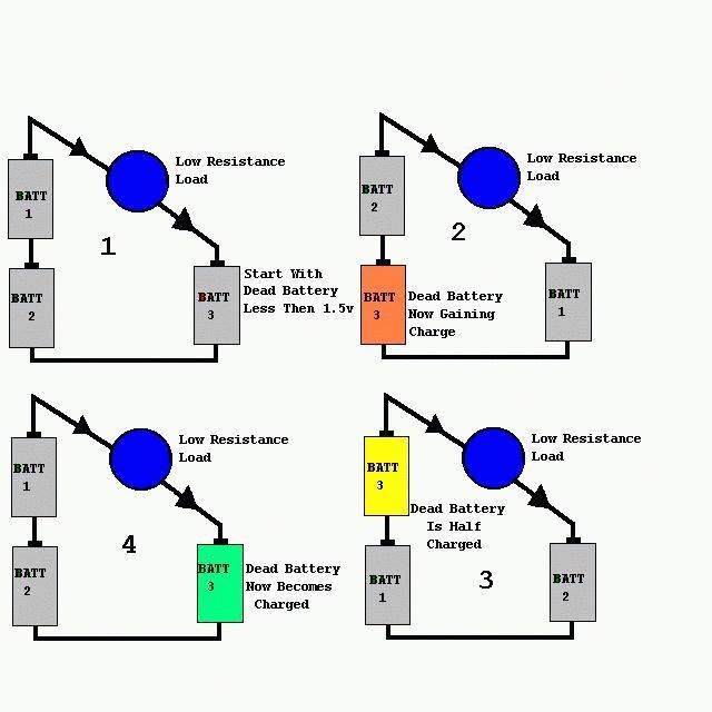
Important: Delayed Conduction in Bucking Coils

  • Topic Is Sticky
  • Topic Is Locked
  • 16K Views
  • Last Post 24 February 2024
Chris posted this 11 March 2019

My Friends,

The Effects of Delayed Conduction in Bucking Coils is important. What is Delayed Conduction? What is the point of this?

Delayed Conduction is specifically to get the Voltage on the Terminals of your Partnered Output Coils as high as possible in reason! Its the change in Magnetic Field that Creates Voltage, its the Opposition of Magnetic Fields that Pumps Current! 

Circuitry can also be employed to delay Conduction on the second Partnered Output Coil.

Ref: How to build your own Above Unity Machine


I gave an example of Delayed Conduction here.

As you can see, the Mosfets will only conduct when the Zener Diodes Conduct, this is rated to 18 Volts.

This means, the ends of the Partnered Output Coils must be at least 18 Volts, before the Coils can power any load!

We have seen this before! This is not new to those that have done the Study!


The MEG Demo Circuit

Where D2 represents a Bi-Directional TVS.


Ref: JLN MEG Replication


Ref: The MEG Team Data.

Where the Top Trace represents the Input Channels, and the bottom Trace Magnetic Resonance in the Output Coils, seen as Asymmetrical Regauging.


NOTE: JLN used a MOV in his MEG Replication. A MOV has similar Voltage to Current Characteristics! 


Ref: JonRB


Ref: Renesas Datasheet


Ref: The MOV or Varistor V I Characteristics


I want to stress the point of getting the Voltage on the Terminals of your Partnered Output Coils to a maximum without being disturbed. Input Creates a Voltage on your Terminals, then the Input is switched off. Then your Partnered Output Coils Conduct and we Pump Current.

Remember: Some of these Circuits may require an Earth Ground.

   Chris

Order By: Standard | Newest | Votes
Chris posted this 11 March 2019

My Friends,

What I am sharing is critical, extremely important Information!

Magnetic Resonance is seen at a specific Frequency and a specific Duty Cycle. This is a specific characteristic of the Coils, Induction and so on. Lots of turns means low Frequency, few turns means higher Frequency.

When you catch the Wave, you will know, trust me!

Monitor your Currents, you will see, equal and opposite. You will see the Sawtooth Wave form also, seen above and shown many times on this forum!

Bucking Coils, Pumping Current, the effects of Magnetic Resonance are truly amazing. Brute Force for free, a little tickle under the chin and the Machine does the rest for you, a Pump, like the Hydraulic Ram Pump, shown many times also!

Simple Starting Circuit - Some parts upside down to make you think backwards.

Where: D1 is a Delayed Conduction Device, Zener Diode and a Mosfet or a MOV or a TVS or similar device.


I really want to encourage all here to share your work, this works!

This is very important! A critical point has been reached and I need all members here to direct their attention to this topic for a little while?

Please?

We truly are Light Years ahead of the other forums!

   Chris

Wistiti posted this 12 March 2019

I will build something base on this concept you share my freind and will share it with all on the forum.

For now my spare time is limited but as soon as I can, I will prioritize this one.

Thank you for sharing!

Chris posted this 12 March 2019

My Friends,

@Wistiti - Thank you my Friend.

What to look for is, at the time of Delayed Conduction, is a Standing Wave of much Greater Potential:

Ref: https://youtu.be /cQWLP6k-c7I


A Naturally Simulated Effect, one in which we need to simulate in our Electromagnetic Waves! This causes the increase in Magnetic Resonance, it can be much greater than the original Wave input! Then of Course, we hold Conduction, the Wave dissipates and we have much greater Energy Output than we input!

This is the: Waves Slapping Together.


We saw an example of how this can work here.

   Chris 

Chris posted this 12 March 2019

My Friends,

On the: 30 July 2017, I placed the thread: Timing, here for a reason. I made specific focus on the interactions of the Coils and how the Coils were used in specific ways, to reduce Transients, in the form of Common Mode Noise, almost entirely!

I asked you to think about ways to reverse the situation, saying: "You need to let the System Breath, bring it to life!", now, today, I have shown you how important timing is! What is possible with timed Electromagnetic Wave Interactions!

I ask you, do you see a pattern? Do you see what I am doing? Do you see how much planning and work this has taken?

Aboveunity.com has changed the world! We are light years ahead of the other forums! They have been left in the dust! Redundant, effective immediately!

We have made the world a better place, and we don't plan to stop here! Support us, help us, this train ride has only just begun!

   Chris

Jagau posted this 12 March 2019

Hi Chris

I noted that there was in addition to frequency and duty cycle a third extremely critical adjustment,

the power level of the mosfet gate,  for my circuit this has completely change the results.


I do not know if for others you have noted the same results ??

Jagau

Chris posted this 12 March 2019

Hi Jagau,

My Friend, yes, there is a little fiddling. Once found the results are very prominent. Its not hard to miss once one knows what to look for! Problem is, very few know what to look for!

Yes you're right, slowly turning up the input power and one will soon find the Conduction Power required. wink

Fantastic work my Friend!

   Chris

Chris posted this 13 March 2019

My Friends,

I want to share again:


The same rules apply as I have shared in the thread: Parallel Wire or Bifilar Coil Experiment which was a very important introductory thread!

If you learn and understand what I am trying to share in the video, then catching the wave will be the only thing that takes a little fiddling!

   Chris


P.S: This content I am sharing with you, you will not find anywhere else in such detail. I ask you, save and share this information. It is very important!

Jagau posted this 14 March 2019

 Its the change in Magnetic Field that Creates Voltage,

its the Opposition of Magnetic Fields that Pumps Current

Hi Chris 

This is words of wisdom too

Jagau

Chris posted this 14 March 2019

My Friends,

This thread is so important!

I would like to emphasize the necessity of catching the wave. We have seen four examples of this:

I have shared one of my experiments also: Here

My Friends, I really want to stress the importance of patterns!

  • All of the above have one thing in common, the threads have the tag: Above Unity
  • All of then showed the Sawtooth Waveform!
  • All of them had very clear Energy Gains using Magnetic Resonance.


The Sawtooth Waveform

We all should be very familiar with the Sawtooth Wave form! I have been showing it for months now. It is very important that the understanding of how this waveform is achieved! Like I have tried to explain, this is where the Waves Slap Together, the Electromagnetic Fields of each Partnered Output Coil.


The Partnered Output Coils react together to Generate Energy. Using Delayed Conduction to achieve a Resonance in the Coils, called Magnetic Resonance!


Don Smith:


The MEG Team:


Tinman (Bradley Richard Atherton):


Graham Gunderson:


The Sharp Spike is Delayed Conduction, it is where the Two Partnered Output Coils have Magnetic Interactions that slap together very fast!

It causes a high Voltage, we hold the Conduction and the Magnetic Fields decrease linearly:


The Magnetic Fields slowly decrease to Zero, Equilibrium.


If you do these experiments, and have the patience to work together with us to the end goal, then you truly will have a self running Energy Machine!


@Jagau - I am glad that helps!

The fundamental magnets have been broken free of their binding forces which constrained them to be steady-state single pole uniform magnetic flux devices. They are now able to simply support mass, as demonstrated with the transformer steel illustration. They can now easily be made to adopt a dynamic motional field by applying a tiny amount of excitation. Specifically, 10V @ 1 mA (10 mW) of excitation at 60 Hz. will enable the coils of the triode to receive from the Dirac Sea in excess of 5000 watts of usable negative energy; how much more can safely be removed has not yet been determined.

Ref: Nothing is Something


Jagau, the above quote is nothing about the Magnets! Its about the Magnetic Fields! It reads wrong, there is an effort there to deceive, to miss-lead others!

The dynamic Field is Magnetic Resonance between the two Coils, actually Floyd Sweet used two sets of two Coils. Yes it is excited by a small amount of Power, because at Magnetic Resonance, the Coils feed back Energy to the input.

How this should read:

The fundamental magnetic fields of the Coils have been broken free of their bound force which constrained them to be steady-state single pole uniform magnetic flux source. They are now able to simply support mass, as demonstrated with the supporting Current demonstration. They can now easily be made to adopt a dynamic motional field by applying a tiny amount of excitation. Specifically, 10V @ 1 mA (10 mW) of excitation at 60 Hz. will enable the coils of the triode to receive from the Dirac Sea in excess of 5000 watts of usable negative energy; how much more can safely be removed has not yet been determined.


By changing only a few words, its now got a hugely different meaning!

   Chris

Chris posted this 15 March 2019

Hey CD,

I agree, yes there is an element description!

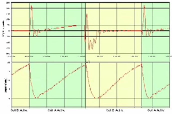
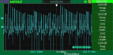
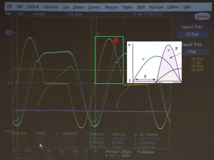
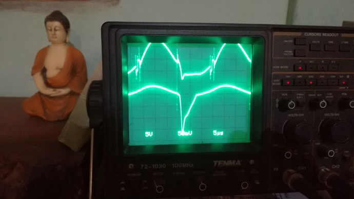
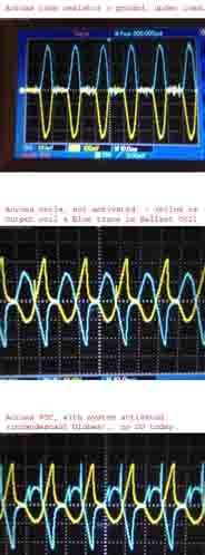
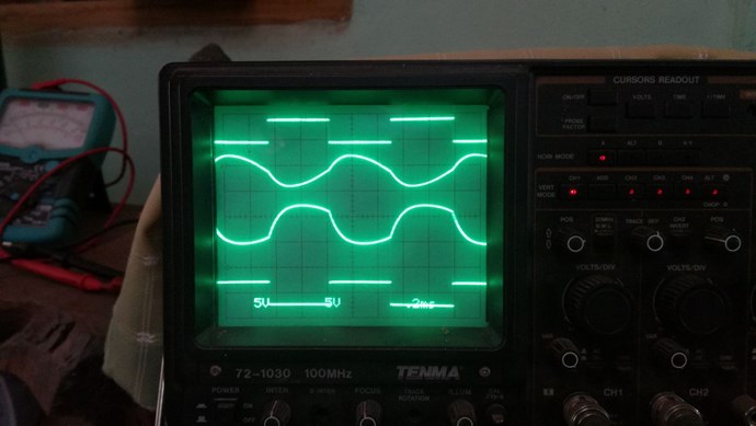
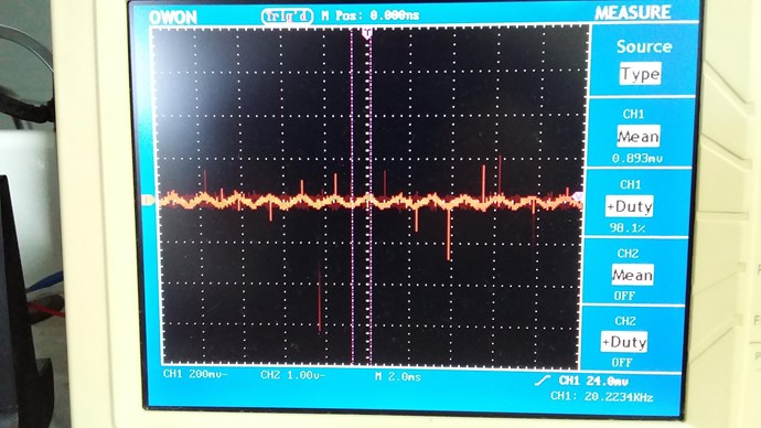
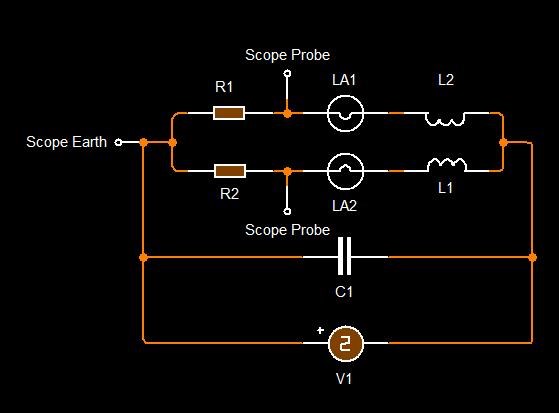
I am not convinced Graham's MIT was in Saturation. I think maybe close, but the problem I see is, if he was in Saturation, the Voltage and Current Waveforms would not be 90 Degrees from each other:


Input Voltage ( Yellow ) and Input Current ( Blue ) would be almost in phase, not a quarter Cycle later. A Quarter Cycle is 90 Degrees and indicated the Core is not Saturated.


So, at Saturation, Inductance is lost, and an LC Resonance Tank Circuit can not be 90 degrees out of phase. The Inductor becomes a Resistive Element, because it has lost all its Inductance L.

Sorry, long winded, but my analysis, is that he is not in Saturation, but is close. I may be wrong and over looked something?

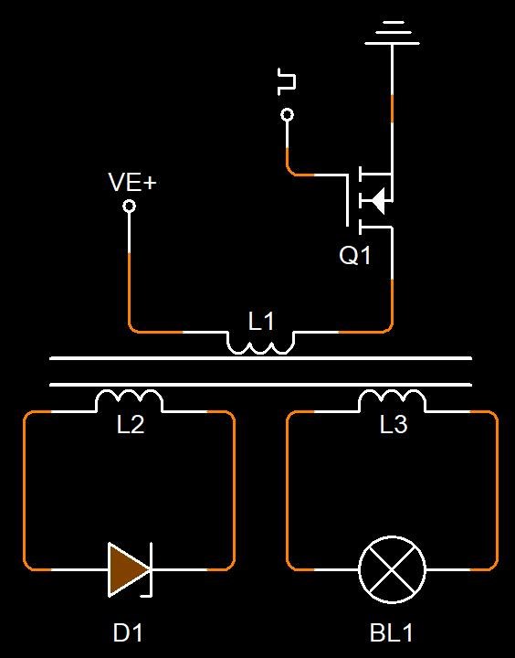
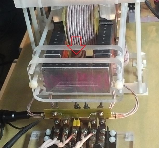
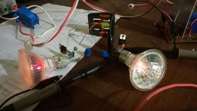
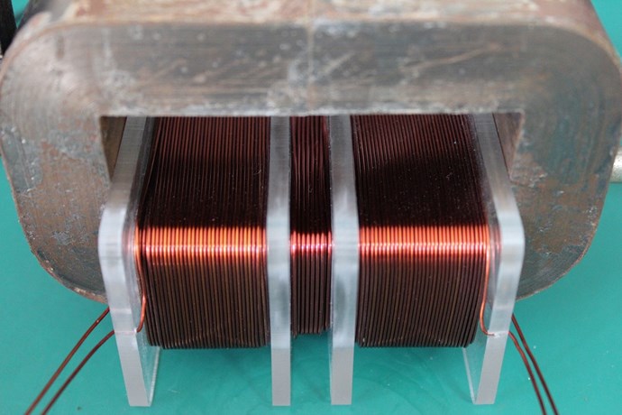
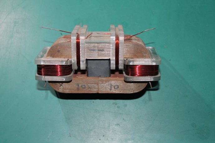
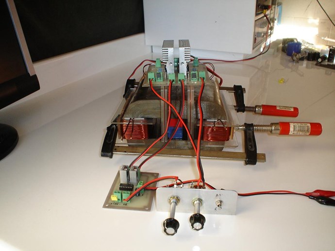
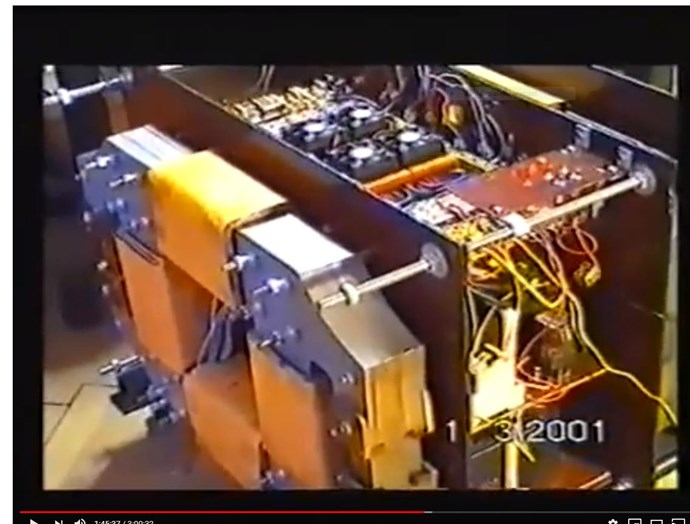
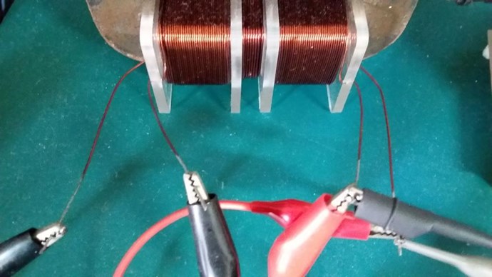
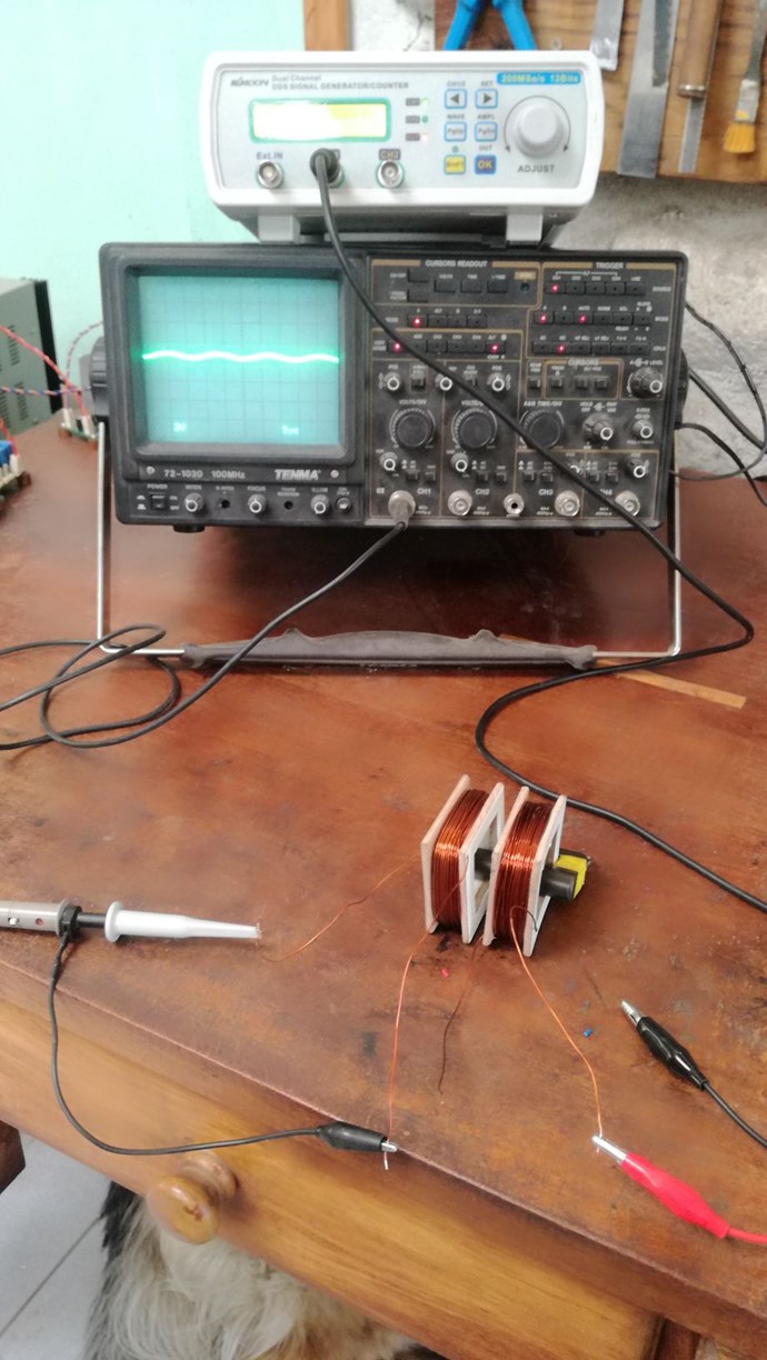
Graham has an interesting machine, yes it is directly related to this topic! But it is done in a slightly different way.

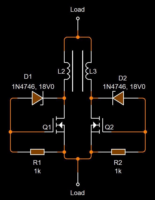
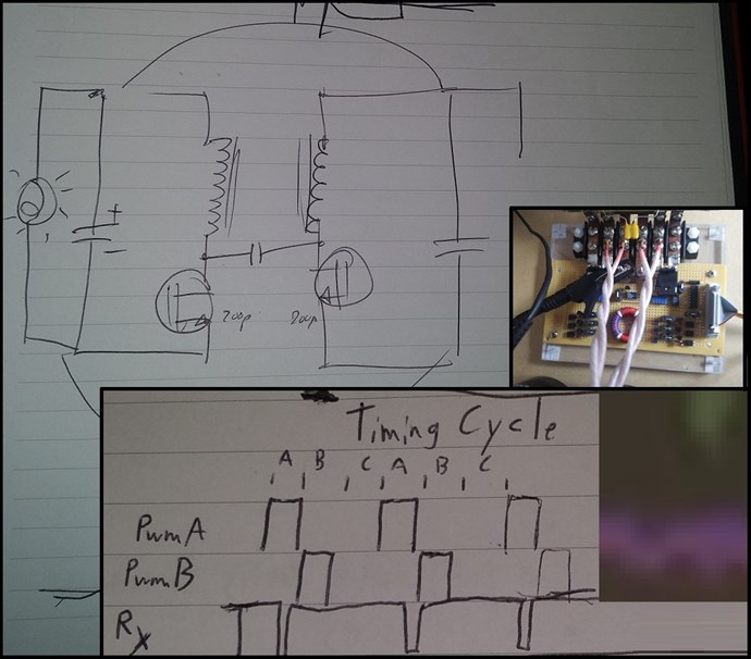
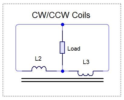
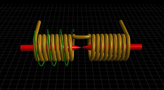
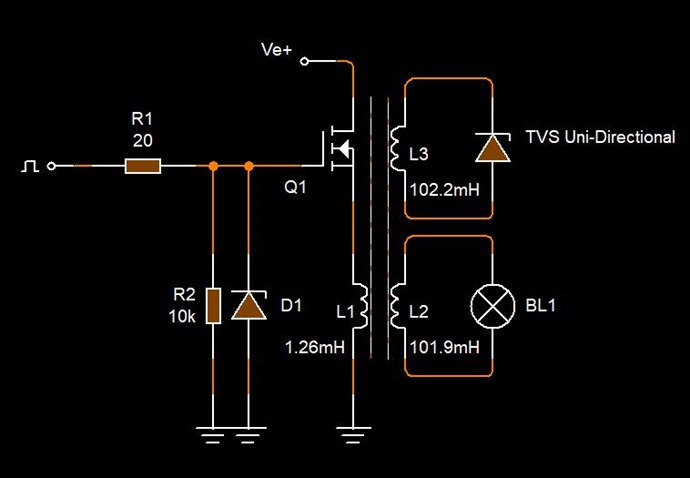
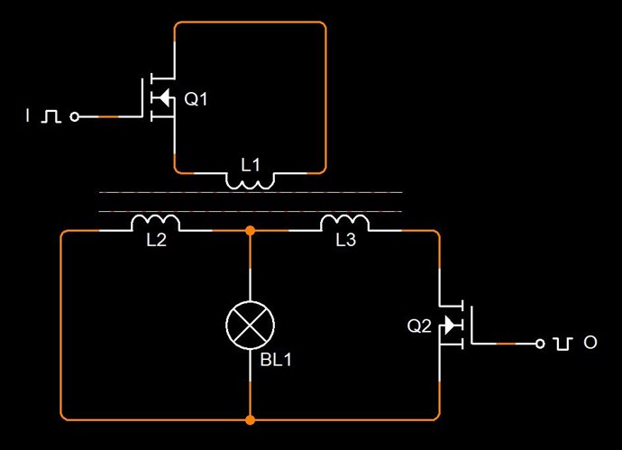
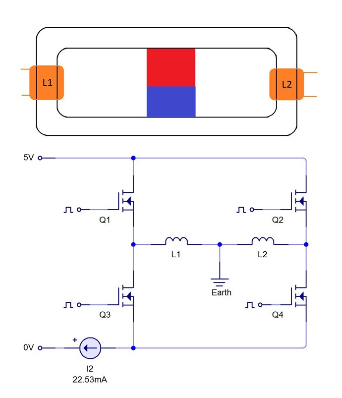
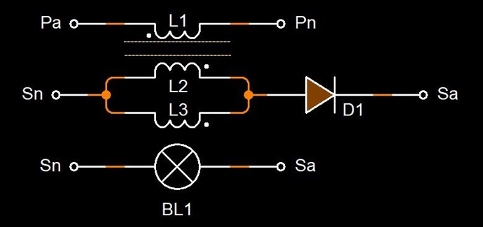
Grahams Partnered Output Coils, should be thought of as two Parallel Wires! Connected in Parallel Series! The Wires have a direct relationship to each other! At anytime the Relationship to each other were to change, so would the Magnetic Fields between them.

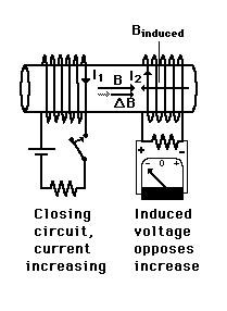
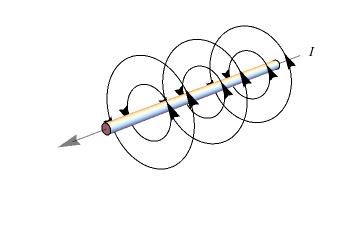
Remember, Current is the Magnetic Field!

If the Current between the two Parallel Wires, were to be aloud to change, then there would be a full reversal, which we have seen already. Why a full reversal in Current? Because it must be Equal and Opposite, Faradays Law of Induction with Lenz's Law states this!

This Change, only requires a change is the flow of Current, which is a Conduction related issue!

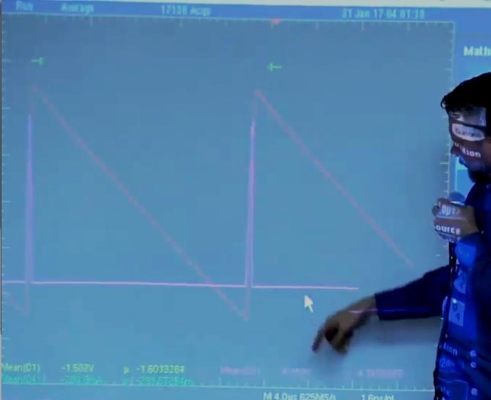
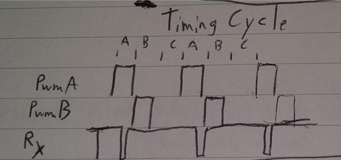
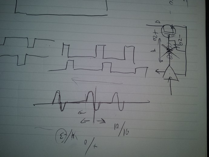
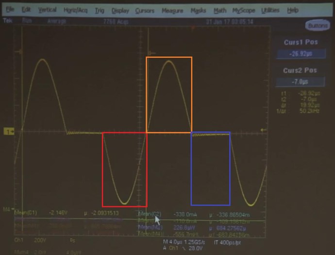
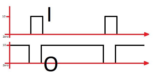
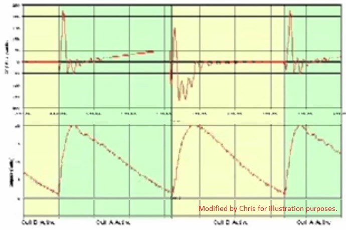
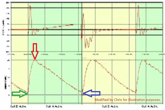
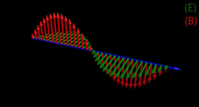
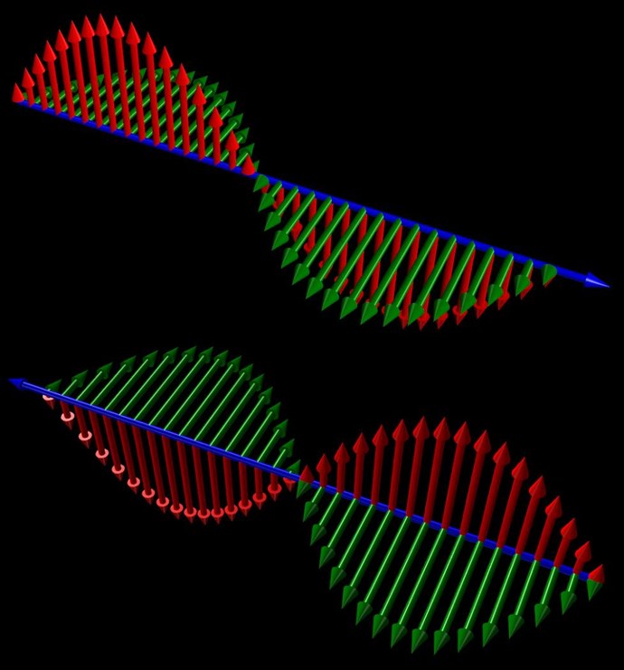
Break up all the parts of the Cycles seen:


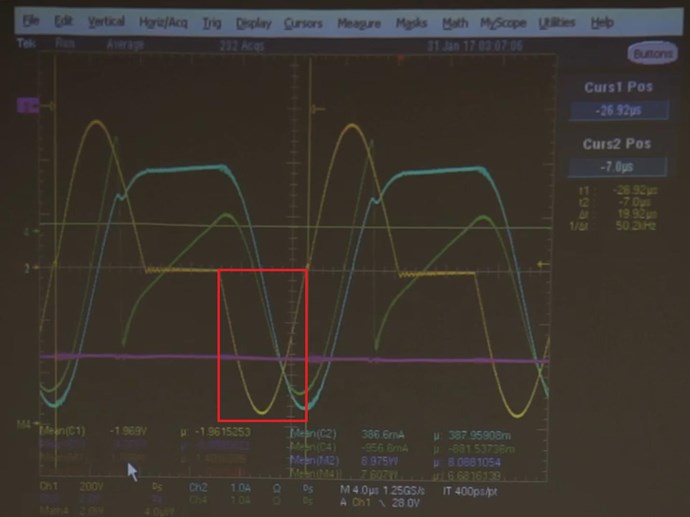
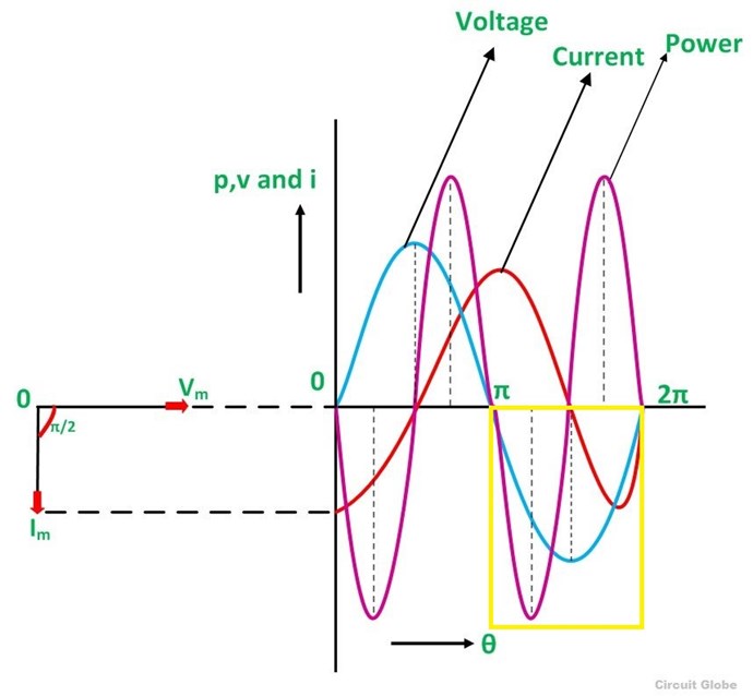
The Area marked in Red is standard Transformer Induction, there is no indication of any overly unusual activity in this region. This region is the Half Cycle, it could be thought of as a negative DC half of the AC Cycle. Power here from Input to Output is Transformer Induction, with losses. The power would look like this:


Marked in Yellow.

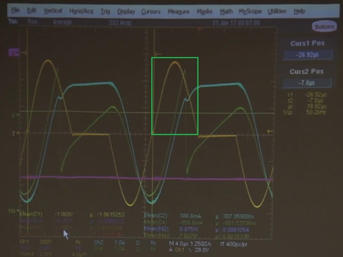
Now, marked in Green, the active part of the Action comes:


The power would normally look like this:


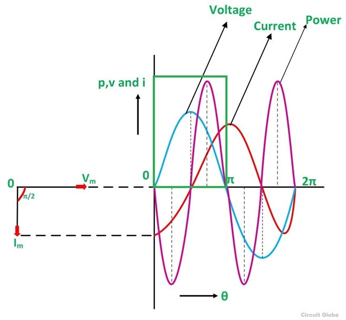
Marked in Green. Now we must carefully analyze this, because we only have half of the Power expected, we have a specifically arranged interruption in Conduction at Peak Current, or very close to it.
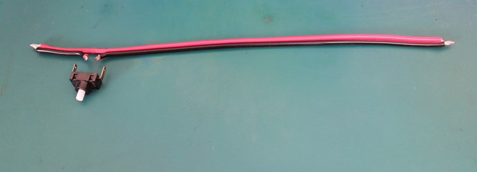
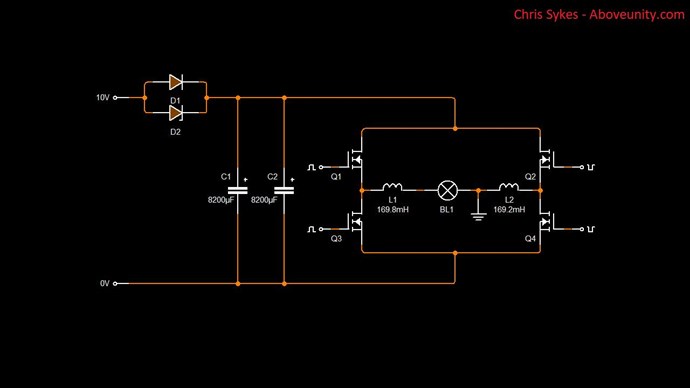
 

The Switch:

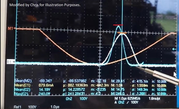
Important: The Green Trace is the Output Current shown on only One wire:


At the point of the switch:


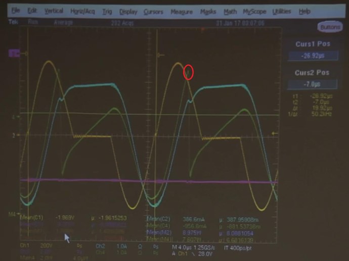
Marked in Red, the point of the Switch! Also seen, and should be noted, the only kick in the waves seen:


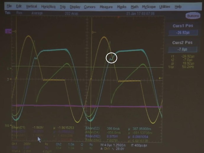
Marked in White, the only kick in the waves seen. Its a negative Kick, a kick that shows a negative pressure on the Input Current ( Blue ). Also important: The Input Current, after the Switch, the amplitude increases over time!


So, what's going on?

  1. Parallel Output Wires are building in Voltage and Current, the are fully loaded up until the Switch!
  2. At or close to Peak Current, the Parallel Series Connected Coils are Interrupted, the Conduction on One Coil is Broken...
  3. What happens now? How can the Current Flip so quickly?


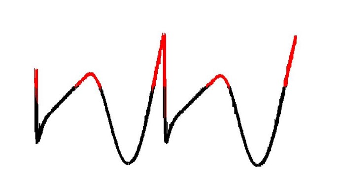
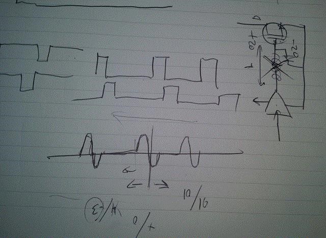
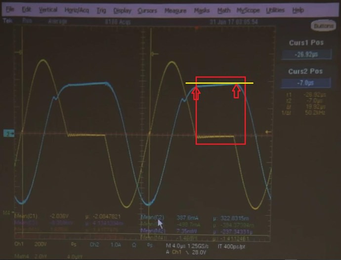
The Green Trace above, shown above to indicate the Positive ( Red ) and Negative ( Black ) swings in the Output Current Trace.

Seen in the middle, is the very sharp change from Positive ( Red ) to Negative ( Black ). This happens in a very short time!

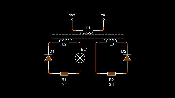
The Coils have a Tension, then the Tension in one Coil is broken, via a switch. One Coil still has a tension, but the other has no current, but the other coil wants to change. The Tension in this coil can not stay where it is.

The Coil that has a broken tension, is conductive via the Mosfet's Internal Diode, but only in reverse. We know that Equal and Opposite Currents must start to flow if there is a Conduction Path! 

Question, does the Switch need to be turned back on? If so why?

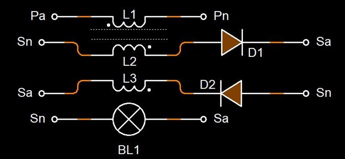
Graham is using the Tension ( Voltage and Current ) on one Output Coil, to Flip the other Output Coils Polarity, to create equal and opposite Tension ( Voltage and Current ). Bucking Coils! He is using Partnered Output Coils!

Well, we have a reasonable post, nearly out of words...

   Chris


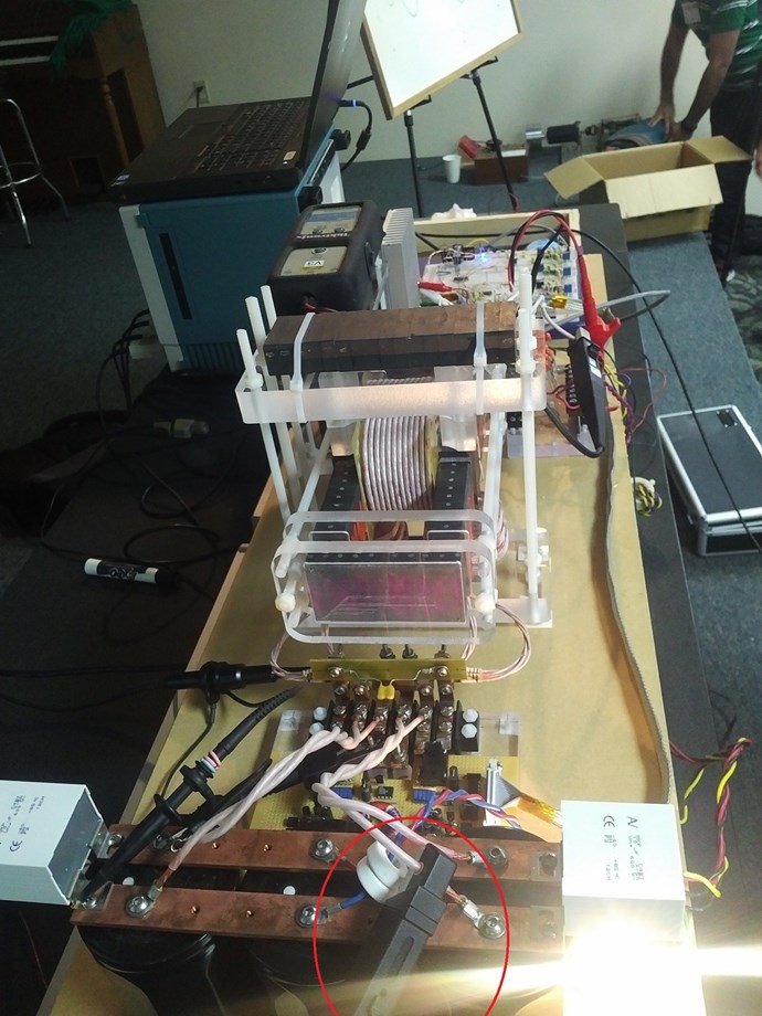
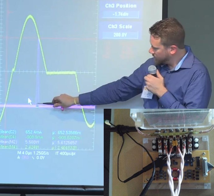
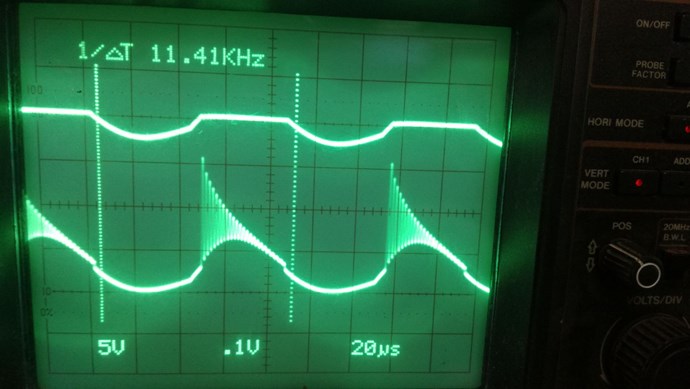
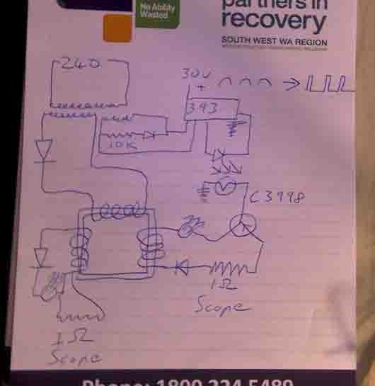
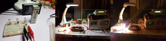
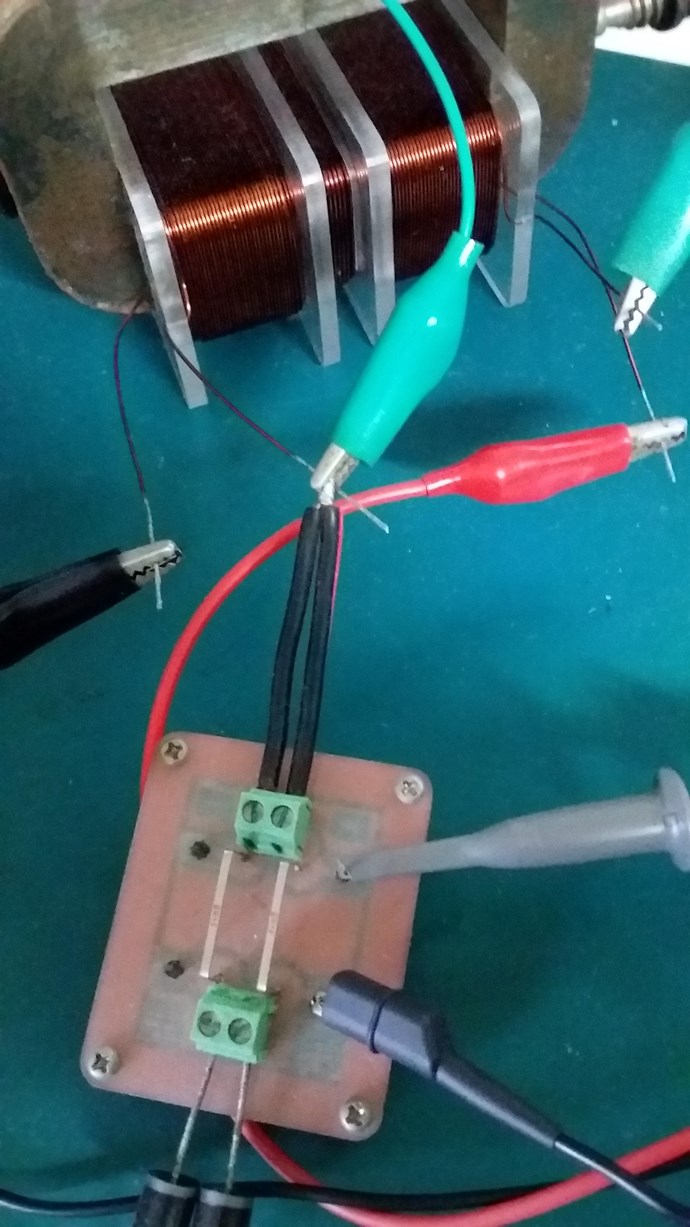
P.S: Bad images, sorry, I tried to find the best I could but they are not very good for what I am trying to show.

Jagau posted this 16 March 2019

Very good analysis Chris

As can be seen everything happens when the little kick occurs, the output current (green) is then ahead of the input.

 This happens when both current go through the most negative point.

Perhaps this is due to the timing of the 2 mosfets, there must be this special timing

that makes one of the two resumes the pendulum to project the ball further? An analogy of the swing?

as if it would be the capacitor who would take the lead

jagau

Chris posted this 16 March 2019

Thanks Jagau,

I posted another post also, a second one, but deleted it because I was not happy with it. Third party Circuit analysis is not my strong point, and I only want to post what I am pretty confident about.

Part of my post was about the "timing of the two mosfets" you point out. But I am confident my last approach will confuse others and make this harder to grasp.

One day, I believe, we will grasp so much more, Just Voltage and Just Current, the relationships of them, I believe is a small part of the Story.


Let me try again:


My Friends,

In the Terminals of the Left Partnered Output Coil:


Using the High Voltage Probe across the Left Partnered Output Coils Terminals, shown above, gives this Waveform:


Conduction is Broken for a very short time! Graham said around One Millionth of a second in the video? We have seen the Flip in Output Current on the Output from the Right side Partnered Output Coil:


The Same Time Base is used on the Scope. Note: M = 4μs

I guess, what I am trying to show here, is the Delay in Conduction of Graham Gunderson's Partnered Output Coils! His has done very much more like we saw here. The MEG, a  little different, I showed a slightly different way again here.

At the end of the day, its all a Delay in Conduction all achieving the same end result: Magnetic Resonance.

   Chris

Chris posted this 18 March 2019

My Friends,

Delayed Conduction is a very easy way to control the Partnered Output Coils, sensitive to Electric Fields at Time t.

You will notice, The Partnered Output Coils Delayed Conduction Stage is always at a single point:


In the Area of Power if Voltage and Current are 90 degrees out of Phase, Current Lagging, is a very important place to keep in mind! All machines I have studied have used this area in one fashion or another, Kapandze, the Spark fires at the peak of the Wave, same place. Through a short thick Copper Coil. This interruption in Conduction, Delayed Conduction, is critical.

This Thread shows some circuits, but there is a little fiddling with what actually works. Frequency, Amplitude, Timing, but, the most important thing is: You know now, what to look for!

   Chris

Chris posted this 18 March 2019

My Friends,

For the GOOD in the World!

I want to let you ponder something. Its an important ponderance! Especially in this situation! The Time Bases are all the same:


Graham Gunderson's Left Side Partnered Output Coil was connected permanently to the Load, Capacitors and Globe:


For the entire time, between the Red markers! The Red markers indicate Off Time! Thus the Voltage Spike! Almost 700 volts. The Bottom Purple Line between the Red markers, is 9 Volts on the Capacitors, Conduction, Connected to the Output!

Connection interruption also seen here:


A big pixelated mess, but it can ne seen!

@CD - You asked, I wanted to point out, some huge things there for the ones that can see the coming problems!

Question: How did Graham make the Right Side Partnered Output Coil always show the same polarity flip in Current? Why does the Current not Flip the other way sporadically?

   Chris

Chris posted this 18 March 2019

My Friends,

A little speculation with a little evidence:

I believe Graham Gunderson was using Step Switching on the Partnered Output Coils - What Do I Mean?

Two Output Coils, Two Mosfets on the Output. One Mosfet for Each Coil.

In the closeup I showed:


We see evidence for something which Graham did draw for Reiyuki, who kindly shared all his images. He was present at the conference and took lots of fantastic Images while there, he also asked Graham lots of questions. One Image is shown:


With another Image verifying this image:


My Question:

Question: How did Graham make the Right Side Partnered Output Coil always show the same polarity flip in Current? Why does the Current not Flip the other way sporadically?


This is achieved by Step Switching the Output Mosfets as I have just shown. You will only find this information here! Other forums have tied this timing to the Input.

   Chris

Jagau posted this 18 March 2019

Hello Chris
I was away the last 3 days.
I take the time to study where we are.
This is a very interesting subject.
Jagau

Chris posted this 18 March 2019

My Friends,

@Jagau - Hope you had a good time! It is an interesting subject!

@All:

It is worth noting, The MEG has this exact same Process, One Coil Conducts, then the other, Slapping Together. The setup I showed you also. This process is simply How Hard and How Fast the Waves can Slap Together:


Thus the title of this Thread: Delayed Conduction in Bucking Coils.

There is a pattern, and the pattern is always the same, the Partnered Output Coils must Buck, the Coils must be made to Buck, normally they would not as shown in the thread: Parallel Wire or Bifilar Coil Experiment, and the Currents are always equal and opposite! Methods to make this occur can vary as we have seen on this thread!

No other forum on the internet, as far as I am aware, shows you any of these techniques! This information is new, especially in such detail! Some, a select few, I believe, have known about this for a long time.

   Chris

Jagau posted this 18 March 2019

Just a Chris question before going any further.
Is this scheme provided by Gunderson?


If yes this schema on the right is an IGBT not a mosfet.
And again the reverse diode is when the voltage goes from + to - is to increase the closing speed of the IGBT (+20 to -20 volts)

i mean diode between gate and emitter of IGBT
Jagau

Chris posted this 18 March 2019

Hey Jagau,

Apparently drawn by Graham at the Conference for Reiyuki. 

Graham drew the same diagram here:


He used the term Mosfet in the video.

Hope this helps some.

   Chris

Jagau posted this 18 March 2019

Thank you Chris for the correction it is a mosfet no doubt.

It draws the intrinsic capacity of the mosfet so as to understand how the gate fires in relation to the source.
Moreover, he draws the intrinsic diode of the mosfet in a way that I did not know.

We learn every day.


And in addition it gives a little key design not heatink and when you listen well it's the key.


Jagau

Chris posted this 19 March 2019

Hey Jagau,

Isn't it silly how many symbols we have for the same thing:


MOSFET - Metal Oxide Semiconductor Field Effect Transistor

Ref: www.electronics-notes.com


I agree, if we don't learn something every day then perhaps the day has been wasted?

   Chris

Jagau posted this 19 March 2019

Certainly Chris, that's why there is so much confusion in terms of the interpretations,

but most of the time when we look at the manufacturer's dasasheet,

it's the first two on top of the other that we see in datasheet


In addition the IGBT symbol looks like this


Even more confusion with mosfet.


Jagau

Chris posted this 19 March 2019

My Friends,

To re-cap:

The Partnered Output Coils have three things all going on in time:

  1. A High Energy Field is created around the Coils: Shown as Power P.
  2. There is a timed Disconnect and Re-connect: Delayed Conduction.
  3. The Coils Fields ( Currents ) React in such a way to Slap Together very fast.


We have enough evidence above to say this is exactly how the Output was achieved! Don't forget the Wave:


This is what's going on between the Partnered Output Coils:


The Question is: Are all other devices working on the same principles?

The answer is: Yes, almost exactly the same!

   Chris

Jagau posted this 20 March 2019

It seems that the Synchronous rectification is very important for Mr Gunderson
This image is worth a thousand 

especially that of the center

Jagau


Chris posted this 21 March 2019

My Friends,

Don't forget, the waveforms seen have no Vin.

All this is done with the Partnered Output Coils Vout and Iout.

Vout is "Generated", pumped, or supporting Mass, is: Iout.

What you see, is entirely an effect of the Partnered Output Coils. Conduction, Magnetic Fields, Interactions.

This Thread is SO Important, those that have followed will fully understand this Action!

   Chris


P.S: The image can be found with the article: Synchronous Switching Regulators.

Jagau posted this 21 March 2019

This subject is very important as Chris says.


It helps me understand important effects to seize to reach the aboveunity
I think that '' Synchronous Switching Regulators '' is one of the means that Mr Gunderson has taken to achieve his goal but as he says in his video he uses it in another way and that is why he uses the mosfet without heatsink think about that

The most important is the following:

What you see, is entirely an effect of the Partnered Output Coils. Conduction, Magnetic Fields, Interactions.


Jagau

Chris posted this 21 March 2019

Hey CD,

Excellent Experiment!

One half of the AC Sine wave can be seen as a half DC Wave, we use linear rectification units to achieve this from an AC Sine Source. We saw this here.

We must think of this DC half Sinusoidal wave as a pressure, or a Potential, or a bucket of water, the higher the Amplitude, the more the bucket is full!

The Partnered Output Coils require the same pressure, but this can not be achieved when there is no pressure to begin with!

Imagine: A Submarine, at the Surface its strong, sturdy, rigid! Go to 2000 meters, its ok, sturdy, go to 10,000 meters things start to creak and groan, and things get pretty scary especially if one hits rocks or something!

We must start from a positive pressure first, this is the Half AC, or DC sinusoidal wave form.

The more the bucket is full, the deeper a Diver can dive into the bucket. The more Pressure the Coils are exposed to, the Harder the Slap together they will have when the Linear Rectification Units time the Conductive Kick.

A Timed connection of the Partnered Output Coils is the Key! Grahams is shown above. Others, do not require this complexity, shown in the first post.

The Conductive Kick is the Waves Slapping together! Like this:


Above is the reason I said to go up close to saturation but not at saturation.

This Effect all happens as the Coils are suddenly connected ( Conduction ), at the right time, One Coil Conducts, then a split second later the other Coil Conducts. Delayed Conduction.

I hope this makes sense!

   Chris

  • Liked by
  • Wistiti
  • cd_sharp
Vidura posted this 22 March 2019

Hi all, I would like to share some thoughts about the MIT in context with the thread. Please correct when I'm mistaken. I have been curious about the input signal shape, and concluded that the zero voltage section have a good reason, as it overlaps with the moment of interaction of the POC, the triangular output current waveform which is negative in this case. So the input voltage is switched to zero while the POC are inducing power, in order to not to load the input.IMO the input could be switched off earlier simultaneously with the interruption of the output coil, when the kick occurred. The input current will continue to flow during this part of the cycle, due to inductance or the primary(the resonant tank circuit?) which would be not of concern as no power is consumed at zero voltage. The input section is still not at all clear for me, at what points are the probes for Voltage and current.

  • Liked by
  • cd_sharp
  • Chris
Chris posted this 22 March 2019

My Friends,

Some Insight:


I hope this helps some!

   Chris

  • Liked by
  • mrblobby
  • cd_sharp
Chris posted this 22 March 2019

@Vidura,

I shared the images I received MIT - Graham Gunderson.

My Video above may answer some of your questions, if not please let me know.

Input Measurements:


Output Measurements:


I hope this helps!

   Chris

  • Liked by
  • Vidura
Vidura posted this 22 March 2019

Hey Chris, I understood the critical points of operation, My question is more about a detail of design of the MIT: How we can mantain the input voltage in a resonant tank citcuit at zero volt during part of the periode without damping the oscillation? 

Vidura.

  • Liked by
  • Chris
Chris posted this 22 March 2019

Hey Vidura,

The Input is a measure of Load vs feed back.

For example, take a Transformer, measure with no load, then measure again with a load. Very different measurements! Phase angle especially will be very different depending how much one loads the transformer.

The Input is chopped DC, 50% duty cycle, from the H-Bridge: ( Top Waveform )


I like Cap Inductor in series, not so much in parallel. Not sure why, Parallel just feels wrong. The Input is assisted by the output, I have shown this before. Self Assisted Oscillation in a Shorted Coil - Bucking Magnetic Field Oscillation


That was way back in 2011. The Output assists the Input, one Coil works with the Input, remember we have three coils. There is no damping, there is an Assist.

See this video for a little more info: @ 4:05


A Positive Feed Back to the input.

So: 1 + -1 + 1 = 1 where as we would normally see: 1 + -1 = 0 nothing left over, all the Input Is consumed!

   Chris

  • Liked by
  • mrblobby
  • Marathonman
Vidura posted this 22 March 2019

So the input signal section at zero voltage is due to the feedback from the POC, I got it , at least I think so. And I remembered that when Graham was asked about the operating frequency he pointed out that it was not at 50%duty, but something like 33.3%positive, 33.3%negative and 33.3%off. Otherwise at 50% duty square input this special wave shape would not likely resonate.

  • Liked by
  • Chris
  • Marathonman
Chris posted this 22 March 2019

Hey Vidura,

Yes you're right. 33% is divided up like so:


So we see, 33% each:

  • Red
  • Orange
  • Blue

Of course, a normal H-Bridge is 50% to get an RLC Tank Circuit to resonate. Graham Gunderson's MIT is a special case requiring Off Time, this Off Time just happens to be 1/3rd of the Cycle.

Where we see Off Time, we see an increase in Current amplitude:


Of course, this is a significant indicator that the Output Coils are feeding back Energy to the Input. Feed Back as Floyd Sweet told us.

There is so much information in these scope shots, much I have covered here that you will not find on other forums! We truly are Light Years Ahead of the other Forums!

   Chris

Chris posted this 23 March 2019

My Friends,

Some more information:


I hope this helps!

   Chris

  • Liked by
  • Vidura
Chris posted this 23 March 2019

Looks like I just broke YouTube:


   Chris

  • Liked by
  • Vasile
  • cd_sharp
Chris posted this 24 March 2019

My Friends,

A little more Information on Delayed Conduction:


I hope this helps some!

   Chris

Jagau posted this 24 March 2019

Hey Chris


One of the best video that I saw on the site of Aboveunity.com
I would give 3 times I like it
We are close to the goal.


jagau

  • Liked by
  • Wistiti
  • Chris
Wistiti posted this 24 March 2019

Agree with Jagau. Excellent explanation my freind!

Thank you for your time and effort. 😊

  • Liked by
  • Chris
Chris posted this 24 March 2019

Thank You my Friends wink

I try, every day to add useful content, to make a real difference in the world!

Don't forget, this is not the only way! A simple Light Dimmer Circuit can also give you the same results:


Of course, this Circuit is Bi-Directional. Also, importantly, you can adjust the timing of Conduction in Time t.

I pointed this out here.

I hope, most of you will be able to see a greater pattern emerging, of what I am doing. Things will be falling into place. Things making much more sense now.

A small story for you:

In the beginning, I had problems with the Coils. Using Coils as I have shown, with a Circuit Diagram like this:


Ref: Aloha's Post

Also shown in fig 2 in the above diagram, connected to a static Load, static meaning Conduction. 

The Problem I had was the Coils would mostly always have Currents in the same Direction. Lenz's Law always resulted between Primary and the Two Secondary's and I did not want this! It took me a long time, and I had to force myself to think simple, to understand the simple Laws of Conduction, Magnetics, and Time!

Most of the time, in this configuration, the Coils must always have Currents in Parallel and in Phase! The Currents will never change! We have covered this in detail in the thread: Parallel Wire or Bifilar Coil Experiment.

Drop Conduction on ONE of the Secondary Coils, however, for a split second, things can change very quickly!

NOTE: Other ways exist to achieve this result!

Some very simple, very basic experiments showed me that this is the key to making the System Asymmetrical, Lenz's Law was not effective back on the Primary. 

Some of my early experiments showed me this, but expanding this idea was somewhat of a task to grasp in full. I can not explain why this was...


I hope all here find this useful, it is a story of progress, and a lesson of simplicity! Breaking things down to the most basic level!

   Chris

  • Liked by
  • cd_sharp
Chris posted this 26 March 2019

My Friends,

Perhaps my last post was not as useful as the Videos. Another:


I hope this is useful!

  • Liked by
  • Jagau
  • Wistiti
Jagau posted this 26 March 2019

Thank you Chris

this video is very informative and you add something new for me

about a zener between gate a drain of mosfet?

jagau

  • Liked by
  • Chris
Vidura posted this 26 March 2019

Hey Chris and all following,

Finally back at my workshop i made a test with the proposed delay circuit with the mosfets and zehner diode.

I built this with 18v zehner diode but it resulted in fast selfoscillations of the switch like this:

And the current (upper trace) kept trunked off instead of the desired delay. When thinking about it is due that the gate voltage colapses immediately when the mosfet becomes conductive and recovers at high frequency. With a NPN transistor it might perform better, I will do a try. For the mosfet a stable gatedrive supply will be needed.

Regards VIDURA.

  • Liked by
  • Chris
Chris posted this 26 March 2019

Hey Vidura,

Awesome work! The Classic Sawtooth Waveform, which we should see! Look what you have achieved:


Ref: The RT V3 - Above-Unity


Almost the exact same basic waveform! Well done!

   Chris

Chris posted this 26 March 2019

My Friends,

Two other examples of Magnetic Resonance are:


We must realise, at Magnetic Resonance the machine creates a much larger Reaction, compared to the Action. I realise the Circuits and Input to Output Measurements are completely different, Jim Murrays not showing any above unity gains as far as I can tell, but the point is to look at the Effects!

   Chris

Chris posted this 27 March 2019

Hey Chris and all following,

Finally back at my workshop i made a test with the proposed delay circuit with the mosfets and zehner diode.

I built this with 18v zehner diode but it resulted in fast selfoscillations of the switch like this:

And the current (upper trace) kept trunked off instead of the desired delay. When thinking about it is due that the gate voltage colapses immediately when the mosfet becomes conductive and recovers at high frequency. With a NPN transistor it might perform better, I will do a try. For the mosfet a stable gatedrive supply will be needed.

Regards VIDURA.


@Vidura,


At all times the Voltage at the point of the Mosfet Drain, and the Cathode of the Zener Diode is greater than the rated Voltage, the Mosfet should be On. So the waveform may not be a true indication of Conductivity.


Some experiments with Inputs of a short pulse might be worth your while. Finding where the Zener is triggered and how long after the pulse the Ringing lasts.

Again, great work! This is a huge step forward! The Sawtooth wave is there, you have Nailed it! Nice!

   Chris


P.S: How many turns on your POCoils? I would look at increasing the Turns Increasing your Inductance and this should decrease your optimum Frequency and Input Voltage.

  • Liked by
  • Vidura
Vidura posted this 27 March 2019

Chris

I used a 40 mm EE ferrite with 13turns  CW- CCW ot the outer legs, ten turns primary on the inner leg, the first triggering seems to be at 18 volts  as the zener diode, but the current of the positive halve wave fails to flow. the voltage was measured across the load(12v incandescent lamp) and the mosfet. I have made a test with a 13007  transistor instead of the mosfet, the effect of delay could be observed, but not always, only at higher powerlevels and certain frequency, and the transistor heats considerable, the voltage rise higher to around 30volts. Anyway the TVS, Varistors, GDT devices and also the sparkgap have considerable losses as well, but the gain of magnetic resonance should be far greater.

later ill make a test with another coilset with more inductance to compare results.

Vidura.


  • Liked by
  • Chris
Chris posted this 27 March 2019

Hey Vidura,

Cool, ok, yes I would increase Output turns to 20 or 30 turns if possible, input to 8 turns.

Drop the input voltage.

Add a Zener Diode for Gate Protection, with a slightly higher break over voltage: D2


I hope this helps some!

   Chris


Jagau posted this 27 March 2019

hi

In trying to protect a mosfet against a high energy transient coming from the drain such as from a large inductive load, we connect one or sometimes two zener diode between the gate and source in order not to exceed maximum ratings for Vgs (e.g. +/- 20V) .

We know a zener diode is already between drain and source du to structure of the mosfet.

What we meet very rarely is if we add a zener is between the drain and gate, it will turn the mosfet on so the majority of the energy pass from drain source .

During off time of mosfet,  Vz will keep mosfet on and no delay conduction occur i think? Because of low Vz

Am trying to understand?

Jagau

  • Liked by
  • Chris
Chris posted this 27 March 2019

Hey Jagau,

Apologies, today has been busy.

I have corrected my mistake above.

Yes there is a reverse diode between the Drain and Source. The internal Mosfet protection Diode:


We are putting a Zener as a delayed Trigger from Mosfet Drain to Mosfet Gate. The Zener Diode Cathode is connected to the Mosfet Source, sensing the Voltage if you like. Yes I agree, there is a good requirement for a Gate protection Zener Diode.

I agree, and yes, the Mosfet should be off during the reverse bias from the coil.

I agree and from my simple experiments, not including capacitance of the Mosfet itself, the possible ringing of the arrangement, at high frequency, so, I suggest, stay at a low frequency.

Another Video:


I hope this is useful!

   Chris

  • Liked by
  • Jagau
  • Forelle
Chris posted this 27 March 2019

CD Awesome Work!

   Chris

Chris posted this 28 March 2019

Hey CD,

The Time required for the Zener Break Over Voltage is the only time you need Secondary Voltage, Induced from the Input, at the Cathode of the Zener and Drain of the Mosfet. Remember the Diagram shown, Asymmetrical Regauging:


We Regauge the System, short timed Input, enough for the System to reset and become able to do Work again. The Input is only required for a short time to start the machine off.

This means, any time the System has Input that is not doing anything, the Input is best turned off. Requiring Frequency adjustment and short Duty Cycle. This should decrease the Input to the minimum amount needed.

Apologies, this seems a bit too obvious. However a requirement to explain.

Getting the Mosfet to turn on and off properly requires a little work, getting enough Voltage and Current on the Specified Output Coil.

Perhaps we could start a Thread on this?

   Chris

  • Liked by
  • cd_sharp
Vidura posted this 29 March 2019

Here I post an additional test, I have modified the windings as per Chris' suggestion, primary on the central leg 12 turns, outer legs 36 turns each CW-CCW. Also I have modified the delayswitch as following. the idea is that the 100nf cap charges at the breakdown of the zener and keep the mosfet on until the voltage reverses and resets at the breakdown of the second zener(5.1V)

It seems to work, although the current on the negative halfwave is much smaller than the positive, but with some more adjustments it should work as expected.The setup with a resonant tankcircuit and halfbridge:

and the scopeshot:

Upper trace current, zero is at the second graticulate line from aboth, the voltage zeroline at the middle of the screen.


Chris posted this 29 March 2019

Hey Vidura,

Excellent Experiment! Nice!

For the moment, remove one of the Delayed Switch's, Just keep one in there. So a simple Circuit like so:


Where the Zener Diode ( D1 ) is a Delayed Conduction Switch. This setup will enable you to find the best Resonant Point of your Coils. When found, the machine will vibrate and hum like Crazy.

The Resonant Frequency might be low!

The Resonant Frequency may only require 10% or less duty Cycle!

The Input may only need to be 5 Volts.

   Chris 


P.S: The Mosfet will need a Pull Down Resistor in order to turn it off properly when it needs to.

P.P.S: I started a Mosfet Turn On and Off Thread here: On and Off, Conduction in a Mosfet

Vidura posted this 29 March 2019

Hey Chris, I will test this version of the circuit, one coil would be shortened by the timing device, quite interesting. Note that this switch only work properly with AC, as the reversal is needed to turn off the gate, I will post the results regarding this at the MOSFET switching thread later. Also I'm using an analogue oscillator with 50%duty fixed for the moment, although I started to build a new one with two phase pwm and analogue duty cycle timing, which will be more effective. For the moment I am using what I have at hand. regards Vidura

  • Liked by
  • Chris
Chris posted this 06 April 2019

My Friends,

I want to throw you a Ball...

Three Coils, as we have been looking at for some 9+ Years now. One Input Coil, two Output Coils, Partnered Output Coils seen here:


A Step Up Transformer to some people. But, we are not using this arrangement Symmetrically! We are using Asymmetrical Regauging, the Potential Gained, the Voltage Gained, a Dipole if you like. 


Every Coil will have a Potential Difference on the Coils, this is Faradays Law of Electromagnetic Induction. Time Rate of Change of the Magnetic Field.

If we use a TVS, a Transient Voltage Suppressor, which has a diagram like so:


A Very Simple Device, which looks like this in the real world:


The stripe above indicating a DC, or a single Polarity, Uni-Directional device, the TVS without a Stripe indicating an AC Device, or a Bi-Directional Device, can be used in both Polarity's.

  • So what would we do, how would we use this device?
  • What would this device do?
  • How does it work?


NOTE: An extra Diode may be required in reverse to the TVS.


We have a specific Pulse into the Mosfet, it is controlled specifically, we Push Input into the Core, it costs us a little, BUT, then we have a Controlled Switch, the TVS Conducts... The TVS becomes a Switch at the specific rated Voltage. A Switch...

Why do we need to have the TVS Conduct?

We must support the Current, as we now have a Potential on the Coils, as soon as the TVS Conducts, we have switched off our Input.

Remember the VI Curve above?

We have Conduction, at the point where we have VC the Clamping Voltage, the Conduction.

This means, we have one Coil Shorted. The Second Coil has a Maximum Magnetic Field, it must return to equilibrium, to Zero State, this action, of falling to Zero State is the Neo Magnet Falling through the Tube:


This creates the Triangle Wave we have seen:


Ref: The MEG Team Data.


Where the Top Trace represents the Input Channels, and the bottom Trace Magnetic Resonance in the Output Coils, seen as Asymmetrical Regauging.

Please remember the Name of this Thread: Delayed Conduction in Bucking Coils 

We are delaying the Conduction, enough to make MMF React back on itself, the second Output Coil. All we are doing is bringing up the Potential on the Terminals.

   Chris

Chris posted this 07 April 2019

My Friends,

A video to further explain the Importance of this thread:


I hope this helps!

   Chris

mrblobby posted this 07 April 2019

Absolutely love this series of videos you've been putting together Chris. I really appreciate all the time it must take to put them together. It really helps to explain more comprehensively the principles at work for people like myself. 2 thumbs up.

Jagau posted this 07 April 2019

Another great Chris video


I agree with you mrblobby


Jagau

  • Liked by
  • Chris
  • Vidura
Hopeful1 posted this 09 April 2019

Thank you Chris. A fantastic post. It has made  lot of things a lot clearer for me. I totally agree with mrblobby.

Tony

  • Liked by
  • Chris
Atti posted this 09 April 2019

Hey man.


Quiet enough. There are a lot of readers, but there are few experiments.
  Maybe I don't care anybody?

Do you care about some other than some?

With a few thoughts I break this silence.

It belongs to an older project, but now it was taken back.
I adapted it to MrPreva layout.

This is the secondary switch. The name is strange because the real secondary coupling is the two 220-volt bulb.

The theoretical drawing is shown here.

The base frequency is set by excitation and the secondary frequency is a separate but tuned frequency. Here, too, we play the secondary current.
You don't have to wait for miracles, but it is very important to look at the effect!
Wide range of values can be set.
-When it takes up a lot of power from the power supply and delivers little power.
-When it takes up little power but gives off a lot of voltage.
-When it delivers high power with little power.

Not only the frequency, but the filling factor is also very important! About 25-35% is the right value. At least for this layout.
These data are for information only.
Correctness would also include correct measurement.

Over time this will happen.


Chris posted this 10 April 2019

@Atti - Awesome! Very nice!


My Friends,

Another video, this time a lot more detail on some things:


Apologies everyone. I was referencing a very good video, giving full credit, but YouTube wont allow me to use it for Educational purposes at all.

The video was:


Now, isn't this just stupid! I can play the video here, on this page, but cant reference it under the Educational Copyright laws.

I hope this helps some, it took forever to make this. smile

   Chris

patrick1 posted this 11 April 2019

Hi Guys, == ive only been at this a few weeks,  - and im not working with reasonant tank circuits yet,-

infact not even as sine waves, -   currently i am rectifying the ac, into half waves, and bucking them around in various ways,

i have seen triangle like waves, and duplicates of many peoples results, - -  i think i have all the skills and tools too make this

happen, at least in a simple manifestation. - but my problem is the inherent weakness of home made transformers, - or even modified ones, -....  my first iron core hacked MOT was 20% efficent, run conventionally, - and then 35, , now im nearly at 50.  - but any further improvement is getting more difficult. - ...   hopfully soon , i will have a free energy demonstrator that is 90% efficent.,

it should be noted, that ive done many ferrite transformers before, and they crack 90-140% efficient without any hassle, - at least from my experience,  -  here is what im working with.


currently my trigger system, is a simple adjustable opamp driven from a seperate psu, with a C3998 transistor chopping the wave into a globe, - i am already see'ing efficency gains, which is great, - i think this will work,  - but i need too get my transformer builds in order.


Jagau posted this 12 April 2019

Hi Chris

your noises will start increasing and it's quite an exciting effect you know it's quite exciting to see you know you're sort of seeing a machine that you've brought to life if you like it's really interesting it's really cool    

  I like these words
Your analogy with 2 wire in parallel is very well explained and I think I have understood the message.   Jagau  

  • Liked by
  • Vidura
  • Chris
Chris posted this 12 April 2019

Hey Guys,

Thanks for the positive comments! I am so happy this is helping others!

The Timing, the area in which the Two Output Coils Act and React with each other is the Trigger, the Catalyst for the door to open to Electrical Energy Gains, well Above the Unity Factor, well above your Input.

Magnetic Interactions, A Solid State "Generator", an Electromagnetic Pump, we simply Accelerate Electrons.

To see this:


Very simple, viewing the Current in the two Partnered Output Coils is key to moving forward. Most of you will have seen my Measurement Blocks before:


The Currents are critical to view, the Currents are the Electromagnetic Wave and together they give you the Electromagnetic Field Interactions.

   Chris

  • Liked by
  • Vidura
  • Jagau
Atti posted this 12 April 2019

Patrik1


it should be noted, that ive done many ferrite transformers before, and they crack 90-140% efficient without any hassle


-What means?
- What layout?
- How did you measure it?


 hopfully soon , i will have a free energy demonstrator that is 90% efficent.,


If you have free energy then just 90% efficiency?

  • Liked by
  • Vidura
  • Chris
patrick1 posted this 12 April 2019

hehe in relation too my testing of bemf characteristics in ferrites, - i setup a very basic thus simple experiment -consisting of a factory wound small ferrite transformer from the junk pile, (many infact), and got many positive results.  -   so basically what i did, was too setup a bucking converter from my very low duty cycle generator, - work out the rise time, of the transformer via the scope, so i could opporate the ferrite transformer at maximum conventional efficency, and capture the bemf from the input.   . using a common input cap, and output cap, ( too eliminate any meter errors ) .  and simply switched the caps when they had run down, - 

needless too say, i was shocked by the results. - clear energy gains.   and no witchcraft. .....         all done specifically too be efficient and eliminate error and loss's ,  - obvious methodology.         ..... and same results, with like 3 of 5 tranformers. (.  the ones that didnt work, i suspect, was due too obvious factors) , core material or windings being used out of spec / understandings... * ... 

btw 4007 diodes and soldered joints, mostly.  ;-D.  really not nasa style anything....     but it didnt take it any further, - 130-140% is marginal . - but.  if i ever hire somebody into developing coding, i will try again. with auto cap dumping, and somthing more efficent than a 555timer / stacked cd4017's.  


(il try to keep this tread too bucking coils only, -  since that is what i am working on (peers left at newman motor builds) - they are fun !  youtube /watch?v=sJ3zjje8hgw

  • Liked by
  • Vidura
  • Chris
Vidura posted this 12 April 2019

Hi patrick1 and welcome on the best forum, it's good to see new active members always. I have heard about some dc-dc converters of the shelf that seems to be slightly above unity efficiency, although I could not verify this by myself. With130%+ it should be possible to self sustain the circuit with a feedback loop, which is the best proof, as measured values can be tricky sometimes. Regarding the MOT device be aware that these are designed to run at full load, respectively regulated on the primary, so if changes on the load conditions are made they are prone to become very inefficient if using the original primary winding. Good luck with your experiences. Vidura

  • Liked by
  • Chris
Jagau posted this 12 April 2019

he Chris


The Currents are critical to view, the Currents are the Electromagnetic Wave and together they give you the Electromagnetic Field Interactions.


Yes i think so measurements must be carefully checked

 other researchers noted the same thing

JLN quote

Clearly there are fileds present in bucking coils


Jagau

  • Liked by
  • Vidura
  • Chris
Atti posted this 12 April 2019


patrik1

You can declare anything. Can you show it 130-140%? hehe

  • Liked by
  • Vidura
  • Chris
Atti posted this 12 April 2019

Hi Vidura.
You know very well that it is difficult to prove the efficiency of units over 100%.
As you recommend:
-It should be self-propelled
-or DC input DC output measurement
Everything else deceives you.
You say well, this is a good forum. Thanks for sharing. Everyone has contributed.
(I measured myself like that, but I didn't set up such a good theory as Chris or others)
However, I still can't see any of the correct measurements taken by anyone.

The answers are usually always:
Here is the drawing and the theory, work for it.
(but we know well, can say anything)

  • Liked by
  • Vidura
  • Chris
patrick1 posted this 12 April 2019

Hehe I CAN DECLARE, that it is possible i am wrong with my results, - however, i did bother too test the idea... ** ;-D

is that i wanted too rule it out, as being impossible, or and see'ing how close i can get too 100% with my current skills and equipment, which is all very humble....   and try again in some years, ,  so naturally, getting well over unity. was quite surprising,

i recall the experiment a little, actually im still using the same crusty digital scope as i type this reply.,, one cap on the input, - and 2 output caps, -   and if you count the energy left in the input cap, at the time the transistor stopped conducting, it was over cop1.4  ... tried plenty of transformers, (and base resistors....)...  just couldnt make the problem go away......


thx for the welcome. and i look forward too posting more about my bucking replication.

  • Liked by
  • Vidura
  • Chris
Chris posted this 15 April 2019

My Friends,

Simple things, think simple, preventing complication, things we must do!

Two Wires, one switch, I have provided a simple diagram for such switching, a simple light dimmer circuit, a Triac with a Diac, a Resistor, a pot and a cap:

Ref: https://www.ecnmag.com/

A simple circuit to switch in the second Partnered Output Coil can make these machines work as I have said:


Its all there, in what I believe to be its simplest form. Study specifically the Magnetic Field Interactions! I wish I could do more to help!

   Chris

patrick1 posted this 15 April 2019

OH Chris, Its all There buddy,  - but is it back too front, too make me think back too front ? ;-D      hysterical

I had some success 45 mins ago. and filmed it. , - it may even be over unity, but not by much....  ignore the smoking primary. ;-D

and critically.


yours sincerely,

BRO

Chris posted this 15 April 2019

Hey Patrick,

Thanks for sharing your experiments! Awesome work!

I recommend measuring the Output Currents on the scope. I mentioned in this Post.

This is an important step in understanding your machine. Its important that you don't get a Ground Loop, so using the diagram I provided will help. Select the same terminal on the Partnered Output Coils.

You should get the same results, as The Mr Preva Experiment, less the Sinusoidal waveform of course.

Nice work and thanks for sharing!

   Chris

  • Liked by
  • Vidura
  • Jagau
patrick1 posted this 16 April 2019

Thnx for the suggestion, - i measured the output currents, and was not supprised by the results... ** .. Still Trying too improve this transformer, -  its about 40% efficient with the bucking coils, and about 93% without.

so far i have managed too determine that i was bullshit lucky with my 93% test, in choosing loads for my hacked MOT.

and that my POC's are demonstrating the principle. which i am slowly coming too understand.... i will be aiming for high voltage outputs like JLN , and not something in the range of 1ohm like many others, seems easier for me.... i am in the process of testing my previous POC transformers too determine if they are less woeful. -  many of the ferrite attempts are excellent as conventional transformers... gotta get my head out of the fruit bowl

Chris posted this 16 April 2019

Thanks Patrock!

Thanks for sharing. Lots of work gone into diagrams and so on!

Top scope shot is Output Currents? Across 1 Ohm Resistor? Second two are Voltage? Try flipping One Partnered Output Coil's Terminals over.

There are elements in your wave shapes that are correct.

There is a little fiddling!

Can you adjust input Frequency or are you mains locked?

For some insight, have a look at the Above-Unity Tag.

   Chris

Chris posted this 17 April 2019


My Friends,

Some points I would like to point out, from my last videos:


Partnered Output Coils:


How the Coils might be placed:


  1.  The Primary Coil has a Changing Current, thus a Changing Magnetic Field, which Induces a Voltage on the Secondary.
  2. The Secondary's Voltage will have a Current that is also Changing in Time if a Resistive Load is placed on the Coil.
  3. The Third Coil, the second Partnered Output Coil can be Switched in accordingly, with the detected Voltage on 2.
  4. The Rate, or Timing, in Time of the Switching in, can be adjusted to where the Effects we have described, are seen.
  5. A tunning or adjustment of Frequency and Duty Cycle along with the timing of the switch is important.


The difference in Conductivity between the Two Partnered Output Coils creates Magnetic Resonance!

You will see a Triangle Waveform as I have described, when you find Magnetic Resonance.

   Chris

patrick1 posted this 17 April 2019

laughs out loud .  well done chris, i came on tonight too check for updates, - & apologize for my over sized images, and fix it.

little did i expect you too summarize your work, in the best fassion i have ever read. ... and i have read what must be a hundred pages, you have written, and several hours of video, - .. and more amazingly, i have managed those feats in about 4 hours flat. - so my next step, is too rush a little less.


peace.

. also i will share my work with the newman motor as it goes on, - i think results of cop 1 > 10 > 100, depends on how much mechanical output you want, is enough too turn anyones crank. 

  • Liked by
  • Chris
  • Vidura
Chris posted this 17 April 2019

My Friends,

I want to share some thoughts I have shared with a Friend wink


There is a theme I am trying to share:


Any Output Coil with a Resistive Load will have a Phase Angle between the Voltage and Current very close to Zero Degrees. So as long as the Output Coil sees a Resistive Load, then there is no difference between Voltage or Current Controlled Switches.

However, we do often have a Capacitor on the Output, remembering this is used to smooth the Output, this is not a Resonant LC Tank.

The Circuits that can be used are endless, the configurations many, but the ideas that must be followed are very specific.

The basic idea is as follows:


The Timing of the switch is a factor to be learned for the machine you are building. Input, try what ever you find easiest until you get the best Output.


As an example:

The MEG Team used this Circuit:


Where D2 is a TVS - Voltage Controlled Switch.

With this basic arrangement:

From my early MEG work this version not published until only a few years ago.


With this Output Data:


I believe the Data is inverted on one or both Axis.

Question: What's required to make The MEG Work?

Answer:

  • Input Voltage Adjustment.
  • Input Frequency Adjustment.
  • Input Duty Cycle Adjustment.

Ask yourself, what happens when the TVS Conducts? L3 is short-circuited right? Maximum Current Flows, and What's this Maximum Current doing to the other Coils? "Generating" Voltages, and also because the other Coils have Loads, they also have a Current, they will be equal and opposite in time when the machine is tuned correctly, we end up with The Mr Preva Experiment Magnetic Resonance. 

We Catch the Wave, we see Magnetic Field interactions within the Machine, that act upon themselves in such a manner to Resonate between themselves.

Its in the way we have been bought up to think, I am sure there is a way of thinking, we have been taught to think in such a way, that does not allow us to see some of these simple things.

   Chris

Chris posted this 18 April 2019

Hey CD,

Of course, all this depends entirely on the machine and the Circuits used on the Output.

I want to direct this example to The MEG, in honour of Tom Bearden's life's work. Lets listen very carefully to the video of Lee Kenny and Steve Patrick:


The words:

We couldn't directly connect a load to the Input Coils, that we were not activating, however we were able to place a device called a Transorber across the Coil, this aloud us to measure part of the power in this Coil.

Ref: @15 : 44 The MEG Demo


Lets ask the Question: Why couldn't they directly connect a load to the Input Coils, that we were not activating?

Because of Lenz's law? Because if there is no Delayed Conduction, they Get no Magnetic Resonance and the Machine does not go Above Unity? Yes...

We know, from two sources and also from Experiment, that this is a very simple Circuit:


The MEG Demo Circuit


Where D2 represents a Bi-Directional TVS.


The MEG Team gave us their Input to Output Data:


I guess what I am trying to say, is the Machine will be different depending on your Build.

Smoothing Caps are often used, and Circuits can be employed to detect Voltage levels before they reach Cap Voltage, but after that, then it gets difficult.

What I recommend is follow the outlines given, study hard those before us.

I have placed huge amounts of information in the References Library! learn from them, learn from Experiment, follow the basic outline I have tried to lay out.

Remember, the Switch will be mostly on! Its a short switch in at the right time when the Coils start to have a Voltage.

   Chris

Jagau posted this 18 April 2019

Hi Chris

A strong point in the MEG Team video is when it states this:

I inserted a pulse I would get a pulse in and when I dropped that pulse I would
get a second one in other words I would get two outputs for every one input

Very interesting indeed

Jagau

Chris posted this 18 April 2019

Hey Jagau,

Fantastic point, and we know why wink. Floyd Sweet told us almost the same thing:

If the directions of the two signals are such that opposite H-fields cancel and E-fields add, an apparently steady E-field will be created. The energy density of the fields remain as calculated above, but the value of the E-field will double from E / 2 to E.

Ref: Nothing  is Something by Floyd Sweet


This is Partnered Output Coils, its how they work, Equal and Opposite, Experiment shows us Current Doubles wink. Voltage costs us nothing. So yes, its a requirement, we must get two outputs from one input.

All we have to do is find the right combination of ingredients to make our Pie.

   Chris

  • Liked by
  • Jagau
Vidura posted this 19 April 2019

This frequency doubling is also seen on the Markov transformer, in the patent is stated that it ocurres only with iron cores, not with ferrite, the same is said about the Paraformer.

vidura

  • Liked by
  • Chris
Jagau posted this 19 April 2019


Listen to your voice how you grumble and when.

I do not grumble,  I see what is said in the video meg team

It is probably a bad translation from you 

Jagu

  • Liked by
  • Chris
Atti posted this 20 April 2019

Jagau!

You're not grumbling!
The translation was really misinterpreted.
I apologize for that.


I think I'll miss out on those comments afterwards. More good work for everyone.

  • Liked by
  • Chris
  • Jagau
Jagau posted this 20 April 2019

Do not worry, it's forgiving


I would like to be able to appreciate your video that we can translate the word

we do not have access to the translator of utube

maybe Chris could tell you how to do thank


Jagau...

  • Liked by
  • Chris
Chris posted this 23 April 2019

My Friends,

We say when its very quiet: Crickets...

I expect many are attempting very simple experiments, in delaying the conduction of the Second Partnered Output Coil. Very simple Circuits can be employed, or even geometry's.

After all, a very short delay on the Black Wire, the Second Partnered Output Coil:


Could create a very large gain if it is timed right:


Wow, a Symphony! 

   Chris


P.S: I have built a Database, it has every post ever Posted, on all the Forums on the internet related with Energy. I have AI scanning the texts now, looking for anomaly's in relationships and actions. A record has been laid out, we have tech now that will identify those not working for the Good Side

  • Liked by
  • Vidura
Jagau posted this 23 April 2019

A lot of Easter time visits are now over.
As I am waiting for parts for another project, I have decided to build this kind of circuit that you propose.

I have almost all the pieces except the core. I have one in ferrite that works up to 80 Khz in old TV monitors.
As you seem to have already done the MEG do you think I will have good results with this ferrite instead of the honeywell AMCC320?


Jagau

  • Liked by
  • Chris
  • Vidura
Chris posted this 23 April 2019

Hey Jagau,

I have built many devices, and yes I started The MEG Project back on 17 June 2009. This was my first MEG:


This was my second MEG, which was more successful:


My big MEG was just too big and heavy to work with. Too hard to change turns and so on.

I have replicated most of the machines from those before me, Melenchenko, Akula, and so on, some successful some not. I blame my failed results on my lack of knowledge, not the machine itself.

Right now we have something we have never had before! We have a baseline Guide on how to achieve an Above Unity Machine! My pages give this to you!

No-one else has ever provided this Free to Humanity!

   Chris

Jagau posted this 23 April 2019

I built what could be called a MINI-MEG, in order to check what this type of circuit can give and then produce a more efficient one, so I'm on my first try and I'm already surprised by the results I will soon share some pictures
Thank you Chris you are our inspiration and a huge source of information.


Jagau

  • Liked by
  • Chris
  • Vidura
Chris posted this 24 April 2019

My Friends,

If I may re-iterate requirements, Three Coils, one Input Coil, Two Output Coils, make them Buck, one way is Delayed Conduction on one Coil, this makes the Two Output Coils buck.

This thread, and the thread: Parallel Wire or Bifilar Coil Experiment and How to build your own Above Unity Machine

Please, this information will give you access to Energy Machines!

   Chris

  • Liked by
  • Aetherholic
  • Vidura
patrick1 posted this 24 April 2019

I have decided that my original approach is no good Chris. - please let me add my thoughts, and correct me if i am wrong.

My replications of delay effect, - have been all on mains AC. - with iron cores, - now i do see results, but never OU.(which is unusual for me).  - because in the case of this delay effect @ 50hz, - the magnetic resonance is contingent on the parameters of the core.,  thus, - what is not possible @ 50hz, may be excellent @ 250hz.   ,  so it will not always be possible too acheive a good outcome with a random core.... @ 50 hz, -   . so instead of trying largers cores, - i have followed your advise, and downloaded a sine wave generator for my laptop, and am using an high power, audio amplifier too drive my primary, -   will share my latest attempt in short order.


Chris posted this 24 April 2019

Hey Patrick and All,

You need:


Of course this is outlined in several posts already in other threads. But for new readers, I have posted again. You will also need some time and patience to find the point where this Magnetic Resonance can be found.

If you use the tag: Above-Unity, some more information can be gleamed.

   Chris

  • Liked by
  • Vidura
  • Wistiti
Forelle posted this 25 April 2019

Hi everyone, Can anyone tell me in which range the frequency and dutycycle has to be to reach magnetic resonance , for example if it is around 500hz could it be that at 499 hz nothing happens and at 500hz you would reach it and the dutycycle lets say is at 10% and nothing happens and at 11% you would reach it. Thank you and a good day.

  • Liked by
  • Chris
  • Vidura
Jagau posted this 25 April 2019

Hi Forelle
A short pdf that will answer many of your questions.
Jagau

Attached Files

  • Liked by
  • Chris
  • Vidura
Chris posted this 25 April 2019

For All,

Magnetic Resonance, is where the Coils have Equal and Opposite Currents, 180 degrees apart.


The Currents are produced by the sudden switching in of the Second Partnered output Coil, Delayed Conduction:


Could create a very large gain if it is timed right:


In The MEG, One Coils sees a sudden Conduction, because a Transient Voltage Suppressor is placed directly across it, the Other coil has a small load, maybe a 1 watt globe, so the Circuit for The MEG looks like this:


The MEG Demo Circuit


Where D2 represents a Bi-Directional TVS.


The MEG Team gave us their Input to Output Data:


So, Magnetic Resonance is where the two Partnered Output Coils have Maximum Reactions, where the Electromagnetic Waves between each Coil Slap Together very hard, exactly as shown by the Ocean Waves in the above video, and they create a Sawtooth Waveform. A small Input triggers a Large Output.

   Chris

  • Liked by
  • Scalarwave
Forelle posted this 25 April 2019

Hi Chris,

you did not understand my question,maybe i have formulated it wrong,lets consider you have everything right,i would like to know if for example a device from you where you have magnetic resonance and you found it at 500hz how narrow are the steps which you are dialing,what i mean would it resonate at 499hz also?I think i understand most of what you told us,i know when you have a device which resonates at 100khz and you are 1hz of that it doesnt matter.Actually i know most of the most important Threads parrotlike(in my language).Thats one reason i do not like to post much because it is many times hard for me in english,for this post i write about 20 minutes).If you want please delete your last post,maybe it proves that i really do not understand what is going on,but i dont think socool.

Jagau thanks for the pdf.

Thank you Chris.

  • Liked by
  • Chris
  • Vidura
Forelle posted this 25 April 2019

I have thought about my question and i have to excuse me because it is a complete nonsens,two times.embarassedI try onesmore and so it is much shorter ,is it best to have exactly the 180° or is it better a little of?I hope you dont mean i am a troll.If you want i can delete the other posts.


Chris posted this 25 April 2019

Oh I am sorry Forelle,

Frequency Steps: 1-5Hz approximately, you will know when you're heading into it. Especially at low frequencies.

The Resonance determines the Phase, which is very hard to observer in Pulsed DC Systems. AC is easier. But harder to work with.

I will re-word my last post, it may be helpful for others.

I am sorry for miss understanding your post.

   Chris


Forelle posted this 26 April 2019

Hi Chris 

No problem ,i have asked so complicated that you have to answer like you did.

I asked this question because i have made the 180° phaseshift with air core coils and Ac( signal not power,for this coils it was at about 3.5Mhz) and there it is no problem,you dial the frequencygenerator until you have it,but with my flyback core i have tried many different configurations and had only slightly phaseshift of max.2 degrees,and the core does not go more than 200khz and the wave gets so small you cant see it anymore.Maybe i should change to an other core.I have tried the Mr.Preva experiment but ther it was the same,i take staff that i have at home,the biggest problem i have is that i fall 100% under Murphys law.laughingBut i think i have understood most of what you showed us.

Good day

  • Liked by
  • Chris
  • Vidura
Vidura posted this 26 April 2019

Hi Forelle You could try at much lower frequency, it is normal for most cores that the losses become too large at high frequencies, and the signal vanished. You can find here some information about second order magnetic fields: http://gorchilin.com/articles/coil/magneticwaveresonance?lang=en I hope this helps, Vidura.

  • Liked by
  • Chris
Chris posted this 26 April 2019

Hey Forelle,

Vidura is right, much lower Frequencies.

Also, Current ( I ) through Turns ( N ) is Magnetomotive Force. Increase your Turns to see Forces at work wink

Getting a feeling for The Mr Preva Experiment is, in my humble opinion, very beneficial! I would recommend becoming acquainted.

   Chris

  • Liked by
  • Vidura
  • Aetherholic
Forelle posted this 26 April 2019

Hi

I start at 30 hz and go up so far until the core can't handle it anymore because i am at the beginning and dont know the device and do not know  when the phaserelation starts to change.I have L1 12 and and L2L3 36 windings with a flyback core with 7x4 cm..Yesterday i startet to build a other one with a 3C90 core 100/57/25 ,i thought i start with L1 20 and L2 L3 80 windings of 1,3mm wire.Since i know what i have to do it is not realy frustrating if it doesnt work from the beginning.

Vidura thanks for the link.

https://www.tme.eu/at/details/u100_57_25-3c90/ferritkerne/ferroxcube/u100-57-25-3c90/

Oliver


  • Liked by
  • Vidura
  • Chris
patrick1 posted this 28 April 2019

Hi,  I just finished my new circuit too test. - , it can;

1.detect a positive voltage and start a timer too determine the delay before conduction,

2.create the conduction pulse, with another timer,   ,    simple right ?...  using 2 breadboards and 6 ics.   lol..!!

does anyone have any tips, assuming a square wave positive offset input. ...   i am more likley too find a sweet spot, by rebounding 90% of the input pulse, or just the last 10% ;-D.....

one other concern i have is that it wont work at all with a positive only offset square wave input. -   perhaps i will need a h bridge.


Jagau posted this 28 April 2019

Sorry patrick but I can not see which circuit you're talking about,

could that help me give you an opinion?


Jagau

  • Liked by
  • Chris
Chris posted this 29 April 2019

Hi Patrick,

Sounds very ingenius!

Please post a image of the circuit so we can comment on it, that is, if that's want you want?

I have found, sometimes, the simpler the better. With Spikes, I have blown quite a bit of equipment, so please be careful.

   Chris

  • Liked by
  • Jagau
Chris posted this 30 April 2019

Hi my Friends,

Well, a distraction, goal achieved, one down on me.

The following, simple, cheap, circuit, controls the speed of a 2000 Watt Vacuum Cleaner:


From Full Speed, to less than half speed approximately. The simple Circuit:


There is beauty in Simplicity. Blue is Mains Neutral, Brown is Mains Hot, or Active Line. Red is Motor in and Motor Out. The waveform:


The same ideas apply, the same triggering applies, Delayed Conduction, this is one mechanism. And, its important!

   Chris

Chris posted this 01 May 2019

My Friends,

I have said before, I do not like the term Ferroresonance. Magnetic Resonance is a much better term, I am going to say, they are the same thing. Personally, in all the vagueness of both phenomena, I cannot find a difference.

It is well researched, Transformer Over Voltages, but it is not well documented that Switching, or lack of switching can induce Magnetic Resonance.


There is no difference between Delayed Conduction:


Now and again one may pick up a nugget or two! I have attached some pdf documents below.

If you have a minute, I would recommend a read here:

Ferro-resonance due to interruption of magnetizing currents of a cable fed transformer


   Chris

Attached Files

Chris posted this 01 May 2019

My Friends,

As we know, have covered in many places for a long time now, we have an Input Coil that is switched on, as the Current Ramps up / Changes in Time, our Output Coils have an Induced Voltage on then according to Faradays Law of Electromagnetic Induction.


A Voltage is Induced, and because we have a Load on one Coil, a Current is drawn. Very simple Science. Exactly the same process occurs on the Third, or Second Partnered Output Coil, except this Coil has no Load, no Current is flowing in this Coil, it is Open Circuit.

But, not for long!

The Input Coil's Current Ramps Up like so:


This indicated, and should be clear now, that we have a Time relationship, the On Time vs the Delayed Conduction Time, we need to find that happy medium, or the sweet spot, were the Input is only on long enough to trigger the process and the Trigger process is fast enough to induce enough Output Voltage, E.M.F = -Ndφ/dt, yes a Transient, time rate of change, to get the Partnered Output Coils working.

In the below Image, the Top Trace, the Input, its short timed, just enough to get the Coils to do their thing!


We switch in the Second Partnered Output Coil, in the form of Delayed Conduction technique, and this is what happens:


Partnered Output Coils Pump Current, as long as the Potential is high enough:


Ask any scientist, any Physicist: "Does it cost us anything for Voltage" then ask: "Does it cost anything for Current" - Then ask WHY!!! You will not get an answer forth coming!

We have already covered, Current is MMF, Magnetomotive Force, it must be supported and an Equal and Opposite Current MUST Support it.

All you have to do is start the Pump!

   Chris


P.S: Thank You! You are all Awesome!

Atti posted this 01 May 2019

Hi everyone.
I was curious about how a phenomenon develops.
How the power of the recorded current may decrease as the same secondary voltage. Or more.
It is related to my own thoughts and my own experiment.

But I mix another topic now. You must have remembered Tinman's rotating transformer. I know Chris did the experiment. You say what you think.

A similar theory is not a motor but a transformer. Therefore:
-Only with a self-closing oscillator, the demonstration works!
If you observe Tinman's rotating transformer, its speed (frequency) will also change.
-The load also affects.
-Reduced Frequency (TL494, SG..555) does not have a decrease in current strength. I tried it almost everywhere.
-No, it's not due to demagnetization.
- Even if the secondary side load is a half-wave diode or graetz bridge.
- Even if the secondary roll consists of a row.
- Only if we use the Chris layout.
-The load must be pulse-like in the Chris coil arrangement. Think of Mr Preva's experiment.
-Maximum 20% may be the fill factor.

I must have been wrong in many places!
I did this experiment quickly with the existing materials. It was not necessary to prepare for this purpose. Once again, it's just a demo to examine the effect. I think there is no special magic or the like.

I trust that the translation is understandable.
I will continue.

Chris posted this 02 May 2019

My Friends,


A terrible attempt at a Timing Chart! However, the Indicator ( I ) is the Input to the Mosfet ( Q1 ). The Indicator ( O ) is the Input to ( Q2 ). Now Frequency and Duty Cycle will vary, but you get the idea.

Q2 is on for a lot longer than Q1, Q1 is only a Trigger, to get the Potentials up.


Each and every Coil has one of these, and when timed right, the Magnetic Resonance creates some amazing effects!.

   Chris

Chris posted this 02 May 2019

Hi Patrick,

I have recommended the use of a Microcontroller to people. See: Reliable and Flexible Switching System 

CD_Sharp is now using a microcontroller, a Netduino and it appears it has become a main part of his tool kit.

Easy and flexible, easy to program, easy to get an output pulse train of your design. The complexity's of building small PWM circuits mostly dissaprars.

If we can all agree on a single model, and if the model does not come to EOL too soon then I can share some very fancy software to drive these machines.

Pushing a button, if the frequency is at 50Khz is going to be tricky, thus the reason I an suggesting a Micro:


Thanks for sharing, its always good to see progress!

   Chris


  • Liked by
  • Vidura
  • Aetherholic
Chris posted this 03 May 2019

My Friends,

Time is a critical factor in these configurations! Timing is made easy when we have simple Hardware to make changes in Time easier! Using a Microcontroller, or a simple Circuit, designed to make these changes with the adjustment of a Potentiometer.

REMEMBER: We have proof of the delayed switching of Graham Gunderson's MIT:


For new comers, and there appears to be a huge amount from all over the world! Please take the time to read the entire thread and all supporting threads. Its worth your time to make sure you know what the material I am sharing is about!

Don't forget, the Timing of the Conduction of the Output Coils is very important!

Getting this right will give you a machine that "Generates" much more energy Out than you put in!

   Chris

Chris posted this 04 May 2019

My Friends,

This is another video for those interested in looking at Microcontrollers:


How cool is that? I learnt a few new things in there also!

   Chris


P.S: I have moved Patricks posts out to his own thread so we can see his progress more accurately. Thanks Patrick!

  • Liked by
  • mrblobby
  • cd_sharp
Chris posted this 04 May 2019

My Friends,

I think its important to note, in Electronics Engineering, what I am showing you, is considered a big no no!

But WHY and HOW is this painted as a Big No No? Lets have a look at how they drum this into you:


Switching Harmonics, but why are Harmonics dangerous? Especially the third?


Now, truly this explanation is completely useless and explains nothing!

When it is said: "Dangerous", what is really meant, is the fact that Energy is "Generated" is excessive amounts and can blow your circuitry to smithereens. Honest to God truth! But they cant tell you that, because its one of those closely held secrets!

If you remember what Tom Bearden said about Non-Linear Loads?


So, we are looking for Harmonics, this is what we are aiming for, Big Harmonics, because we know how to Pump Current!


We want, which is exactly the situation in the above Video, a pretty reasonable Harmonic for this reason!

   Chris


P.S: Brad aka Tinman is still visiting our pages, looking for information! So be careful, do not post to much, or it will be stolen, and then claimed as his, this is the case with his latest Carbon Battery @www.youtube.com ( sKEMw3ZpTUM, gsTdr2eFRpE ), an invention of Carl Gassner in 1881. A whole bunch of people going crazy over a 100 year old invention, repainted, today as a new and amazing super capacitor. People so need to do their homework! tongue-out

Chris posted this 05 May 2019

My Friends,

I would like to introduce a way of thinking, that may advance your thinking tremendously, if you have not already begun to adopt this idea.

A Potential, or a Voltage is a difference from one point to another.

When dealing with a Wire, we have an Insulated Conductor that has one Terminal at one Potential and another Terminal at a different Potential.

We measure these differences in Potentials on our Oscilloscopes:


All pretty simple so far!


Now, If we look at Harmonics, what do we see? We see what is termed Distortion. A very important word Distortion, because this is not actually a correct term for what is occurring!

Lets look at this waveform:


A rough analogy of occurrences and Interactions between waveforms. The Green waveform is showing what is termed as Distortion. Normally Distortion is something that is recommended to avoid. It is drummed into engineers minds all through their training, textbooks and lecturers repeat this continually, its almost like a type of brain washing. Repetitive Suggestion.

We must stop and ask ourselves what's really occurring? What is truly occurring?

What is occurring is Superposition of Potentials in Time.


We have covered Superposition many times, so at this stage the penny will drop!

How?

We have a Voltage that is "Generated" that is in the reverse direction, so on the Green line, we have a Dip, at the peak, this is directly related to the Purple trace, which has a phase that is approximately 180 Degrees out of phase to the Green line. So if we were to take a simple 1 + -1 equation then we loose amplitude at this particular point in time.

We have Harmonics, ONLY because we have "Generated" Potentials, and thus Currents must flow, in a direction that can be subtractive to our Source! This is critical to see.

"Generated" Potentials, which can be additive or subtractive depending on the Harmonic we are looking at:


An example of harmonics, were we can see relationships. For example, 1/2 is directly in the middle of the first waveform, called the Fundamental normally.

Why does the Wave on the beach Slap so hard into the Incoming wave? Because there is a relationship to the Fundamental that "Creates" a larger Fundamental, remember Tom Bearden's video?


What did he say: "A larger Fundamental" so how does our wave Relationship work?

Two wave forms in, to make a larger Fundamental, well, again, we have seen this, on the beach:


The Timing is the Relationship, the Wave are the Actions, together, they can create a larger Fundamental!

So, by using Delayed Conduction, we introduce our Second Wave Form, this is the Timing part, where the Delay in Conduction creates a Second, not normally present, which is considered to be a Harmonic, and engineers are told to avoid, Waveform that does the very same Slapping together with the First Waveform, creating the larger Fundamental.

The entire Machine is Non-Linear!

The Coils and the Timing of them are Non-Linear!

The Switch to create the Delayed Conduction is Non-Linear.

The Load is Linear, as a load can be.

So, I ask you to think on this! Its important! Its the Actions in the Machine, we are creating a Non-Linear operating Machine. There is no Magic, its simple, its just a case of following the very simple rules I have laid out, I have taken a long time to learn this and to lay it out in a way I hope others can understand.

   Chris

Vidura posted this 05 May 2019

To think about the harmonics is really important, in the chart here you can easily see why the third harmonic is specially "dangerous". As all odd numbers of harmonics the middle peak adds to the fundamental frequency, and in the third the amplitude is the greatest. I remember some transformer testing when due to overload of the audio amplifier a harmonic was produced, and I measured values very close to unity while the amplifier was dissipating considerable heat. Vidura.

  • Liked by
  • Chris
  • Aetherholic
Chris posted this 06 May 2019

My Friends,

Yes exactly.


Voltage has a Polarity and the Superposition of Potential can reduce or reinforce the fundamental. Constructive or destructive reinforcement. An example of this is the Tesla Switch:


Current has a Polarity and the Superposition of Current can reduce or reinforce the fundamental. Constructive or destructive reinforcement. An Example of this is The Mr Preva Experiment:


Superposition of Voltage and Current are different! These two work in opposite ways, only under certain conditions!

   Chris

  • Liked by
  • Vidura
  • Aetherholic
patrick1 posted this 06 May 2019

I really think i am see'ing the effects today Chris !! 

my revelation of the day , for today is ;      ( these usually become redundant almost every single day )

That, - the circuitry is not very important, - i FEEL great, about my circuit, - but i think too make a successful transformer, - its most important too build the transformer too suit the job....     i feel there is infinite recipes for a suitable circuit, - but only one for the suitable transformer build.

and of course the lessons and experience is invaluable, because its all pointless if you dont understand it....   unlike conventional electronics.


Chris posted this 07 May 2019

Hey Patrick,

Yes, the recipe is simple, Three Coils, One Input, Two Output Coils, Drive as this thread explains very well. Look for the effects and improve the effects to the best of your ability.

   Chris

Chris posted this 08 May 2019

My Friends,

I hope, soon, people will understand the significance of my showing this image:


In combination with my very familiar image:


These images give you Voltage and Current Polarity, some polarity's that Science may not agree with. Giving you Energy that is in reverse to Current Conventional Energy.

I want to make a special note to all readers, this is more important than anyone can currently realise! Use this in combination with the information recently shown in my videos and in my posts and its very easy, with the right equipment to make a machine that "Generates" a lot more Energy than is input!

   Chris

Chris posted this 08 May 2019

Hey Vasile,

Member L0stf0x has done a lot of excellent work here, very successful results! Split the Positive

Hope this helps some!

   Chris

  • Liked by
  • Vasile
Dadrev posted this 08 May 2019

@chris

Entiendo que rectificamos la corriente AC y hacemos correr positiva de un lado y negativa, retrasada de otro. Es el camino?

Saludos...

Saludos...

  • Liked by
  • Chris
Chris posted this 08 May 2019

Hola Dadrev, No, es todo de salida DC. El voltaje es solo el potencial, se mantiene lo más alto posible debido a nuestra geometría de circuito. Tenemos dos caminos actuales iguales y opuestos, uno positivo, uno negativo. ¡La Corriente Negativa como se describe en otras publicaciones tiene algunas características inusuales!

Sin embargo, no creo en toda esta basura de energía radiante! Creo en intentar explicar lo que tenemos en términos científicos adecuados que todos con sus cabezas atornilladas pueden comprender.

Su energía negativa, su opuesto a la energía positiva, tiene un flujo de corriente que es inverso. Entonces, la polaridad del voltaje es de una manera, la corriente es lo opuesto.


Hi Dadrev, No it's all DC Output. The Voltage is Just the Potential, it is held as High as possible because of our Circuit Geometry. We have two equal and opposite Current paths, one Positive, one Negative. Negative Current as described in other posts has some unusual characteristics to it!

However, I do not believe in all this Radiant Energy Garbage! I believe in attempting to explain what we have in proper scientific terms that all with their heads screwed on can grasp.

Its Negative Energy, its opposite to Positive Energy, it has a Current flow that's in reverse. So Voltage Polarity is one way, Current is the opposite.


Apologies, I hope Google Translate has done a good job!

I hope this helps some!

   Chris

  • Liked by
  • Vidura
Chris posted this 08 May 2019

My Friends,

I need to clarify!

No it's all DC Output.


What I mean by this, is, You push up, it must come Down, you push Down, it must come back Up, the polarity is depends entirely on which Direction you are pocking the stick at. 

Again, AC is just DC Half Cycles of differing Polarity compared to a Specific Reference Point. Normally this Reference Point is the Earth.

I hope this helps!

   Chris

  • Liked by
  • Aetherholic
  • Vidura
patrick1 posted this 09 May 2019

I dont mean too poke a sleeping dragon, - im having difficulty making this work at all even in easy mode,-   but  what if its actaully easier too have dual input coils, aswell as dual output coils....     the question is, - can you setup a transformer geometry too be both efficient, and accept counter emf's on the input at the same time... by being far enough apart ,     and yet the bucking coils are close enough together too interact...   

Chris one of your transformers had 4 coils, and magnets, - is that your pies-ta reluctance ?

  • Liked by
  • Chris
Chris posted this 09 May 2019

Hey Patrick,

You're not poking a sleeping dragon.

There is a little fiddling to this, I have said this before. Do not fear, because a clear focused mind can easily work out what's going wrong. 

  1. Your Input is a Frequency around 200Hz with a 10% Duty Cycle?
  2. Your Input Voltage is around 2 - 10 Volts?
  3. Your Input to Output Ratio is around 1 to 3?


What Circuit are you using on the Output for Delayed Conduction? Do you know for sure your Delayed Conduction  is triggering properly? Do you know the Time Constant is not changing to much on the Delayed Conduction?

  1. Starting with Open Conduction!
  2. Finishing with Closed Conduction!
  3. Cycle repeating?


You have a variable Frequency and Duty Cycle Equipment? Its important to tick off all the simple requirements! We need to follow the basic requirements or we are just wasting our time tongue-out.

You have the Potential up in the Core?

I want to repeat myself, The MEG Team used a TVS Across one Output Coil. They tuned the Frequency and Duty Cycle to the optimum Point where the Triggering of the TVS was sufficient and additive to the actual Magnetic Resonance point. Be prepared, The MEG Team found their Magnetic Resonance at somewhere like 31Khz.

Machines vary, I can not predict a Machine, it all vary's, with Core, Coils, Wire Type, the whole lot makes each machine very difficult to be able to predict!

The MEG Team have shared this with all of us already, as has JLN, as have Graham Gunderson, as has Don Smith, as has many other researchers finding the same amazing Effects!

Today, we have unique opportunity, we have the Data, we have the Results, we have mammoth amounts of Research Data, and I can tell you, this does work!

Only Liar's, Cheats, Bad Experimenters and Paid CIA Trolls tell you the opposite! This DOES work, when you have found the right conditions.

   Chris

Dadrev posted this 10 May 2019

Chris, para variar la frecuencia se necesita un equipo adecuado? Se puede construir? Gracias

Chris, to vary the frequency you need a suitable equipment? Can you build? Thank you

Saludos...

  • Liked by
  • Vidura
Vidura posted this 10 May 2019

Hi Dadrev, You will need some equipment to do this experiments. If you want to build your own you can try a simple 555 PWM circuit for DC pulsing, or for AC any signal source (SG or Computer Programm) with an audio amplifier. I am also working on a specially designed modular switching equipment with two channel PWM source, you can PM me if you're interested to order. It is still beta version, but it will be released soon. Hola dadrev Necesitarás algún equipamiento para hacer estos experimentos. Si desea construir usted mismo, puede probar un circuito simple de 555 PWM para CC pulsada, o para CA cualquier fuente de señal (generador de señales o programa de computadora) con un amplificador de audio. También estoy trabajando en un equipo de conmutación modular especialmente diseñado para estos experimentos con una fuente PWM de dos canales, puede enviarme un correo electrónico si está interesado en realizar un pedido. Todavía es la versión beta, pero será lanzado pronto. Vidura

Chris posted this 10 May 2019

Hi Dadrev,

Cheap equipment does a very good job! I have built some very cheap very good equipment: Reliable and Flexible Switching System 

Please read the threads, I have covered this on many occasions. I realise its hard with a translator, this is why I have reposted the link.

   Chris

patrick1 posted this 12 May 2019

still cranking along.  -

this might make a good mechanized version.   and only $1.20 on ali

https://circuitdigest.com/microcontroller-projects/getting-started-with-stm32-development-board-stm32f103c8-using-arduino-ide

  • Liked by
  • Vidura
  • Chris
Chris posted this 13 May 2019

My Friends,

I thought we might had seen a few more experiments on this subject by now. Perhaps even a few Successful replications of the now famous Sawtooth Waveform.

In a few of my very early videos, I referenced the Hydraulic Ram Pump:


Careful study shows the action! As the Water rushes down the pipe, it reaches velocity sufficient to snap the Valve shut. This creates a large potential, a large Pressure, and the Water is forced up the second one-way valve not to return. This water is the Water that is pumped. Water is merely the medium used, put under pressure and regulated, where Time is a function of Resonance of the System.

Gravity is the Fuel for this Machine!

Water and Magnetic Flux are very similar in the base methodologies.

In the following MEG Schematic:


D2 is the Valve that Snaps Shut. Of we have also looked at the following analogy:


Where the Switch shown represents the Valve! The Valve snaps shut when the Velocity of the water is sufficient. This creates a large Potential, a large Pressure, then as we have learnt, this pressure must return to zero, but it must occur according to a specific Time Constant. This is Magnetic Resonance.

   Chris

Jagau posted this 14 May 2019

Hi Chris

The circuit that you propose above works very well .

in resonance and input impedances adapted  and after peeking and tweeking to the circuit, it gives power.

Jagau

Forelle posted this 14 May 2019

Hi everyone,

i thought i put bthis patent here because it relates to delaying a coil,most know it.

https://teslauniverse.com/nikola-tesla/patents/us-patent-433702-electrical-transformer-or-induction-device

Have a good day.

Chris posted this 14 May 2019

Hey Forelle,

I agree, the great Nikola Tesla was delaying the Induction, but not the Conduction. In Time, there is quite some difference. However, If Timed correctly one could get the same end result!

I just love the terms used in those days:

In transformers as constructed now and heretofore it will be found that the electro-motive force of the secondary very nearly coincides with that of the primary, being, however, of opposite sign. At the same time the currents, both primary and secondary, lag behind their respective electro-motive forces; but as this lag is practically or nearly the same in the case of each it follows that the maximum and minimum of the primary and secondary currents will nearly coincide, but differ in sign or direction, provided the secondary be not loaded or if it contain devices having the property of self-induction.


I admire Nikola Tesla so much! A Man that did not just change the times he lived, but times for all ahead of him!

   Chris

Forelle posted this 14 May 2019

Hi Chris It should only be an another hint that there are several ways to delay the current of course there is a difference between conduction and induction but as you said in the end you could reach the same goal.Some years ago one brings up this patent and called it gabriel device.I know that you know all this stories it is more for theyounger Members so they see there are more ways . Good day.

Chris posted this 14 May 2019

Hey Forelle,

Exactly right!

As the great man points out, Magnetomotive force is only sufficient as an Action for a short part of the Cycle. Magnetomotive Force being the Current ( I ) through Turns ( N ), which is Ampere Turns, now an obsolete term. I think they use Amperes per square meter.

Anyway, it is true. We have covered many times, the Input is not the Source of the Output. It is only the Catalyst.

   Chris

patrick1 posted this 14 May 2019

I Find it really strange - that my secondary's actually load the primary, irrespective of the phase shift degree. ..  even when i have a 2%duty input too my ferrite transformer, - and any combination of output timing and delay on the secondary pulses . 

i dont recall having that happen with iron transformers, - which i think i will go back too working with, - they seem easier somewhat.  although whats had my stumped tonight is output loads. -   you want a resistive load, that is almost a short circuit, - but thats not so easy. preferably one that produces light or charges a cap, - ...  anyways its 3am again, so il give it another go tomorrow with some paralell LEDs and see how that goes.

ferrite torroids produce beautiful waves, but they seem too know when you are cheating them out of energy.

Chris posted this 20 May 2019

My Friends,

For the sake of rambling, I shall ramble.

As we all know now, a TVS has a break over voltage rating. This rating is where the device starts to become Conductive. A critically important aspect and the point of this and other threads.

Once selected, the TVS Break over Voltage Rating can not be changed.

The only way to make adjustments, is through Frequency Adjustments. If Voltage were equivalent to Rise, then Frequency is equivalent to Run.


Why do we need to adjust the Frequency?

Good point, I am still, to this day, not entirely sure. I do know that one can not achieve Magnetic Resonance without finding this Frequency point.  I do know this is normally a very short duration. I pointed out, my frequency was the time in-between the H-Bridge switching, between polarities, at 1.2 KHz and this duration is in the region of ‭0.0000014‬ to ‭0.0000003 seconds approximately.

I am guessing, The MEG Team have seen the same thing, if the average TVS is delay time is 1ps from 0V to BR Voltage, then an average time before TVS Break Over Voltage is easily in the order of 0.000001 seconds.  You can see on the Data The MEG Team have us:


Remembering the Frequency reported by The MEG Team was 31KHz.

Graham Gunderson did say his Switch at the Mosfet was in the order of around 1MHz, which is around ‭0.000001‬ seconds approximately.

Was Alfred Hubbard and the early research done there on the right path? Is this to do with Electron Paramagnetic Resonance ( 2.80GHz ) also pointed out by Floyd Sweet?


I think so!

So, to re-iterate, the Delay in Conduction is in the order of ‭0.0000014‬ to ‭0.0000003 seconds approximately.

   Chris

Vidura posted this 21 May 2019

Hey Chris,

that is important info, I was experimenting with way longer times, will do a test with the new PWM , it should be possible to make sensible adjustments in this range.

Vidura

Atti posted this 21 May 2019

Hi.


MEG Team.....

Does anyone actually support these theories in practice? Measurement ?

  • Liked by
  • Vidura
  • Chris
Chris posted this 22 May 2019

Hi Vidura

Yes should be easy

   Chris

Chris posted this 22 May 2019

MEG Team.....

Does anyone actually support these theories in practice? Measurement ?


Atti, you're in the wrong place if you don't!

I don't only support them, but I have shown and cross linked evidence to show the end results uniform across the board, not only to others work but also to mine.

So, If you are not willing to at the very minimum give them the benefit of the doubt then you're in the wrong place!

   Chris

  • Liked by
  • Jagau
Atti posted this 22 May 2019

It was just a simple question.
  Has anyone measured the
  and outgoing power ratios.
(I measured)

Then I'm the culprit because I asked? Am I the troll?

  • Liked by
  • Vasile
Atti posted this 22 May 2019

Vasile, thank you for your response.

So, I've been dealing with such and similar topics and implementations long ago.


But if there is any theory, it can be reproduced by anyone.
-The theory should be clear and clear.
- It must be realistic.
- Must be buildable by everyone.
-All must be measurable.

I don't accept answers like:
-I'm sure you didn't do well
- Find the right settings
- Choose another material
and many more objections

Not to mention that others have failed to reproduce MEG? Is it a mistake?
In those who are trying to reproduce but do not succeed?
Or in false statements.
Why do they report false information?
 For money?
If somebody is unsuccessful, the answer is mostly "I will give you a complete blueprint"!
No, you don't have to.

 But if I say something to the public, it must be proved. This is the practice. This is the measurement. Correctness.

But this world is NOT famous for its correctness.

In fact and in reality, Chris has theoretically put down an implementation that points to energy efficiency.
This is what I measured and set myself.

And then is that extra energy?

(maybe understandable)

  • Liked by
  • Zanzal
  • Chris
Chris posted this 23 May 2019

Atti, and disbelievers

Always debate of measurements, even in the presence of undeniable proof! I have taken time to very clearly lay out a path with tags to the Above-Unity on Devices.

I ask nothing of you, except that you leave us in peace if you do not believe, and go about your own daily duties.

I don't care a single bit if you don't believe! Truly! But surely a sane mind would not be here creating trouble for those that do!

In a court of law Evidence constitutes guilt, when the opposite is really true! Its a fake or a lie until proven. Well, again if one in the many machines I have taken time to outline is real, then the technology is real, if its all fake, then Humanity has not mastered power measurements technology correctly!

How about a more likely theory, a theory that I am sure all minds of sufficient computing power have played with: How about your skills in Building, analysing and carefully studding phenomena are insufficient to achieve the particular goal set forth?

Your ability is in debate here, not the measurements!

I have built many machines and I personally think this is very much closer to the truth!

   Chris

  • Liked by
  • Marathonman
Chris posted this 25 May 2019

My Friends,

Call it syncronisity...


You can see, when an accelerated electric charge, is set to our very famous Sawtoowh Waveform we have recently concentrated on so much, because it is more important than you all can possibly imagine, is actually a very ancient Symbol!


The Black Sun, often used in the Occult and even devil worship, perhaps because they cant come up with their own original symbols. Oddly and amazingly, its well known Science, to a degree anyway.


Others exist also. As an example, Alula used a variant of the symbol in many of his Schematics, as if he was giving all a clue:


Seen many times on Akula's schematics off all kinds!

   Chris

  • Liked by
  • mrblobby
Atti posted this 25 May 2019

Chris and everyone else.

(I don't speak English, so I'm wrong! I use the google translator. So I'm sure it will be a misunderstanding.)


-If somebody told you your opinion, it would be a bad thing to get out of it.
Too bad the word.
The other question is if someone is always hostile to others.
I think I'm not doing this.
I think I'd take the right way from the eager blindfold.

That's why these questions were or are.

Measurement is simple, DC input and DC output. Or the existence of self-sustainability.
-How many such measurements can be seen on MEG devices, what are the results?
Árpád Bóday's apparatus is of the order of 10Kw and self-priming.
But unfortunately we can't reproduce it. (Unfortunately, the question of fraud arises. But it is interesting that General Electric wanted to buy at that time. He wasn't sold by the inventor. But two weeks after the trial, the inventor died of cancer.)

However, the measurement tells a lot!
Another example can be measured:

- I leave everyone working at their own pace, in their own knowledge. I think I've shared some videos with you about my work. Or checking the work of others.

How many people did this here in this forum?
 You can count who they are.
-I don't want to harm anyone.
- Faith comes from the unknown.
- I do not believe in the theory of strange inexplicable devices (but I keep an eye on it) because there is a lot of fraud! There are a lot of money-hungry people who are showing themselves.
Or cheating here, and we could still solo:

https://atlatszo.hu/2017/06/29/ingyenenergia-gep-fejleszteset-tamogatta-490-millio-unios-forinttal-a-nemzetgazdasagi-miniszterium/

 That's why if I can do it then I will go after things.
 I will try to reproduce if possible if it makes sense.
This is a hobby for me. No matter who agrees with me, is there a friend. I do it and get ready.

About the symbols.
They have been arguing for years, some have built it:

?

For everyone !
It is up to the individual to decide what equipment can work for.
What can be the basis, why and what it does, what it needs.
Are there similarities with other implementations.
Everyone has to be listened to, but nobody has to believe.
And so on, and so on.
Nothing to get out of nowhere?
No one should listen to me, nobody can understand me with what I've just written.

Thank you for being here. Thank you for giving me my opinion. But I'll stay silent from here.

  More good work with many success.

Attila.

  • Liked by
  • Chris
  • Vidura
Chris posted this 26 May 2019

Hi Atti,

The MEG has been independently replicated, by many, some are successful, some are not. This is the case with so much of this Technology! It is a required Study to understand what to look for! When you know what to look for, then your chances of Success increase many times!

My Post about the black Sun, it is very important!


An Accelerating Charge, which is exactly what we are doing, Accelerating Charges, and have a Sawtooth Waveform, which is what we do, when the process is correct. This important process is where Electrical Energy Increases can be seen.

Ref: www.youtube.com / watch?v=oH7WRKglKNk

I want to stress:

The Black Sun is an esoteric symbol dating far back into antiquity, petroglyphs have been found in the Americas of this ancient symbol that has been mainly known for its placement in the floor at Wewelsburg Castle by the SS of the German Reich. It is an esoteric concept rather than an actual object and like all esoteric symbols it represents knowledge, the more knowledge you have the more of the symbols secrets you unlock and the amount of knowledge needed to understand esoteric symbols can border on staggering for the uninitiated at times since the knowledge and science they represent is not taught outside of esoteric circles for a reason, in fact in almost every instance what people have been taught is the exact opposite of the truth. I have compiled a number of videos and made some myself I will provide throughout the article after a brief introduction of some of the concepts this symbol represents.

Ref: esotericawakening.com/esoteric-meaning-of-the-black-sun


I cant help think that we Humans are on a Crash Course. We have little hope in this world of a Free and Prosperous Future with interfering forces that interfere with us of a Negative Nature. This truly frustrates me! It seems we have gotten ourselves in a Hole and cant get out!

The price of Living increases everyday and is nearly out of control for many struggling families. When it truly should be the opposite, we should live in the cheapest times ever, we have the Technology, we have the power, we just don't have the Govern!

I do what I do with the hope, that in time this will help others, give a guiding light when there are so few in this world now!

Even though I have had some donations, much cost to host and provide information comes at a cost to me.

I only ask that readers and those that wish to follow, do the homework and do the required study!

Please do your own research, please study the most basic things that many would over look. Please understand this knowledge!

   Chris

bodhi_mantra posted this 26 May 2019

Hi this is bodhi mantra, a friend linked me to what you have written here, very impressive. If you would like to formally write it up I would love to publish it at Esoteric Awakening if you are interested. Thank you for sharing it either way. Look into the searl effect generator and rodin coil for some further inspiration if you haven't yet. Hare Krishna my friend smile


  • Liked by
  • Chris
  • Vidura
Chris posted this 26 May 2019

Hi Bodhi_Mantra and Welcome,

Thank You and thanks for all your excellent work explaining all the Esoteric Meanings of Symbols and so on! I am familiar with all the work you mention. 

More than happy if you would like to publish some info, if you want to let me know what you want to publish. I have to stress, this is only for those that want to learn, but here for all, if they wish. I have no wish to twist anyone's arms. This, then, means that they must put in the hard work to gain their goal as is the case with everything in life. Also, I am still learning, I do not have all the answers. I try every day to learn more of what's ahead!

Thank You for your post. Perhaps we are an example of Universal Karma and how Humanity can be One with All.

   Chris

patrick1 posted this 27 May 2019

Hi Guys, i just had an appifany on the Throne.,   number 2.

Thus far all my overly elaborate circuits for Delayed conduction have been made too visually line up the voltage, and reverse peaks on the scope, manually, - and all the time wondering if this is wrong, - however ; it now occurs,-   the reason for mandatory adjustable frequency in these experiments, is too find a hidden magnetic resonance effect, or too allow zener triggers a better chance too fall in place by chance and circumstance. ?  - 

as i have long suspected, these effects are actually very easy too replicate , - however doing so intreduces several parameters that that prevent a transformer from opporating efficiently,  thus a working machine may end up looking like a childs uneducated attempt at building a transformer.,

  • Liked by
  • Vidura
  • Chris
Vidura posted this 27 May 2019

Hey Patrick1 Although some had results with mains frequency, it is more likely to achieve the effect with adjustable frequency. We have many hints that it is likely magnetic resonance, standing or traveling wave phenomena which produces the required effects. A very important detail is that the output should not load the input, the waves should be perpendicular to eachother, f. ex. transverse- longitudinal. That way a positive feedback could be implemented. Have a look at parametric excitation and oscillation thread also. Vidura

  • Liked by
  • Chris
Chris posted this 28 May 2019

My Friends,

I think its really important to ask the question: What does the delayed Conduction do?

An in-depth analysis may give a lot more ideas on why this is one way to achieve the goal! We end up with a Sawtooth Wave form. I also showed in my thread: Some Coils Buck and some Coils DONT, we also get a Sawtooth Waveform.


The problem is we saw a reduction on the Input in this configuration! Which is a result of the Phases not being equal and opposite.

So, we must look at this from the point of view, that the Change in One Coil is the inverse to the change in the other Coil. Thus the Term, Partnered Output Coils.

One must Mirror the Other!

I want to take a moment to share a thought with you, something that I might start a new thread on: If two signals Input can create One Signal Output, Harmonic interference, which Tom Bearden told us about in this short clip:


Listen for the Subtle Part... And the Output is a Bigger Fundamental, which it is, then is the Harmonic Interference something we can simulate to get more ideas on how this can work?

   Chris

Chris posted this 28 May 2019

My Friends,

I am hesitant to post this post, but I think some insight may be gleamed from it by some people, and possibly laughed at by others. I hope it is useful!

I have called this: The Stairway to Heaven.


In my last few videos, I mentioned the Increase of amplitude when one gets to the point of the above noted Harmonic Interactions. What do I mean by this? Well, from examples gone, lets see if we can find some similarities!

First, the oscilloscope can be broadly interpreted in this area and ones interpretation may be subject to opinion, the reason I am a bit hesitant to post this post!

I want to specifically point out, I am directly referring to Tom Bearden's Asymmetrical Regauging concepts.

First, because The MEG Team were first to show the data we are looking at, is The MEG Data:


Second, because he was second, is Bradley's RT:


Third, Graham Gunderson:


All fit directly into the profile of Asymmetrical Regauging:


Now, I can only compare two, as I don't have enough data on Grahams machine to compare directly, but you will get the same basic idea and be able to perceive the same concept due to the transition time.


The Zero Graticule Line is Center Image. You can see a very fast transition, from Zero, to Peak Amplitude, top of Image:


This very fast climb is seen on the Scope, in the form of Steps, a Stairway to Heaven I call it.  Yes we have the same on The MEG Team Data:


I have inverted the Y Axis on the Output, Bottom Waveform, only. You can see, we have a very sharp Increase in Amplitude. Again, Steps are seen.

Also, see the very short Duty Cycle! We were told the Frequency was 31KHz.

For most this would be very obvious and we have partially covered this before. I only wanted to give you some food for thought! 

   Chris

  • Liked by
  • cd_sharp
  • Vidura
Chris posted this 28 May 2019

In my last few videos, I mentioned the Increase of amplitude when one gets to the point of the above noted Harmonic Interactions. What do I mean by this? Well, from examples gone, lets see if we can find some similarities!


My Friends,

I should have also reminded you, as it is not clear in my last post: The Input Excitation is Excited by, Assisted by, L3, the Second Output Coil switching in! The Two MMF's are in the Same Direction, not Opposing!

Where D2 represents a Bi-Directional TVS.


So as D2 ( TVS ) Conducts, we have Three Coils with Current in them all at the same time, Two Positive and One Negative, remember our equation: 1 + -1 + 1 = 1?

This is why we must have such a narrow Time ( Rise over Run, X Axis ( Run ) considered to be Time ) as mentioned above. In the above Schematic, as D2 Conducts, we are able to Trick, or Fool the L3 Coil into assisting the Primary, this is why we have such a fast Rise Time. MMF is greater in the Forward Direction by almost two thirds! I have used the term and we have a Thread for this: Non Linear Inductance and also Parametric Excitations of Electric Oscillations.

We have Reduced impedance Effect on the Up and also Down Sides of the Sawtooth Waveform. Remember, our Input is reduced by this effect, we move from using Current, to using nearly No current or even Negative Current, remember what we spoke about.

We must Counter Balance Our Input Force, or M.M.F: Magneto Motive Force.

This is all such important stuff, please do the best you can to study, PM me any questions!

   Chris

patrick1 posted this 29 May 2019

My work with ferrites has yeilded poor results, which is a shame, - they are still in my sights for the future, because i think i can make them work eventually, however it will require a raspberry pi or similar

but for the time being, i have found iron cores the best too work with, - as it happens, i am currently 3d printing some new spools, for a new transformer, - the transformer, is basically.  or exactly...  a MOT with 2/3 of the lamination's removed,-     i think the best results at this stage will come via this approach, - i know im only nickle and dimeing, but this technology has marginal COP's - - can anyones core material or origins beat the COP 1.5 i think i can manage with mine ? what kind of material are you using ?

bodhi_mantra posted this 29 May 2019

You are welcome my friend, I just noticed the glitch in the matrix often times in life and had that, hmm this just doesn't fit moment, same as you and went digging into what these rascals have been trying to keep hidden. I will publish whatever you like to write about, I made the website as a network for researchers and readers/students to come together to bridge the gap between the science and the ancient knowledge/mysteries. We are only rediscovering it after all, we need talented people in higher vibrations and dimensions of thought to be able to collaborate away from censorship and the laughers and mockers who haven't quite caught up yet.

We are all still learning, that is the purpose of this life and this dimension to raise our gnosis for the higher realms . Yes we are karmically "chosen" if you will to be the variables that shift the consciousness into this new age. We all have our roles to play in the cosmic dance, we are simply avatars of the divine that works through us. I don't want to sound woo woo or like a religious nut lol but the math and science shows this conclusively so denying it is foolish. All we are here to do is try to determine why the creator sent us, what our function is, and try to fulfill it as best we can. We don’t even need to be conscious of it in fact we are programmed to do it regardless, but the signs we were given were to find this truth so we can level up? I am still working on the proofs for this part lol. Anyhow if you ever want to write an article write on whatever you like, the strictly science or spiritual side it is up to you.

  • Liked by
  • Chris
  • Vidura
Chris posted this 29 May 2019

Hey Patrick,

I have used all sorts of cores. Ferrite and Nano Crystalline my best yet, Iron ( Poor Results ), Iron Powder, also poor results.

If one uses Iron Cores, I am firm one needs Gaps, 2MM or more.

I recommend to do more study on the data I have provided before going to much further ahead.

   Chris

  • Liked by
  • Wistiti
Chris posted this 29 May 2019

Hey Bodhi_Mantra,

I could not agree more!

I will have a think on a passage and see what I can come up with. Perhaps just a Scientific link to the Black Sun Symbol?

   Chris

  • Liked by
  • Vidura
patrick1 posted this 30 May 2019

Hello Bodhi_ Mantra, We are in agreement about much, - and yes i do rather enjoy spiritual wooey too say the least, - As an engineer of my life path, - i am very keen too keep my aspirations and paths grounded in stone. - but this comes with risk or limiting ones cosmic potential. - so i inhale as much spirituality as i can too create balance. , . or rather too let balance create itself.     -with the right grounding.


Chris, Thanks for the advise, - what is the reason for the iron gap ?,   -  your right about taking time, but its not by choice ;-D.  unfortunately im consigned too doing things the best way, -    getting a feel for transformers.  - something which cannot be taught.  it must be learnt

Chris posted this 30 May 2019

Hey Patrick,

Iron Domains align and hold residual Domain Alignment. A small gap allows for the release of the domain alignment. See: Ed Leedskalnin's PMH for an example. We have covered this a few times in a few different threads.

Most Ferrite's and Nano-Crystalline does not do this. See: Raselli1 YouTube Channel.

Yes you're right, experience wins.

   Chris

Chris posted this 01 June 2019

My Friends,

The RC Time Constant is the Resistance ( R ) in Ohms multiplied by the Capacitance ( C ) in Farads, which is equal to Time ( t ) in Seconds.


So, t = RC = 1 Ohm x 1 Farad = 1 Second.

Now, I want to point a few simple things out. Akula published several schematics, where the Transistor was set with a Resistor and Capacitor to the Base to Emitter or Gate to Source for a delay:


The Combination of Resistance and Capacitance can delay the switching in of a Transistor / Mosfet:


So, if you have 180 degree signals and need to delay one, ever so slightly, this technique can be employed! Don't forget, you need to trick your Second Output Coil to Assist the Primary: Magnetic Resonance. So you need to delay the signal only a tiny amount: 0.000001 approx., or so seconds:

I have given the processes of Power "Generation" it simply is 1, 2, 3:

  1. Input - Frequency and Duty Cycle tunned for Magnetic Resonance.
  2. Secondary CoilOne Conducts Current, powers a Load.
  3. Secondary CoilTwo is switched in ( Delayed Conduction ), in such a way to Assist the Primary ( Magnetic Resonance ( Mr Preva Style ) )

Ref: Urgency Required!


Please remember those before us:

An alternate explanation for the current gain in the UDT is to consider each secondary winding as acting as the primary winding for the other secondary winding when an output current is drawn because the two secondary windings generate geometrically opposing fields.

Ref: Paul Raymond Jensen


I hope this helps some in moving forward in the direction of Delayed Conduction!

   Chris

bodhi_mantra posted this 02 June 2019

Beautifully put Patrick, you should take the time to watch this video I just added to the website. I am gearing up to go into the science of the soul chains soon so this is a nice lead in. Stop by anytime and leave comments or join our discord server if you like :-)

http://esotericawakening.com/esoteric-astrology

  • Liked by
  • Chris
patrick1 posted this 08 June 2019

Hi Guys, - i want you too know, i have developed a great tool for bucking coils, -  can you think transformer type i should use too implement this circuit build ?.  - it works great.   especially with my super fast photoisolater transistor drive circuit

adjustable 555 delayed conduction circuit advanced.

  • Liked by
  • Chris
Chris posted this 08 June 2019

Hey Patrick,

Its getting to complicated.

Use the very basic circuits I have shared, the one with the TVS, Bi-Polar switching. Keep it Simple...

Those working to replicate are going to have to stick to the outline given, or success will not be possible!

   Chris

  • Liked by
  • Wistiti
Forelle posted this 09 June 2019

Hi all

This was a really good tip to check if the core holds its magnetism like in Leedskalnin PMH,unfortunly i thought that is the case with every corematerial and i never checked other than full iron.Now i have one part more solved why my rotating MEG (this word doesnt really make sense,thats why i call it Radusboots motor)is not working as i thought.I still have to  learn much more basics.

Good day.

  • Liked by
  • Chris
  • Vidura
patrick1 posted this 10 June 2019

i  feel one important issue for me.   - is too achnoledge that its possible too have a transformer using these principles, that is so badly built, it is only 80% efficient !?!. -   because i fear my early attempts months ago, were actually working fine, as i suspected, - but chopped up microwave oven transformers are not destined too beat COP1 ... because fankly i would never have expected the conventional operation of such a large * E core,  converted too a C core. and made 70% thinner.*   too work that well. even if it is only COP 0.85


  • Liked by
  • Vidura
  • Chris
Chris posted this 10 June 2019

Hi Patrick,

The Mr PREVA Experiment by itself is not Above-Unity. Its a tool to observe effects. Some very interesting effects if one replicates the experiment properly.

I have shared this information in many places, those that have read the threads I have posted would already know this.

I cant help think you're posting miss-leading information to my threads deliberately? Is this the case?

I appreciate your posts, but I do see discrepancies with what you're posting.

I do not wish to allow for any misleading information for other interested people, so I ask you to please be more careful with what you're posting. This is a public forum, all readers need to have accurate information and not be misled. That only happens on the other forums with the Trolls! Not Here!

   Chris

  • Liked by
  • Wistiti
patrick1 posted this 11 June 2019

Excellent , i have removed my redundant progress posts too my own thread ( about too try too anyway ). 

im sick of reporting failed experiments too, sorry about that Chris.  - but i am making daily youtube videos of them for later reference, because it is an excellent learning progress, and if i get struck on the head, - i can save myself 3 months , and just watch the videos.again

Thankfully today, first time ever, i will post the video here, of my successful experiment, and pictures too the Mr Preva thread.

https://www.Utube.com/watch?v=SvzpGKnxeHk

Thanks for sticking with me., , cant wait for the next step towards a real working practical transformer    3D printing the coils as we speak.


Quote**I appreciate your posts, but I do see discrepancies with what you're posting..  - dude.  its a hard journey, and i only have half a brain,  - btw, thankyou enternally for your translations, - almost understandable, -  - but together. we are making progress.

  • Liked by
  • Chris
Chris posted this 11 June 2019

Hey Patrick,

We must be honest with ourselves and others if we are all to succeed. I very much appreciate how you have handled my critique, very professional. Lets move forward with solid experiment and show the world how its done.

Thank You Patrick!

   Chris

Chris posted this 11 June 2019

Patrick and other readers,

I invite you to study and to start thinking of the greater processes of Energy "Generation" or Pumping.

I did a 101 series:


Now apply what I have been sharing, a third Magnetically Resonant Exciting process. Come join the thread: Facts, keeping it Simple!

   Chris

  • Liked by
  • Aetherholic
Chris posted this 14 June 2019

My Friends,

What is the Excitation Process? What process gets a Coil Excited enough to Join the party in the Electromagnetic Induction Processes?

If a Coil has a Coupling Coefficient ( k ) of say 0.99 and a 0.01 loss, then it is considered Tightly Coupled. Coupling > 5 is said to be Tightly Couples, Coupling < 5 is said to be loosely coupled.


Don't forget, an LCR Tank Circuit is merely a shuttling of Energy, its not "Generating" anything! We must "Generate" Energy, if you like. Mutual Coupling is a 1 to 1 Energy Transfer, unless we can trick one Coil into assisting us with our Input and replace part of the Input with a Mutually Coupled Coil in the Positive Direction!

You may remember me saying, these devices require a "Loose Coupling". I have written it in several places, including the original PDF.


In the above image, you can see, there is a different Coupling Coefficient between each coil.

So, again, how do we get one Output Coil to assist the Input Action? Remembering that ANY Magnetic Field changing in Time can act as a Source for another.

   Chris

  • Liked by
  • Vidura
  • Aetherholic
patrick1 posted this 15 June 2019

Chris , that description reminds me of my bench model right now, - it is the circuit diagram i have posted above, - i decided too stick with it because i feel i need the advantage of more knobs too twist...  im having trouble learning otherwise it seems.

currently im tuning the trigger timing on the globe secondary...   its glowing brightly off the iron transformer relaxation power (negative offset) .  , and im about too hookup the second partnered output coil too put a brief short on the (positive offset) of the input pulse  via the second POC

sorry i dont mean too complicate things too much with my overbuilt circuit. but i believe it will help.  .   do you think my regauge region, should be 1% of the original 10%duty,  (the last 1% obviously.)  ... its all about increasing that relaxation time power right ?.   -

  • Liked by
  • Chris
  • Jagau
Chris posted this 15 June 2019

Hi Patrick,

Forgive me, I need to say that you're not quite understanding Cores and Magnetic Fields in the Cores.

If I may recommend watching and understanding the following videos:


A laminated Iron Core with no Air Gap can not release the Magnetic Field! A Nanocrystalline Core can! A Ferrite Core Can, some Powdered Iron Cores Can.

From the Top of the Sawtooth Waveform, the Linear decrease in time, is simply the decay in Magnetic Fields. So, if the Core can not Decay, then you can not achieve the end result. From the Red Arrow to the Blue Arrow:


Please do more study, when you have done more study, more of this will make sense. 

The Logic in this post has been posted here before: Here, Here, Here, and Here.

I am happy to help, but when I have gone to such lengths to detail information, I really do expect people to read what I have posted, I keep saying, its all in the understanding, knowing what to aim for. Then the rest is just a bit of fiddling.

   Chris

  • Liked by
  • Jagau
Chris posted this 16 June 2019

My Friends,

I hope all readers can learn from this recent Core Experiment pointed out in several places.

Cores require Movement. Like a Wind Turbine, the must get up to Speed, then Wind Down again. Its a two part process, thus the Sawtooth Waveform! Wind up is from the Green Arrow to the Red Arrow, Three Coils are tricked into Assisting the Magnetic Wind Up, then at the Red Arrow, the Input is switched off!

Amazingly, the Wind Down then Changes, the Inductance in the arrangement has now changed, through this Cycle, the Inductance is NON-Linear!

Then the Wind Down is from the Red Arrow to the Blue Arrow, so we have Electrical Energy Pumped during almost the entire Cycle, of which the Input is connected for a very short part of the Cycle!

We are Counter Balancing the Forces, this is the Magnetomotive Forces ( M.M.F ):


m1 is dragged up the Hill because m2 is heavier and on a steeper decline. m2 is simply the combined Input Coil M.M.F and also One Partnered Output Coil M.M.F, working together, in unison in Time. Tricked into Assisting the Input because the Delayed Conduction and also the Coupling Coefficient is greater to the First Partnered Output Coil than the Input Coil.

This is the same analogy as above:

  1. Input - Frequency and Duty Cycle tunned for Magnetic Resonance.
  2. Secondary CoilOne Conducts Current, powers a Load.
  3. Secondary CoilTwo is switched in ( Delayed Conduction ), in such a way to Assist the Primary ( Magnetic Resonance ( Mr Preva Style ) )


Or:

1 + -1 + 1 = 1


Or:


Remember: Only when a Changing Magnetic Field is present in proximity to a Conductor, can an E.M.F be "Generated". For a M.M.F to be Present, the E.M.F must be Loaded and Supported.

I so hope this makes sense to people!

   Chris

  • Liked by
  • Vidura
  • Jagau
Chris posted this 16 June 2019

My Friends,

The Super-Numptys over on one of the other forums are only just now coming to the conclusion of how the technology I have been sharing since 2011 can work!

They use the terminology: Magnetic force without local magnetic field.

I have to say, this realisation, claiming all this wonderful enlightenment they have just achieved, on their own by the way, isn't it amazing...

These smart people, now, some 4 years after I publicly introduced it, are only now seeing the light.

I applaud these smart people for the goal they are reaching! Well Done Smart People!

Isn't it amazing how we are forcing their hand like we are! Either Evolve or turn to dust!

   Chris


P.S: Brad still regularly visits this forum, thieving information!

  • Liked by
  • Vidura
  • Jagau
Vidura posted this 16 June 2019

A question arises when thinking about this devices, the MEG, the MIT and the vacuum triode amplifier, at least this three uses a permanent magnet in or near the core, In the case of the MEG the developers assume in their theory that the excess energy is obtained by switching the flux of the magnet alternately. can this be confirmed or discarded? 

Vidura

  • Liked by
  • Jagau
  • Chris
Jagau posted this 16 June 2019

I think the same thing as you Vidura
Floyd Sweet used magnets, Gunderson too and the MEG
reproduces the same effects with the ferromagnetic viscosity.

Jagau

  • Liked by
  • Chris
Chris posted this 16 June 2019

Hey Guys,

can this be confirmed or discarded?


Magnets have a purpose. It depends on how you think of them.

Are they Required: No

Can they add Energy to a system: Yes

Floyd Sweet wrote:

An approximate analogy, not by any means perfect, is as follows:

Picture a side-wheel paddle steam boat making its way down stream in the same direction as a fairly strong tidal flow. Assume the steam engine to be highly efficient, say 80%. Now assume the engine to be working at this efficiency and that the tidal energy integrates with that of the engine in propelling the ship. The acceleration increases to a point where the horsepower increases beyond that equivalent energy consumed by the engine. If one were not aware of the tidal flow energy integrated with that of the consumed energy, one would conclude the engine efficiency was greater than unity. This is hypothetical. As the momentum of the tide relates only to the mass of the steamboat’s displacement of the medium, water. Actually if the forward momentum of the tide was able to relate only to the paddle wheel the forward or positive force would tend to force the wheel to turn in the opposite or negative direction.

Then in the hypothetical case, the force of the tide on the mass of the ship would equal the force acting on the paddle wheel and the ship would be motionless. In order to move in the forward direction, the engine would need to overcome the negative force of the tide on the wheel. Little engine hp would be needed, as it would integrate with the positive flow of the tide, acting on the displacement mass of the ship. The above is not achievable in practice, as the only way the tide could relate to the paddle wheel in such a manner, the mass of the ship would have to be completely out of the water and only the wheel within the flow of the tide would turn, as the momentum of the flow of the tide would not be in effect. This is reactive power – no work is done. The wheel turns but the ship is motionless. Conversely, if this were a possibility, then a ship moving against a strong tide, would be able to traverse a river without either engine of sail, by means of the force of a moving mass of water against the wheel paddles. As stated, the force of the mass of water flowing against the displacement mass of the ship predominantly opposes the positive motion of the ship. The analogy though far from perfect, suggests that if one were not aware of the visible force acting on the movement of the ship, at times, assuming all parameters were measurable, the indication might be that the engine was capable of greater than unity efficiency.

In the case of the Space Flux Coupled machine, there is no visible entity. It’s abstract. A steady state coherent force is present when brought under the influence of the electromagnetic controllable forces. It returns to an incoherent state when the initiating magnetic forces are absent (except in the case of a permanent magnet).

Ref: The Space-Flux Coupled Alternator


and then:

The feedback loop: Previously mentioned, you will more clearly see how the loop functions at the time you see the physical construction of the stationary armature of stator assembly. The underlying principal (forget Millikan’s experiment) has been derived in that magnetic effects vary on the square of the current. As the load on the machine increases, the volt-ampere product increases. The rate of flow of charges increases. Quantum mechanics state not all electrons in copper are free to carry charges. Then it’s time to set the wheels in motion to free them from binding magnetic forces. Once this is done, conductivity will improve and resistance decrease as we are dealing only with electrons. Copper will not change to another metal as atoms which are mostly empty space would have many electrons to spare anyway. To free enough electrons to effect conversion would require magnetic forces approaching infinity.

An illustration will help to clarify how the feedback principal counters the magnetic force binding the electrons in orbits, restraining them from motion as charged particles in the form of an electric current.

Ref: The Space-Flux Coupled Alternator


I urge you to remember what Floyd Sweet told us:

The underlying principles are the same.

Ref: Letter to Mark Goldes from Sparky


Magnets can bring the Core Potentials Up, and any assistive Field entity's can add to the Output.

I hope this helps some:

   Chris

  • Liked by
  • Jagau
  • Vidura
Fighter posted this 17 June 2019

A laminated Iron Core with no Air Gap can not release the Magnetic Field! A Nanocrystalline Core can! A Ferrite Core Can, some Powdered Iron Cores Can.

From the Top of the Sawtooth Waveform, the Linear decrease in time, is simply the decay in Magnetic Fields. So, if the Core can not Decay, then you can not achieve the end result. From the Red Arrow to the Blue Arrow:


Chris is right, this is exactly what my device (I named it ZPM - Zero Point Module, as the free-energy units from Stargate Atlantis) does now:

I'm using a Metglas AMCC-200 core with bucking coils but without any permanent magnet.

Edit: Please be aware of the fact that depending on your core and your coils characteristics this phenomenon is appearing only in a specific frequency range; you will need to find that frequency range and fine-tuning it in order to find the optimum performance of your device.

This is how I search for the frequency range where the phenomenon appears and then fine-tuning it for my device to find the value where the input from source is minimum (most specific minimum value in mA):

Chris posted this 17 June 2019

@Fighter - Very Nice!

If I may suggest, some improvements, look at the secondary Coil with Delayed Conduction, and check it is Conducting properly. Once Full Conduction is occurring, the length of the Off Time of the Input should be around 90%, meaning the Partnered Output Coils are "Generating" Energy for around 90% of the time with no Input, and 10% with Input.

Currently it looks like you're about 50% Duty Cycle?

Does that make sense?

With a much greater Off Time on the Input and larger "Generation" Period, much greater Output can be achieved.

Excellent Work Fighter! Thanks for giving us a heads up on where you're at!

   Chris


  • Liked by
  • Wistiti
  • Vidura
Vidura posted this 17 June 2019

Hey Fighter, Looking promising the experiment, are you using two or three coils? If the values of the power source reading correctly there could be excess energy already. Although still no sawtooth wave is visible. Good work! Vidura.

  • Liked by
  • Chris
  • Wistiti
Forelle posted this 18 June 2019

Hi Chris In the first post of this thread you write at the end, some circuits need an earthground, you refer to Ac circuits? Or anything Else? Still not knowing how Don Smith get the Amps out of the ground(of topic) . Thank you. Good day to everyone.

  • Liked by
  • Chris
Fighter posted this 18 June 2019

@Chris: Thanks ! I know what you mean but I tried with less than 50% duty cycle and unfortunately it's bringing the output down, lights are dimming and under 10% they shutdown completely. This is a direction I should explore during the optimization cycle but I'm not there yet, I'm looking for ways to properly measure the output as when I tried with my current bridge-rectifier (using MBR 4045 PT Schottky diodes) it burned out the 10,000uF/50V electrolytic capacitor, it was so hot that I couldn't touch it 10 minutes after I shut down the experiment. So right now all I got about output are these oscilloscope readings using probes set on 10x but I can get an estimation by comparing luminosity of bulbs powered directly by source and powered by the device. But I like to think I double-checked the source's readings by putting in parallel on source an DC watt-meter so I think at least the input displayed by source is correct. I'm currently documenting what I have and I intend to open a thread here soon presenting all the details.

@Vidura Thanks ! I'm using two coils. As I said in my answer to Chris at this moment I don't have a way to get exact data about the output but considering the input displayed by the source and the luminosity of the lights my estimation is that I have a COP between 9 and 14. I'll be 100% sure about COP when I'll have a way to get exact measurements but at this point and after discussing and presenting the test results to my friend Cd_Sharp I'm pretty sure this is an over-unity device with COP at least bigger than 5 (look at the images below, the input is only 0.2W).

Here are 3 photos with ZPM and two 12V/35W halogen lights (link to bigger image here):

I will create a thread here and post details when I'll find some time, sorry but right now I have almost no time because I'm very busy at work.

patrick1 posted this 18 June 2019

Hey Guys, that all does look promising, -  my attempt is so finite in regards too COP. that i need too consider the energy driving the base of my transistors, lol !!.  needs work...  - but currently getting about COP1 i think

input and output too the transformer about 1watt either way, - but using about 4 watts in the drive circuitry, hmm..

anyway im improving that as we speak,  illl beee backkk  ...  anyway pretty confident its really working ;-D

Marathonman posted this 18 June 2019

You mention your getting COP 9-14 one post them come back and state COP 1 the next. then state your using two coils when you are clearly using three coils. but that is not what is upsetting me but the fact you did not mention Chris in your video as if it was all your work. respect should be given to the researcher that started the whole path in the first place in which you are showing no sign of doing so.

i applaud your work very much so but please respect what has freely been given.

regards,

Marathonman

  • Liked by
  • Vidura
  • Chris
Vidura posted this 18 June 2019

Hey MM, I There are two different members and devices who posted. Regards Vidura

  • Liked by
  • Chris
Fighter posted this 18 June 2019

You mention your getting COP 9-14 one post them come back and state COP 1 the next. then state your using two coils when you are clearly using three coils. but that is not what is upsetting me but the fact you did not mention Chris in your video as if it was all your work. respect should be given to the researcher that started the whole path in the first place in which you are showing no sign of doing so.

i applaud your work very much so but please respect what has freely been given.

regards,

Marathonman

Hi. Where did I mentioned COP 1 ? And I'm kind of sure I'm using two coils. I already mentioned I'm using bucking coils and I'm pretty sure everyone here knows this concept belongs to Chris. What's new in ZPM is actually how bucking coils are used, believe me I don't try to take credit for anything else. As a matter of fact as soon as I'll have enough time I'll create a thread here and make public all the information about ZPM so others can reproduce it and prove me right or prove me wrong. Because it's true we all as species have very little time left if we don't change our way of living on this planet. I guess you didn't noticed there are two different posts from two different members. It's okay, it's late here too and I'm also very tired after work, we all can make mistakes...

JohnStone posted this 18 June 2019

Hi Fighter, great setup!

I'd like to chime in for a remark regarding mesurement of luminosity.
You may use a cheap solar cell from garden lights or from a calculator. Add a considerable capacitor to the outputs and measure the current in short circuit mode. That's all.

Solar cells behave quite linerly in short circuit mode. Of course it is not an absolute measurement but as relative measurement for comparison it is very reliable. Make sure the lights sit in a box (or PVC tube) so no refelctions form your cloth can disturb the readings. Do not move the cell or the lights in the box if you want to compare the readings.

In case you want to calibrate this setup:

  1. Feed your bulb with pure DC current and take readings at the cell for differnt amperage.
  2. Observe the rush in time (if any) at amp change for stable readings 
  3. Generate a table along Watts input vs. cell readings.
  4. Draw a graph based on that table

If you operate the same bulb in your setup you may apply the readings from your cell and obtain from the graph the true wattage going in. I assume the accuracy to be way better than 3% - given you care for costant temperature. A small fan running constantly may help.

Recalibrate on regular base.

I hope it helps for more reliable research.

Chris posted this 18 June 2019

@Forelle,

Please remember: AC is DC, only Alternating in Polarity. Two DC Half Cycles with opposite Polarity. Yes, sometimes an Earth Ground can make finding the Magnetic Resonance easier, and sometimes is required on some machines. I cant explain why.

We did cover this, on this, or the last thread somewhere.


@Marathonman - Go easy old mate wink


@Patrick - Keep up the good work! Remember, your Input needs to be assisted by One Output Coil.


@Fighter - Good work! Thanks for the update. 


I would like to say, I am only sharing what I have learned, much of what I learned is from experiment, in replicating others before me, their work. So Bucking Coils is not new, and not mine persey, I am only giving others my knowledge, what I have learned.

Its true, one can not make this work without Partnered Output Coils!

Partnered Output Coils are all of ours wink

   Chris

  • Liked by
  • cd_sharp
  • Fighter
Marathonman posted this 18 June 2019

Vidura; you are correct, i do apologize for mixing the two. seams the upstairs neighbor is making me loose more sleep then i thought.

Sorry again, will reread when not so tired. yes i read all the threads all the time.

all info is valuable at one point in time.

Marathonman

Vidura posted this 18 June 2019

Hey Fighter, The first impression i had that it is AU, The most save and final prove will be the ability to self sustain with a Feedback loop, anyway the method of luminosity measurement suggested by John Stone also can be used quite accurately. If I may add a couple of suggestions for measurements: Use opto isolated drivers, adding the driver supply to the input power , at > 200khz a considerable power can be transferred thru the gate of the switch. Double check the input using simple coil wound analogue meters.

Regarding the "fried" Electrolytic capacitor, the reasons are likely to hi voltage spikes , or passing of AC current due failure or avalanching of diodes. Very rarely seen,  electrolyte breakdown can also be caused by hi frequency scalar waves.

here I add an image form a transformer test witch had given a surprisingly high efficiency, the ringing was produced due to a overload of the audio amplifier (AC setup with a partially bucking output coil). Looks a bit similar the waveform?

Regards Vidura

  • Liked by
  • Chris
  • Fighter
patrick1 posted this 19 June 2019

You mention your getting COP 9-14 one post them come back and state COP 1 the next. then state your using two coils when you are clearly using three coils. but that is not what is upsetting me but the fact you did not mention Chris in your video as if it was all your work. respect should be given to the researcher that started the whole path in the first place in which you are showing no sign of doing so.

i applaud your work very much so but please respect what has freely been given.

regards,

Marathonman 


Hi, Mara, with respect im going too ignore that post. - im just a happy go lucky guy with his head in the desk working hard. and ii really dont put any thought into IP,.   - if i get this working. i will be very proud,  spread the technology, and withhold no information.  - nor about the origins or future of this stuff. - btw. please note, i did never quote COP14 about anything at all, - however about 5 years ago i did try too replicate the rosemary ainsle heater. perhaps this is the confusion ?

  • Liked by
  • Fighter
  • Chris
Fighter posted this 19 June 2019

Guys, in order to not hijack this thread I created a new one specific to ZMP here.

@Chris I created a thread under Devices category, if you think it should be placed somewhere else please feel free to move it, thanks !

@JohnStone Brilliant idea ! That method can be used for all the experimental devices we work with in this domain considering we're dealing with so many diverse and strange characteristics on the outputs of these devices. I will consider building such a device, thank you !

@Marathonman: No worries, forget about it...

@Vidura I agree with you the ultimate prove of an over-unity device is the feedback loop but that will be hard considering the strange characteristics of the output and also what I found during my documentation - some researchers say that feeding input with DC from output have dramatic negative impact on the over-unity capability of any such device; they say any kind of connection (even through electronics) from output to input will negatively impact the functionality; anytime I did read about this I was thinking what Bearden said about not affecting "the primary dipole"; so how this feedback loop can be achieved we will see, ZPM is not there yet. Yes, I agree, the measurement method JohnStone came with is brilliant, I will consider doing such a device; "Use opto isolated drivers" - I'm only a beginner in electronics, I'll make some research about that; "adding the driver supply to the input power at > 200khz a considerable power can be transferred thru the gate of the switch" - if that would happen I suppose I would see it displayed by the source and by the wattmeter I used to double-check the source's display, isn't it ?..; yes, I was thinkking about analogue meters too, my only concern is they're using coils which added to the circuit could modify the behavior of the device's coils maybe ? worth a try tho..; both scenarios are possible - high voltage spikes (because of Schottky diodes even they're fast are not able to handle properly the output) or the mysterious scalar waves, don't know yet what's going on there.

Marathonman posted this 20 June 2019

I agree for what it is worth. optically isolating any resonant effects whether it by magnetic or ferroresonance  from interfering with the input would be highly beneficial in this case.  obviously looping the output to the input would squash any such doubt of any kind.  it might also be useful to add a choke filtration in the feed back which would also squash such anomalies or frequencies that would hinder the input like possibly a PI filter.

regards,

Marathonman

Chris posted this 21 June 2019

My Friends,

I hope this video helps some more!


When a good understanding is achieved, we will have more and more successes. Its only a matter of time now!

@MM - Thanks.

   Chris

Chris posted this 21 June 2019

My Friends,

I want to re-iterate, pointed out in the last video: Non-Linear Inductance occurs.

I wrote an article about this: Whats it going to take to Get OU? Way back on: 10/01/2014

Its worth reading up about, as this follows closely the Parametric machines of the early 1900's.

   Chris

patrick1 posted this 21 June 2019

glad we are working together with re gauging,  i hope many will replicate my further, simplified, circuit., ... been working on it all day & night the last week, and very happy with it now, and more suited too the job in hand.  i will post enlarged diagram shortly and full detail,

bou yeah, tuck the parasites.

  • Liked by
  • Wistiti
  • Chris
patrick1 posted this 23 June 2019

every time i improve my POC layout, it gets worse .  laugh out loud.   ... series, parallel, and transformer core coupling. ...  i thought this was going too be a breeze once i understood and build the tools for the job.  umm.  no,   floury twats.

  • Liked by
  • Vidura
  • Chris
Chris posted this 23 June 2019

Hey Patrick,

I always say: "Little Steps for Little Feet" Sir Richard Feynman.

Investigate the Reasons it is getting worse. The Reasons are where answers lay. Break it down to the smallest possible components! Ask yourself:

  • Are the Currents in the Partnered Output Coils Opposing?
  • If not Why Not!
  • What do I need to do to make them Oppose?


There are always answers one only has to ask the right questions.

   Chris

getreal156 posted this 24 June 2019

Hi Cris and Patrick

Just to let you know. I'm also working on MEG experiments and learning as I go. I will soon post some information about the progress I'm making (good or bad.

I just was reading this topic about using a MOV to control the shape and timing of the 'bucking pulse' on L3,
A new concept for me and extremely interesting. I didn't experiment with it yet and I guess to select the right MOV I first need to measure the voltage peeks in an open coil circuit. Is this correct? The voltage peeks that we will see vary based on the input voltage so probably it would be wise to get a range of MOV's with different values.  

Jasper


  • Liked by
  • Vidura
  • Chris
patrick1 posted this 24 June 2019

Hi alpha156 , happy too hear about another replicator, -   after a great many years, its becoming clear too me that the MEG is basically the same as Chris's thing. which i had never heard of before HYIQ. -   even though it is basically what all the greats from history were doing, -  HYIQ seems too be the bedini motor of the 18'th century ;-D

https://www.Utube.com/watch?v=ZK5YMXmp7Ts

my video for today may not be groundbreaking, - because i am trying too simplify my strong foundations before taking the next step, (over the next few days) - eventually i hope too understand things so well, that i can make a MOV circuit,, and understand why it works. .  and im getting close, - but since my version with so many knobs, isnt working well yet, -  i have some ways too go, but i think i understand exactly what has too happen, just a matter to bending things too my WILL.(the easy part)   - anyway as i improve this device, i will add magnets, because the magnets are only going too improve the situation, - but they will also potentially confuse the shit out of the learning process, - so hopfully i can demonstrate this too you 156, and you can skip some of my hurdles.  - i think i am close.

  • Liked by
  • Vidura
  • Chris
solarlab posted this 24 June 2019

My Friends,

I hope this video helps some more!


When a good understanding is achieved, we will have more and more successes. Its only a matter of time now!

@MM - Thanks.

   Chris


Hi Chris,

Excellent Video and Info!

Maybe put this in a New Thread as well - and "lock" it or whatever. Unbelievably IMPORTANT stuff!

And also add the info from the post where you wrote [quote] "Each MMF is approximately equal but Opposite. Thus the Opposing Red Arrows.

Note: The average Textbook does not ever consider any Opposing Magnetic Field from the Secondary Coil. You can see:"

Thanks again...  SL

  • Liked by
  • Vidura
  • Chris
patrick1 posted this 25 June 2019

Another important discovery, - i just made, - the effect seems too vanish altogether, when the windings ratio changes, -  at first, i was using  pri / sec / sec.  1 : 2 : 3 .   . and it was working. - , just not too well.   -however when i cleaned up the reasons for the inadequate performance,.  and i killed the effect altogether !!  oops...  - so im trying, as we speak, too confirm this.  - will advise !

  • Liked by
  • Chris
Chris posted this 26 June 2019

My Friends,

I think a good way to visualise the Magnetic Fields and how they act, react and counter react with each other is a very good way to start thinking about the Magnetic fields.

Remember the video I found and re-posted:


I hope this helps!

   Chris

Vidura posted this 26 June 2019

In this test I tried to get the currents at 180° shifted, using a setup for delayed conduction in one coil. The same as in the Mr Preva experiment, but with coils of equal inductance. I found at a certain frequency rang a kind of parametric oscillation, the currents waveform indicate saturation of the core. But even trying a many adjustment I could not manage to shift the phases with this technique in this particular setup.

Vidura.

Attached Files

  • Liked by
  • Chris
  • Jagau
Chris posted this 26 June 2019

Vidura, Excellent!

Excellent Experiment!

Bringing the input down may yield a little more information in the experiment. This is fantastic, a huge amount of information can be learned here.

Would you mind doing a Circuit Diagram? I may be able to help a little more.

Excellent work Vidura!

   Chris

  • Liked by
  • Vidura
Chris posted this 27 June 2019

My Friends,

Also, and Vidura this may help you, the Coefficient of Coupling, if too high, then getting the Coils to Oppose is very hard!

Space your Coils apart, make the Coupling very low.

Please keep in mind, I said:

Can anyone tell my why Loose Coupling or a Leakage Inductance is necessary?

Ref: EMJunkie ( Me, Chris )


This will help!

   Chris

  • Liked by
  • Vidura
  • Marathonman
Vidura posted this 27 June 2019

Thank you for the guidance Chris, As I will be out from my place for some days, I'll continue the testing next week. The schematic I will attach some pictures soon.

  • Liked by
  • Chris
Jagau posted this 27 June 2019

Hi Chris

Tesla insisted a lot on the coupling loose in his coils, I quote him and it is the principal reason:

Dixit Nicolas Tesla:

A loosely-coupled transformer will provide a higher output voltage at the expense of a lower power transfer efficiency


He could even go with coefficients as low as K = 0.2


Jagau

Vidura posted this 27 June 2019

Below the video I have attached a schematic drawing. Vidura

  • Liked by
  • Chris
Chris posted this 27 June 2019

Hey Jagau,

Interesting, I did not know that! Thanks.

I gave an answer to the first question:

Answer: The Magnetic Field in each Partnered Output Coil must be given the time to build up! A Loose Coupling or a Leakage Inductance gives the Partnered Output Coils a little bit of room for the Fields to build! So each Field can support its Partner!

Please check back on this post as I may edit it if I can think of a better way to explain this.

Ref: EMJunkie ( Me, Chris )


I hope this helps!

   Chris

  • Liked by
  • Marathonman
patrick1 posted this 27 June 2019

I have had a fun few days on the bench, - trying too replicate one of my own experiments. - EG.  - i understand transformers better than i did 2 weeks ago, - but previously, this experiment @ 5-6 mins https://www.Utube.com/watch?v=SyAgafxy7io&t=316s  demonstrates that using one POC too short a tiny fraction of the off the end of each PRImary square wave, via the transformer, ...  can add too the amplitude of the second POC.   -  this is only a tiny fraction of what we are doing here, - but i want too be able too understand it and replicate at will.

  • Liked by
  • Chris
getreal156 posted this 28 June 2019

Hi all,

In regard to the topic of delayed conduction I came across this video that I thought it might be of interest.

I'm not an expert and correct me if I'm wrong but it seems to me that such a coil could also be used as sort of a tunable delay capacitor. Right?

Please let me know what you think

Jasper

  • Liked by
  • Chris
Chris posted this 28 June 2019

Hi Jasper,

Interesting video, some good experiments to learn about Coil Characteristics!

  • Inductance
  • Distributed Capacitance
  • High-Voltage


An example of Delayed Conductance is as follows:


  1. Primary Induces a Voltage in the secondary.
  2. When ( E ) reached 10 Volts we have a small circuit that switches ( X ) On.
  3. The Globe BL1 is delayed in conduction after the Secondary has a Voltage on the Terminals, there is no Conduction. 


I see there is still much confusion on this topic! It is easier to think backwards I have found, remember our thread: Parallel Wire or Bifilar Coil Experiment 

Ask yourself the question:

Two Parallel wires, with permanent Conduction, ends soldiered, how do we get the Coils to oppose each other?


That's the Critical part, how do we get the Coils to oppose each other?

   Chris

Forelle posted this 29 June 2019

Hi Chris,

i thought it would maybe much easier,if we all would work on the same device where somebody (youlaughing)has reached all the needed requierements,i am now about a half year here and no one so far has made this "simple" Transformer.You now how long it did take you to get there and it is not so easy until you have it ones.

Thank you.

  • Liked by
  • Chris
Chris posted this 29 June 2019

Hey Forelle,

What you propose is a good idea, one we have looked at before and discussed.

The problem is Parts, Coils, Circuitry, and most importantly: Knowledge.

Wistiti will attest to this: even by building the exact replica, of a machine, one may not get the same results!

An Example: Chris's Replication of Lari Man's Объект 013Б, I was un-able to make this device work, I tried and tried, but I could not make it work.

I believe this device could work, its just I was not able to make it work.

It is a case of Build and fiddle until one finds the right spot!

In saying this, I have built or replicated other machines and  was able to make them work.

The situation is, its a general knowledge that's gained in Experimenting, and once one understands, then the odds of success grows much higher. Because it truly is in the understanding with just a little luck.

Every Member / Reader that has been following has something that none of the rest of the world has: Operating Parameters as a goal!

   Chris

  • Liked by
  • Jagau
  • Vidura
Forelle posted this 29 June 2019

Hi Chris,

i know even if someone replicates a device of someone else that it maybe doesnt work as it should,but this alone should show how important it is that at least the parts are the same and if you trust the builder of the device that he get it working it is "only " tuning that is required.At the moment i have the feeling that it is very hard if someone throws parts together,there are so many variables.

At the moment i know only you whom i trust and has all the knowledge for it to get it working.You think if more people build your device and dont get it working than they will blame you.On the other hand it would be very interesting why one device works and the other not if everything is the same.In my case,i have no luck and i would like to exclude it.

The new thread should be called:Building a working device together.

Oliver

Chris posted this 29 June 2019

Hey Oliver,

I agree, what you're saying is logical and sensible.

I have some info I plan to release on a bigger scale soon. I have already released some bits on it. Currently, it mostly been over looked.

Realistically, I have broken this down to the most simple things, I would expect most everyone to be already working on the most basic things already, which should be almost the same machine anyway?

   Chris

  • Liked by
  • Jagau
  • Vidura
Forelle posted this 29 June 2019

Hi Chris,

you are right,it should be the same machine anyway,in my case i think i have to less knowledge  and for me it is much easier to understand this all when i have a device that shows all.But to get to this point is an other page.

I think i understand the requirements needed but to make them work together is hard,you know what it did take to get where you are and how long.

Oliver

Forelle posted this 29 June 2019

Hi everyone,

a short suggestion:

The load(in Ohm) on the L3 coil could be seen as the adjustment of the magnetic fieldstrenght,so it would be beneficial if this would be a adjustable resistance,like a pot but non inductive.I have wound a wire for heating on a piece of tile (wirediameter 1,5mm) and it has a resistance of 0 to 14 ohm.You select the needed value with the crocodile clip.

Maybe it helps somebody.

@Chris,i think we have enough info how it works,it is maybe more  lack of practical implementation.Maybe more people should work on the same device with all parts the same.If more people think the same,let me know than we build one together and compare the results.Just a thought.

Have a good day.

Oliver


Chris posted this 30 June 2019

My Friends,

I am too early with this, risking my future plans, and fear it may even confuse others. But, here goes:

I have shared part of this before. Its a good example of Delayed Conduction. I used the small version of The MEG replication I built:


In investigation, to find other ways of achieving the results I had found in other experiments, I was trying a few different things:


Some years back: 29.11.2015 I did an experiment. It was very interesting. The layout:

Very simple, but also very effective. With no Earth lead I could not make this work, with an Earth lead, I found a resonance at a very unusual frequency! in my setup I found at around 1208Hz, my Input went nearly to Zero.

Yet the device was shaking as if it had a few dozen watts through it.

Input Voltage becomes nearly Sawtooth, Triangle Wave - but is in-fact Square, H-Bridge Switched DC

I have a sensing Coil on one leg - Voltage on the Coil goes up showing higher Voltage at resonance as one would expect

An example of Resonance. I had posted this to the net, none were interested!

   Chris


Important: My Home made H-Bridge was not switched properly, there was a delay in switching Polarity's.

Here is a basic Circuit, an Old Circuit, I scavenged from an old Build:


Using only one of the Two Pin Terminal Blocks out to the Coils.


From Here:


I always try to recycle, even small simple things.

My H-Bridge switching was not clean, I was getting Spikes. I was getting Noise. This Noise appears to be a requirement for the Triggering of Magnetic Resonance. I call it Delayed Conduction.

The Noise comes from Interference. From the Time Rate of Change of Current, the Ampere-Turns ( NI ), in proximity to a Secondary Coil. I have tried for a long time to give an example of Traces on a PCB:


Ref: Parallel Wire or BiFilar Coil Experiment and many other places.


Think of each PCB Trace above, as The Partnered Output Coils. What causes the Spikes? It is the Rate of Change of the Current, E.M.F = N di/dt, that creates a Voltage, or as pointed out, dV/dt C = I.

  • Capacitive Coupling.
  • Inductive Coupling.


As the First Trace ( POCOne ) has a Changing Voltage, ( POCTwo ) will therefore have a Current Induced in it, if a Current can flow, E.G: A load is attached, is Conductive.

There are many situations where this will not work!

  • If Trace one and two are both conducting the same Current at the same time.
  • Some sort of Shielding is present and Trace two cannot see the change in Trace one.
  • The list goes on...


However, when the Magnetic Fields are right, one can Pump the other! They work together. Then, we can call this: Magnetic Resonance!

This is why I encouraged more work on Fighters Thread: Romanian ZPM (Zero Point Module) 


NOTE: This work follows almost exactly, Floyd Sweets early work:

Ref: P.8, March 1995 Volume 2, Number 11, New Energy News Letter


Resonance = Magnetic Resonance. At any one time the Coils are "Generating" as much Energy as is required to keep them in Operation. This is the reason the Input Current reduced nearly to Zero!

  1. The MEG does exactly the same thing when running correctly!
    1. However it reaches this goal in another, already explained method.
  2. As does Graham Gunderson's MIT!
  3. As does Tinman's RT V3!


I may share a small video soon on this if all goes well.

   Chris

Forelle posted this 30 June 2019

Hi Chris,

Only a short question,are the smal coils input  and the large output(Meg like)?If so,how do you connect the output?Everything like in the Meg?Maybe i should wait till you show it.I am interessted.

If i open a thread Is there a possibility to go directly to the last post?

Thanks

  • Liked by
  • Chris
  • solarlab
patrick1 posted this 30 June 2019

Alpha156, well done !! awesome capacitive coil. - looks completely different too one i found for ignition coils 10years ago, and yours is much less mysterious shape ;-D...  somebody was trying too call his version, like scalar ign coils.  very cool,

Forelle = i feel your pain on not being able too just take this blue pill.  i want the best version of this bucker too, and i want it now..   == I think you should create that new thread, and we can all use offline image storage, so just click too view...  - and save this tread for the breakthroughs...  

https://www.Utube.com/watch?v=FTb7Qw5LPh4

Chris =  im really happy with my progress, but my machine is still nowere near OU, - what do you see as being the next step for me ?

PS, i still have much inspiration that i have yet too implement. .  - EG. my 2 secondaries would be better not having a primary inbetween them.  - and i still have not made this counter wound bi-primary too increase rise times...  AND i want too learn more about the coupling co-efficents.....  and  my current idea of resonance in this instance is too have the primary fully relaxed too zero before the next positive pulse. - however having read your last post about the h bridge.-  , and specifically square waves, that read the triangles, - i think we are both looking at the same *resonance.  but nothing like a tesla coil style.


  • Liked by
  • Chris
  • solarlab
Chris posted this 30 June 2019

Hey Forelle,

The Coils are the Outside Coils as depicted in the diagram.

The Top Coils, closest to the Magnets would normally be the Input Coils on The MEG. But not in this experiment. Not in Fighters Experiment.

Hey Patrick,

I left a message on your video. Keep a running Mr Preva Experiment on your bench, next to your current experiment. I think it could greatly help.

Good on the documentation, I find Video Documentation has a greater over all benefit!

  • I think there may be a misunderstanding on The Reduced Impedance Effect, its an effect the Output Coils exhibit, not the Input Coil.

Keep up the good work!

   Chris

  • Liked by
  • solarlab
patrick1 posted this 03 July 2019

I kept all my transformers from this project, - i only rewound 2 coils, and regretted that immediately. so no more of that.

progress i would say is good, - and efficiency get better every time i reduce the coils resistance.,  and everything is behaving predictably which is great, -  but the plan is now too keep working on the overall efficency, and gaining experience, but i think i have the effect licked...  really just need alot more experience with it, AND with transformers, - then i will start adding magnets etc.   checkout the video i just recorded.


Peace

Chris posted this 03 July 2019

Hey Patrick,

progress i would say is good


Agreed! Well done! You're alot further ahead now! You are looking good, have the basic concepts, much of them, sorted now! Its just a case of making small step improvements.

You are seeing right now the right effects! You only have to improve on them!

Remember, a Symmetrical System can not be Above-Unity, it must be Asymmetrical.

Keep up the good work!

   Chris


P.S: Please use the Edit Button to edit your posts to change Post Info. I believe in Members being able to edit posts at will, many uses.

  • Liked by
  • Vidura
  • solarlab
Vidura posted this 06 July 2019

As I had really little time for research lately, it was not possible to do all the tests that I planned, but some results I will share in a short resume. I will try to make a documentation with videos - images in a later moment. In continuation with the same setup as in the last video I have posted, always with two coils with identical nr of turns and inductance, on a EE core, without airgap generally I noted an increased impedance due to the aligned magnetic fields, unless the core became saturated. I have used a 50% duty cycle to drive the half bridge, and swept thru frequencies, above 3 kHz or so the current of one output coil shifts to nearly 180ª , but independent if the output is delayed or not, and the currents are insignificantly small. The coils drawn only 10 to 20 mA at 30 V. And although I tried with many different frequencies and switching timings it was not possible to achieve the reversal of the current in one coil by delay the conduction in my setup. When I introduced an airgap in the core, the impedance decreased, proportional to the size of the airgap. For the moment I would conclude that the effect of current pumping like in the Mr.Preva setup is mainly produced due to the ratio between the numbers of turns or inductance of the partnered coils, and not with timing.
Regards Vidura.

Chris posted this 06 July 2019

Hey Vidura,

The capacity between the Coils is where we see a point in Magnetic Resonance.

If I may, an effect is worth a thousand words:


NOTE: The Running, Resonant frequency: 620Hz %50 Duty Cycle


I am not presenting this as proof of Above-Unity, I have given no Measurements. However, it is a proof of Effect. Careful study will reveal a bunch of very important concepts! 

I think, if you don't mind me saying, your last statement is perhaps not entirely accurate:

For the moment I would conclude that the effect of current pumping like in the Mr.Preva setup is mainly produced due to the ratio between the numbers of turns or inductance of the partnered coils, and not with timing.


Although, I have also mentioned this as one way to assist in the end result:

NOTE: Sometimes dropping a few turns on one Partnered Output Coil can be of benefit.

Ref: How to build your own Above Unity Machine


We have a great deal to learn, it is important we do not overlook some of the most simple things.

   Chris

Chris posted this 06 July 2019

My Friends,

A little more info on the above setup:


Note: Zero Conduction between Scope Ground and PSU Negative:


I first posted this to the thread I started: Partnered Output Coils - Free Energy way back on November 29, 2015, 7 AM and have posted several times here on this forum, aboveunity.com.

This is old information and it is only one Experiment I have done to gain further knowledge on Bucking Coils!

I have said, many will be able to explain this away, but the truth is, the explanations are unsatisfactory for what really is going on here.

   Chris

Vidura posted this 06 July 2019

Hey. Chris, In this test the only concern was to verify if I could achieve the reversal if current by delaying the conduction, the schematic is attached below the former video, In no way I wanted to disregard the effects of switching or delaying an output coil, further testing will follow with different configurations. Anyway I am not sure if the EE cores will work for this, and I do t have C cores available at the moment, less of amorphous material. You can move the last posts to the Mr Preva thread, as it is maybe more related to this topic. Regards Vidura.

Chris posted this 06 July 2019

My Friends,

I have read some comments from people, some are surprisingly positive!

Of course I expected nothing but positive from our Members of which I highly value!

@Vidura, my friend, no need to apologize, I took no offence and I hope I did not offend you? I did promise more info on this device, now was a good opportunity, I took it. I did say, its possible a bit too early, and for many, this will not make sense. But its here If others wish to study it.

I read a comment from one of the trolls of old, and wow that surprised me also!

Perhaps, we, the human race are starting to Awaken!

   Chris

Vidura posted this 06 July 2019

Hey Chris,
Thanks for the informative video, It makes clear that you refered with the delayed conduction to a extended deadtime on the complementary signal of the H bridge. Could it be that the capacitive effect in this experiment is due to the capacitance of the earth ground, and not between the coils? I have seen a similar effect many times on teslacoils, altough the current to ground was generally measurable, at high frequencies.

I tried the same experiment as before but I have removed 5 turns from 144 in one of the coils. Now the currents are opposing over a wide range of frequency. Here a scopeshot near of the saturation point of the core:

Tomorrow i'll give a try with the magnetic resonance, if I can reproduce the effect you have shown.

Regards VIDURA.

Chris posted this 06 July 2019

Hey Vidura,

Fantastic Work!

I just want to point out, this experiment is only a start to further understand the greater objective, there is more to this.

Remember the required Earth in many machines before us:

  • Don Smith - Briefcase.
  • Tariel Kapanadze - BTG.
  • Akula - BTG.
  • Ruslan - BTG.
  • many others...


There are problems with getting accurate measurements on this, it is very easy for Ground Loops and shorts in general. It can be done however.

One way I have done it:


NOTE: mV = mA, in this case 893 Micro Amperes, this is a 0.1 ohm Resistor and the Scope Probe is set to 10X giving a reading on the scope of 1 : 1.

Because this Is a sinusoidal waveform, RMS should be used to increase the accuracy. But Mean gives a Mean Deviation. It can be seen, the Current to and from Ground is minuscule! 24mVpk2pk x 0.707 = 16.96mA. However, its resonant, In and then Out again.

Which is pretty consistent with my cheap DMM:


Note: My Scope gives a reading of ≅0.3mV when the machine is turned off, Noise on the Scope Probe, very hard to take such small readings when there is noise like this on the line. My Scope is a bit noisy are very low voltage.

Lots to learn, little time...

   Chris

  • Liked by
  • Vidura
  • solarlab
patrick1 posted this 07 July 2019

Hi Boys,  yesterday i reported that after much work i managed too disapprove an effect i was working with ,  that was, - (putting a 1%duty short circuit loading onto a single POC. - whilst both POCS are also simultaneously in series, - lighting globes with transformer rebound. -  - &always square wave input, usually about 10%- but works fine up too and above 50%.

Anyways i realized i didn't complete a full battery of tests too disprove this effect. - afterall the effect is tantamount too a real resonance effect, since it involves applying power in one direction, and taking advantage of the fist rebound, and then also the second rebound if timed correctly.

so i have great hopes for this effect. - but the better i made the overall transformer efficiency ( AKA the lesser the resistance of the POC's) - resulted in the effect disappearing, -   BUT. - the best results i got with the effect. was when first POC, was down too only 100turns, (no effect when both@ 100t),  and the second POC was @ 300T . (. shorting coil )

so sorry about being long winded, - but not sleeping much, - anyway i have spent the day building a new transformer, and set of coils. - so im about too run some tests @ 3am.  - but this time, i have 4 coils per transformer, - and i want too try 2 POCS, and a single shorting coil. - because they seem too work with high resistance,....   great work is going down, thnx for joining in !! ;;-D    -oh and 2x 1inch neo's optional ;;-D

(yesterdays video)

patrick1 posted this 07 July 2019

smash'in the midnight oil .

Chris posted this 08 July 2019

Well done Patrick!

You have come so far in only a few weeks and look at what you have!

The Noise is good on your DUT! Bucking Coils at Audible Frequency do make more noise, and effect of the Action!

NOTE: Shorting a Coil is the same as Loading the Coil with a load where the RLC values are as you would see In a shorting Cable. You have Power in this Coil also, its a given, where the Ampere Turns ( NI ) are the same between the two Partnered Output Coils.

After your recent experiments, more of what I have been saying will make more sense, its a roller coaster effect isn't it wink

Well Done! You deserve a pat on the back!

   Chris

  • Liked by
  • Vidura
  • solarlab
Vidura posted this 08 July 2019

Hey Patrick, good work! You are using laminated silicon steel? Chris is right saying that the shorted coil is like a load, with one difference I have found in my earlier transformer testing, in a ferrite transformer with standard winding I found when the output was shorted the input increased a lot , but it became purely reactive, so that no real current was drawn from the source. Another thing, I tried to replicate the magnetic resonance experience posted by Chris, but with my core and coils I didn't get the effect, it might be due to a smaller inductance in my coils, or the geometric arrangements on the EE core. @Chris, could you replicate with ferrite core once? Anyway , I will be on journey soon, no time left to continue for the moment, will resume end of the month with some new materials hopefully. Keep up your good work! Vidura

  • Liked by
  • Chris
  • solarlab
patrick1 posted this 08 July 2019

Hi Vidura, . Iron Core Buddy, - all of my transformers so far, are exactly 1/4 of a MOT E core, with the middle of the E cut out.

Thankyou Chris. - i want too play around with this shorting, magnetic bouncing effect for a few more days, - before i move on too true bucking coils, - with and without magnets. ...   im trying not too cut corners with the experiments, - so when i get it, i should really understand it ....   - i would ask you, but i am also humbled by this shorting (last 1%duty) bouncing effect, -  i dont understand it yet ;-D ... it works with a 100turn input coil, and a 100turn output coil.  - and shorting coils from 200turns+ ... - but even the slightest transistor changes on the shorting coil, nullify the effect. - very strange. - so i have the issue isolated, but not understood !!!. 

Chris posted this 08 July 2019

Hey Vidura,

I will do a short video and see what I get. Previous tests would indicate Ferrite as good as Nanocrystalline as this is where my early tests started. I will confirm soon.


Hey Partick,

Document all you can, don't dismiss what you have, take Inductance readings, DC Resistance, Current Flow readings, Frequency and Duty Cycle and delay in the waveforms.

Yes you're right, there is a Timing here, too short no workey, to long, no workey. There has to be a response there that brings this effect on! Now, I believe you will find, this is the best analogy for this effect:


One has to get the Waves Slapping together to make this work!

Isn't it amazing how far we have come in such a short time!

   Chris

  • Liked by
  • Vidura
  • solarlab
patrick1 posted this 09 July 2019

Yes buddy, i feel that way too, -  we have come a long way.  and i feel we are now on a roll.,  - the methodical methodology means one thing too me, -   building muscle memory and invaluable experience.  - even though, the more work i do, - the more doorways become avaliable too me. = more than i can explore day too day,  -  im really enjoying the push and pull

  • Liked by
  • Chris
  • solarlab
Chris posted this 10 July 2019

Hey Vidura,

As promised, a Ferrite Core Demonstration:


Yes, the Ferrite Core does work, but as expected, the Resonant Frequency is much higher: 2.65KHz

Please excuse my Core rant at the end, it was directed at all the Magic Science Guru's on the other Forums. I like to set the record straight is all. Some maintain Magic Cores... Magic Ferrite, its all a bunch of complete rubbish!

I hope this helps!

   Chris

  • Liked by
  • Vidura
  • solarlab
Atti posted this 10 July 2019

Hi.

I would ask for help from others. Those who have the opportunity.
Chris's experiment (Magnetic Resonance) is repeated, I tried.

My problems:
-The capacity between the coils is not satisfactory. That's why I added an external capacity. (in the second half of the video)
- Without external capacity, I can't repeat the experiment, but there's no waveform.
(this video also shows external capacity at 6:05 min 

)
-In my uploaded video, none of the inductances shown in the background is satisfactory.
- Earthing in one layout is not satisfactory either.
- Earthing with the oscilloscope sometimes drops.
-The performance (or resistance) of the bulb changes the resonance.

I encourage everyone to repeat the experiment.
- Is there any other problem?
-What kind of?
-Does replication succeed?
-What are your experiences?

  • Liked by
  • Chris
  • solarlab
Chris posted this 10 July 2019

Hey Atti,

@ 2 : 58 in your first video, you achieve the result.

  • Tap the Coils with a Ground Wire and the Sinusoidal Wave form appears on the Scope.


Perhaps a bad Ground? Try pouring water around your ground pole. Are the Coils CW CCW Wound? This gives the best result. but is not necessary! Also perhaps you're too high Frequency, a big machine like that you should only be down around 300Hz, the time base ( 500us ) indicates you might be too high Frequency?

Please remember, this is only an Effect, a step towards an Asymmetrical Device.

   Chris

  • Liked by
  • solarlab
Atti posted this 11 July 2019

Hey Chris.

I'm still trying.
  Yeah, I know it's just an effect.
But this is probably important.

  • Liked by
  • Chris
  • solarlab
patrick1 posted this 11 July 2019

Hi Chris,  i liked your video,  i concede this is not a magic core, .  but can we turn that into a magic machine with 2 magnets and a secondary ?

BTW this is fun, i have a few more elaborate methods i want too try, - *from my dreams...    and then i will come back down too earth, and use your 10years experience too help peeps in this world....     &&im still working on my pendulum water pump, and newman motor !!....  so this would be a rite cherry !

** see what i grabbed off the eevMAGIC forum.   http://www.kazumi-kikou.com/pdf/3007.pdf   cool IC


ati ; i love the diesel electric hybrid soundtrack

  • Liked by
  • Chris
  • solarlab
Chris posted this 11 July 2019

Hey Patrick,

There is no Magic!

Electromagnetic Induction is not Magic. We understand it fairly well, its just Science stopped exploring it when it was in its infancy!

Improving what you had in the last video will give you greater output, you must work on that, focus on increasing the Output and reducing the Input. This is one way its done:


Other ways also exist, but I think we don't want to diverge to much or we might see some confusion.

   Chris

  • Liked by
  • solarlab
Chris posted this 12 July 2019

My Friends,

It should be noted, anyone with an insy bit of Electronics knowledge, will be able to affirm this fact; What I have shown you is not Conventionally Understood Behaviour for Coils!


Coils Natural resonance is much higher than the Frequencies I am showing you! The only way, normally to get Resonance on Coils like these it to add Capacity, a Capacitor! We are not doing this!

Here is an example:


You can see: 550KHz is the Natural Resonant Point on that Coil.

The Coils Natural Resonant Point is a combination of Distributed Capacitance between the Turns of the Coil, a Capacitance, and the Inductance of the Coil. This gives Inductance ( L ), Capacitance ( C ) and Resistance ( R ) or LCR Resonance = 1 / 2π sqrt(LC) = Frequency in Hz and the Resistance is considered Damping ( ζ ).

Even with an Earth, the Coils lowest Resonance would be: 550Khz / 0.25 = ‭137.5‬KHz still hundreds of thousands of Hertz away from what I have shown you!

My Coils have much fewer turns, my Natural Resonance Frequency will be very much higher than the video shown.

I have shown a few hundred Hz, we are many thousands of Hz lower! What I have shown you is a different Resonance than typical LC Resonance. The Coils Capacity has changed drastically! This is a direct result of the Opposing Magnetic Fields.

This is new, its not in any textbook I have read, not in any literature anywhere, not anywhere I have been able to find!

   Chris

  • Liked by
  • solarlab
patrick1 posted this 12 July 2019

Hi Boys !!!. couldnt agree more, there is no magic, - i just wanted too relate too some phreaks on eevBLOG.  - anyway they locked my thread before i had any real answers, -  at least my account was not immediately banned with this mention free energy.  lol, its like there is some kind of conspiracy....  funny thing is, i bet they would all loveee too talk about it in person.  weaklings.

- btw Chris, its funny you should mention developing my existing transformers, - i know that it may be a handicap, working with iron, - but if it is possible,  its the first thing i want too learn, - and i have been doing many tests and compiling data into tables. - based on my chopped up MOTs, and basic configurations.   - so far the data is showing, - the windings want too be tight, and close, and that output loads resistances are critical too maximum wattage,  and i think something important will emerge very soon

  • Liked by
  • Chris
  • Jagau
Chris posted this 12 July 2019

Hey Patrick,

Iron is just as good as any other Core Material as long as you have an air gap.

In saying this, I have used some cores that are "Slugs" they just don't seen to work, so you will have to try things if you don't get results, however, you already are!

The Coils Coupling Coeficent ( K ) is best if there is a Coupling of the Partnered Output Coils of about 0.5, and a Coupling of about 0.5 of the Input Coil to only One Partnered Output Coil and less to the other Partnered Output Coil maybe 0.3 or so.

This makes for easier Delayed Conduction.

Good work Patrick! Keep it up!

We truly are Light Years ahead of the other Forums!

   Chris


  • Liked by
  • Jagau
patrick1 posted this 13 July 2019

Just found a good document that shed some light on coupling,  i think the easiest way too degrade the coupling is have a spacer between the core, and the spool, too create a coupling gap. ,  also possibly print a spool that has a few degrees of eccentricity too it in relation too the core. but what would you say the most obvious side effect of this,after its done right,  that we should be looking for ? ;-)

  • Liked by
  • Jagau
  • Chris
Jagau posted this 13 July 2019

hello Patrick

The best way to reduce the K factor is to space the coils

example with tape electrical insulation

but not to move the coils away from the core.

Jagau

  • Liked by
  • Chris
patrick1 posted this 14 July 2019

Okay that makes scence ,  i get that keeping the secondaries close too the core, but further away from the primary would be befinicial too reducing coupling, 

infact its more elegant that joggling with resistances. - but can you tell me where the benefits would manifest ?

im about too being in a fresh built transformer, and i want too try and incorporate this thinking

Jagau posted this 14 July 2019

The more you increase the coupling factor, the faster the energy transfer will be,

but the less the means used to close and open the circuit quenched at your satisfaction and also have less time to cool,

Tesla very often used coupling factors very low of 0.05 to 0.2  

I am just having an experience with POC that proves this and it works

Hey Payrick, have you tried to make your coils ringing, using only the inductance and natural capacity of your coils? I also had good results with that.

Jagau

  • Liked by
  • Chris
  • Vidura
Chris posted this 14 July 2019

My Friends,

CD_Sharp has done some Experiments on Delayed Conduction.

His last Experiment is worthy of mention here. CD has shown How Delayed Conduction works in this video.


This is a very important Video and Experiment! CD's Post can be found Here.

   Chris

  • Liked by
  • Jagau
  • Vidura
patrick1 posted this 15 July 2019

Hey Jagau,  i have a bunch of 6foot iron ground rods in my back yard. - about 10 years old and quite rusty, but that might help ;-D...  so naturally i was happy too test your question, thanks for that.  vivid response !


also i have gone onto testing my newer transformer with 4 coils, - because the gains from 2 output coils is evident, even at this stage, and i have not been doing any resonance testing yet, .  but i want too try bouncing some magnets around, - preliminary tests show much potential difficulty due too the magnets replacing the iron, causing core problems im not familiar with, - only time will tell.

  • Liked by
  • Jagau
  • Chris
Jagau posted this 15 July 2019

Nice video Patrick

You are ahead

Delayed Conduction in Bucking Coils is to acheive A.U.

but the configuration of the 3 coils is aloso very important (not 4)

Jagau

  • Liked by
  • Vidura
  • Chris
patrick1 posted this 16 July 2019

Arrrggg, well,  im used too leading by miles, or following - and i dont feel like either right now,  but thats life in this field. -   anyways i have been busy on motors all day, ...   but tomorrow, i want too get back into my transformers, and trying resonance ,  also applying principles too my transformer, that got my linear motor into the COP 6 region  (with strong neos)... thinking about it last night, - seems like currently my best shot too getting good numbers from bucking coils, -  i want too say its good fun playing with LENz free emf's and trying too buck the most out of them,.

  • Liked by
  • Jagau
  • Chris
Chris posted this 17 July 2019

Hey Patrick,

A Mountain Climber has a lot to consider when making a Climb.

Climb up a Mountain and the Wind is behind you, then your Up Hill Climb is assisted, the Climber has two Forces, Gravity in Resistive Direction and Wind in the Assistive.

Partnered Output Coils are the same, One Assistive, one Restive.

Make a point of measuring your Currents, it will make things easier if you're knowing what your Coils are doing.

Use a similar setup to this:


This will make life much easier!

Simply by applying the Right Hand Grip Rule, you will know what your Coils are doing.

   Chris

patrick1 posted this 17 July 2019

Thanks buddy i was about too ask a question similar too this also, - which was, what kind of duty cycles should i be looking at for the above circuit ?.- i found a h bridge in my junk room made from SS relays, and it should be easily adapted too run this circuit for resonance testing ;-).  cheers,

or are you suggesting i should tie a noose around my Fets and just do 50% on %50 off.

hehe makes sence, but a little intimidating, -    ALRIGHT LETS GO LEMMINGS !

  • Liked by
  • Chris
Chris posted this 18 July 2019

Hey Patrick,

Your questions are answered Here.

Pretty much, around 10% Duty, and tune Frequency, but these settings may vary, you have to tune for the best performance, what I have given is a guide.

   Chris

  • Liked by
  • Vidura
getreal156 posted this 16 September 2019

Hi all,

I'm experimenting with the delay circuit. I replicated the circuit below (one side) but this resulted in blowing up the fets.
Not 100% sure but I think this happens because of high voltage spikes on the gate. I started off with a 6K resistor and increased to 20K resistor. The fet is still blown up
Maybe I should add a TVS in series with the zener to clamp down the spikes?

Not really sure what to do.
I would appreciate if some one could give some advice.

  • Liked by
  • Vidura
Chris posted this 16 September 2019

Hey GR,

If I may offer some advice, CD has done a lot of work here and is doing really well, see here.

Working together as a team may be of great benefit?

Simple Starting Circuit - Some parts upside down to make you think backwards.

Where: D1 is a Delayed Conduction Device, Zener Diode and a Mosfet or a MOV or a TVS or similar device.


You will find this at the top of the page: Here.

CD is doing really well, its just timing now, and he is there!

   Chris

getreal156 posted this 17 September 2019

Hi Cris,

Maybe I was not really clear. I'm actually working on the exact same circuit you are proposing and I'm experimenting with delaying alternatives for D1. This can be a Zener, a MOV or a combination with a mosfet. 
I tried CD's setup but I'm also experimenting with different delay circuits using a mosfet and zener. Like I mentioned the mosfet is blowing up. They probably fail due to high voltage spikes on the gate. 

ps.
Don't worry Cris, I'm a devoted follower of your work and this forum. I'm literally reading and analyzing ALL the posts and information here . I'm not an ee but I do have sufficient electronics skills and I believe that I understand the concepts and theories, as you have presented, quite well. The only problem I have is a lack of time for experimenting. Full time job, family with small children and only 24 hours in a day.

Chris posted this 17 September 2019

Hey GR,

Excellent, I am very happy to hear!

Yes time is such a problem, they keep us busy so we cant get other important things done. wink

It sounds like your spot on target GR, Nice!

Any questions, let me know, I am happy to help where I can, just remember, Magnetic Fields are doing exactly this:


   Chris

  • Liked by
  • cd_sharp
  • Fighter
Vidura posted this 17 September 2019

Hey getreal156

regarding the failure of the mosfet, it is likely due to overvoltage. Could be on the gate, check if the zener has the correct value, below the max GS voltage rating, check also if the DS voltage of the mosfet is sufficient, if you have much windings on the POC very high voltages can appear, I have measured several thousends of volts in occasions.. 

By the way I also have problems with this short days of only 24hours latlylaughing

Vidura

getreal156 posted this 17 September 2019

Hi Vidura,

Thanks for the suggestions.
I have only few turns for the trigger coil and between 14 and 90 turns max. for L2 and/or L3. Comparable to the coils of Andrej Melnichenko. So far this gave me better results, less noise and lower voltage spikes compared to coils with hundreds of turns of thinner wire.

Do you think that Adding a TVS in series with the zener could work? I don't have them lying around and I was planning to order some. 


  • Liked by
  • Chris
getreal156 posted this 17 September 2019

Hi Cris, 

"Yes time is such a problem, they keep us busy so we cant get other important things done. wink "

Not many people understand the true nature of this world and how it is organized but what you are saying is actually very very true !!

Thanks my friend!

  • Liked by
  • Chris
  • cd_sharp
Vidura posted this 17 September 2019

Getreal, TVS device for such a low voltage as the max gate source voltage will hardly be found, usually zener diodes are used for gate protection. Can you gif the specifics of your MOSFET so I can suggest appropriate values. Vidura.

  • Liked by
  • Chris
  • cd_sharp
getreal156 posted this 17 September 2019

Hi Vidura,

Good point. I didn't look into this yet.
Your offer for help is much appreciated, but first let me do my home work before I bother you with the details. 
I have several types of mosfets lying around and I have to look up the min/max gate values and I have to dig into TVS values.

Maybe another option is to replace the mosfet by an IGBT. I think these allow a higher gate voltage.

Thanks for the tips ! 

  • Liked by
  • Chris
  • cd_sharp
Chris posted this 17 September 2019

Hey Guys,

I have used this image before, here and here:


Iron Man and Iron Patriot, or War Machine, a name I dislike.

Now I want to share a Video:


Lets stop for a minute, think about the Action shown. Two Balls Fired at each other, in slow motion so you can see it.

Standing Waves, they are the same exact thing as we see, but Electromagnetically, two Magnetic Fields slapping together with a Force! A Force, Time Rate of Change of the Magnetic Fields is Electromagnetic Induction! Creating a Voltage!

Our Partnered Output Coils work together, Oppose, to do exactly as the Balls fired at each other, or Iron Man and Irom Patriot were doing, a Standing Wave:


Standing Wave:


Electromagnetic Wave:


This Standing Wave is the result, the addition of, two separate Waveforms, each travelling in the opposite directions, as indicated above, both in the Video and in the Image of Marvels Super Hero's.

Note the direction of the Blue Arrows:


Many times on this site, we have been through the above image, but I ask you:

Think Magnetic Resonance!


If the directions of the two signals are such that opposite H-fields cancel and E-fields add, an apparently steady E-field will be created. The energy density of the fields remain as calculated above, but the value of the E-field will double from E / 2 to E.

Ref: Floyd "Sparky" Sweet


The E Field is the Green Arrows, the Red Arrows are the Magnetic Field, they sum to Zero, Equal and Opposite, shown above. Again, please notice the E Field has doubled:


Again, here:


And, remember this image? From Here.


Again, The Mr Preva Experiment, it teaches us this importance.

I am sorry for rambling, but I think its important to bring up at this stage. wink

   Chris

  • Liked by
  • cd_sharp
getreal156 posted this 17 September 2019

Hi Cris,
What really happens in the Mr Preva experiment (magnetically) is still a mystery to me. I had it on the bench again yesterday and I will repeat it probably many times more to get a deeper understanding.

  • Liked by
  • Chris
patrick1 posted this 17 September 2019

Hey Getreal. glad too hear your are working on this circuit too, - i have been thinking about building another desk, instead of more storage space. - i have nothing but time these day.s - so i simply must make more progress. - so i am going too start working on this circuit also. - with an iron transfformer.  what kind of transformer are you using ?

also may i suggest a 10k resistor from base too emitter. - all transistors have different gate capacitances, thus require different pull down resistors , and some require non at all, but that is quite rare in my experience. -   if they dont turn off, they can easily blow for many reasons related too that.

also you may want too order the same as myself and a few others.  IRFP250N . dirt cheap on ali express

https://www.aliexpress.com/item/32820322815.html?spm=a2g0s.9042311.0.0.40ba4c4d25WqU3

  • Liked by
  • Chris
getreal156 posted this 17 September 2019

Hi Patrick,

Thanks mate !

I have several mosfets lying around that I collected over the years and I bought a bunch a while ago incl. the IRFP250N (which I'm using right now). I just ordered some IGBT's for switching of L2. I'm using a 20K resistor already between source and gate. Mosfets are still blowing up.
At this moment I'm using dirt cheap ferrite E and U cores and some conical ferrite CRT cores. I think there is some thing to gain with other materials but I think I'm doing fine with what I have right now. My results tell me I should continue experimenting with ferrite. Also Melnichenko is a big motivator for me in this regard. His devices are also simple and very effective. https://vk.com/id285085326
As a side project I'm also working on some coils that he is showing. Basically Mr Preva experiments in overdrive I also think that too many windings on the coils makes things more complicated to tune 

  • Liked by
  • Chris
Chris posted this 17 September 2019

My Friends,

Some time ago I posted this post:

Bump!!!

For those that do not comprehend, have not been following, but wish to comprehend and follow, to learn something and to achieve a common Goal:

Action: - (Primary Coil) - Your Input. A Magnetic Field, a result of Current Flow in your Primary Coil, that will likely have a Reactive Component. Considered as the Prime Mover.

Reaction: - (Secondary Coil) - Typically considered as a Negative result on the Action. Lenz's Law (the -), a negative result of the Secondary Coil on the Primary Coil.

Counter-Reaction: - (Secondary Coil) - Another Negative result, but this time assisting the Action, the primary, or the Action, but at the same time Countering the Reaction. Lenz's Law (the -).

The two Secondary's are what I call Partnered Output Coils!

These principals can be arranged in many configurations that may result in a working device, and the opposite is also true.

Ref: EMJunkie, me Chris


Follow the rules and it will work, its not hard, its just a case of adjusting the way of thinking a little.

   Chris

Vidura posted this 21 September 2019

Hello All.

Here an experiment which I have performed inspired by the latest video about magnetic resonance. I have often the feeling when experiments failed, that it was related to the coils. Often I just have made them in hurry, not accurate at all. So this time I took the time to perform a proper tuning of the selfresonant frequency of the POC set. First I tested each of the coils individually on the core, with both coils together it becomes more tricky I found. Then I started to remove turnes from the one with lower frequency, until both had the same selfresonance:

For the individual tuning I attached only the positive output of the SG to the ground of the scopeprobe, in the final test with both coils the positive of the SG is attached to one coil, which acts as antenna, and the scope to the other coil.

Here the video of the experiment on delayed conduction:

Vidura

Chris posted this 21 September 2019

Hey Vidura,

Excellent! Thanks for sharing!

I left a message:

+1 Beautiful Vidura! The Voltage on the Varistor is showing the Work Cycle, a Linear decay over time of the Voltage, @3:54, the decay is not an exponential, its linear.


The Linear decay over time indicates you have the very same effects as Asymmetrical Regauging, this is the Work Period, you're using your Partnered Output Coils to pump Current, Electrical Energy, V x I over Time.

You show the importance of your switching tool, it is so extremely useful!

For all:

Floyd Sweet used a technique, well known, but not widely used for most situations.

CSA is Cross Sectional Area, for a circle is Pi r2 for the Cross Section, for a rectangular or square core: l x w for the Cross Section, this extremely important technique means, as we increase the Area the Coils are exposed to, we need less turns for the same Voltage, as a result we get more Current due to the Coils DC Resistance being much less!

By increasing the area of the Wire Exposed to, or occupying the fluctuating Magnetic Field, Sparky doubled the output. Exact proportions/ratios of Space-Filling Volume of windings to output have not been determined with precision, but a relation is evident.

Ref: Floyd Sparky Sweet - LabNotes


Your post is extremely important! I hope others pay attention, learn as much as they can from it!

I hope this helps!

  Chris

Jagau posted this 22 September 2019

Hi vidura
Excellent video, well done and interesting
your PWM seem very clean with a real DC square wave.
thanks for sharing
Jagau

patrick1 posted this 22 September 2019

very nice Vidura,

how do you feel about using a series inductor for tuning ?. ,  also what do you think you need too do for more light ?, when output voltage is already very high,      do you need more than a lower value mov ?

Vidura posted this 22 September 2019

Hey Patrick, About the serial inductor I'm not sure in this case, because the interaction of the POC is thru the magnetic field (core). Regarding the output, there are four ways to increase: rising the Q-factor of the POC, rising d/phi d/t (Frequency), rising the cross sectional area of coils/core and finally increasing the energy (potential) of the driving pulse. Regards Vidura.

Chris posted this 22 September 2019

Hey Guys,

Vidura, another way is also possible. As your experiments progress, you will find it. Its a very simple method. wink

   Chris

patrick1 posted this 24 September 2019

Hi Vidura. great answer. thankyou so much, i have been thinking about alot during my evenings experiments...  COP+ is still illusive (in transformers)   ...  practically speaking.  my250N' transistors should arrive soon.  i am really eagre too work more on fighters replications. i love his work. its looking really promising TY all

Chris posted this 09 October 2019

My Friends,

I want to share some information that is of great importance! In the past you have heard me talk of the Coils Slapping Together! When they do, we get a Standing Wave! The Video I have shown in the past to get this mental image across is:


The Image I have shown is:


Now, I want to show you a Video from Graham Gunderson, please go give him a thumbs up, his expertise is invaluable! Anyway, this video shows you the same effect and the result:

Keep in mind, Graham says: "The key here, is Rise Time and that's what this video is about" @1:52


In the above Video, we see the effect of the Slapping together, the faster and thus the harder, the better!


But Why?


Electromagnetic Induction, the faster the Time Rate of Change, the greater the E.M.F!

See the Amplitude of the waveform:


See the Amplitudes, the difference, I have marked in Red and Orange. This is important to see and understand! 

Remember, I = V / R, so the Higher V is, the higher I can be!

Electromagnetic Induction, the Time Rate of Change of the Magnetic Fields is the Key here!

   Chris

  • Liked by
  • Vidura
  • cd_sharp
Chris posted this 03 March 2020

My Friends,

Some ask questions on Delayed Conduction, some don't seem to understand the significance. When Tinman has his very early successes, I posted this comment:

@Tinman,

Does your Transistor and Diode Conduct at the same time? If not, what's the time delay between the two?

I believe this is where the confusion over "Shorting" has entered.

   Chris Sykes
       hyiq.org

Ref: Partnered Output Coils - Free Energy


I urge all here, especially the ones doing lots of experiments, don't forget about Delayed Conduction, it can help get your Output Up.

Best wishes,

   Chris


Chris posted this 15 December 2020

My Friends,

I want to clear up, some possible confusion here!

NOTE:

  • P = Primary.
  • S = Secondary.
  • a = Active.
  • n = Neutral.


Regarding Delayed Conduction, here we see No Delay in Conduction:

In the above Example, we are holding the Tension, between L2 and L3 the Same! There is no opportunity for L2 and L3 to differ in anyway! All Electromagnetic Induction comes from the Primary Coil! L2 and L3 act as one Wire, only doubling the Wire Cross Sectional Area, or AWG.


Delayed Conduction is really about "Letting the Tension Differ" between the Coils, or breaking the Conduction, normally held steady. A Delay in the Conduction allows for the Currents in the Coils, therefore, the Magnetic Fields to Slap Together.

This:


is the same as this:


This, is the Slapping together, in other words, a function of Electromagnetic Induction: E.M.F = -N dΦB / dt

So L3's Voltage is a Function of the Changing Current in L2.

Asymmetry is the Key! Asymmetrical Regauging is the only path forward. Above, in the Second Video, we see Time as a Symmetrical function. Equal Rise and Decay in Amplitude. We must make this Asymmetric, using Coil Resonances, the Time it takes to climb to max Amplitude, Rise over Run, will be at peak, when the Coil Resonance is Found, we have no XL or XC and the DC Resistance of the Coil is all that's left. This means, minimum Input is required to reach Peak Output Voltage.

Best Wishes,

   Chris

scalarpotential posted this 17 December 2021

Is this, the magnetic  processes in the core like resonance and EPR, the reason for what Bearden said is needed: non-linear control and oscillation  theory, to make the fields additive instead of opposing?

nb. MMF isn't current because it's called ampere-turns, but H=MMF=magnetic field intensity  is directly proportional to current that produces it, n is the multiplier.

Chris posted this 18 December 2021

Hello Scalarpotential,

The Core is a Lenz, all it does is Focus the Magnetic Flux and the "Change" of this same Magnetic Flux, in Time ( t ), with a Propagation Delay.

So, the Core must be seen for what it is, having "Aspect Ratio" and thus Time Delay:

Uniform space has only two parameters:

  • 1: aspect ratio.
  • 2: time delay.

Aspect ratio defines the shape of energy entering a given region of space, but not its amplitude. Velocity or length define the time during which the properly shaped energy can be accommodated by a region of space. Aspect ratio is really a definition of the relative compatibility of adjacent regions of space. Does flowing energy current largely travel unimpeded through an interface, or does it largely reflect at the interface? Space has quiet zones through which energy glides virtually unreflected. There are also noisy zones where energy current becomes incoherent, bounces about and splits apart. Noisy zones in space have either rapidly changing geometry or rapidly changing impedance


Aspect Ratio, This is the Core Material, the Energy is Magnetic Flux, or The Magnetic A Vector Potential, which is Amperes per Sq Meter. One Gauss = 79.77 Amperes per Sq Meter.

No, ALWAYS there must be a Bucking, Opposition of Magnetic Fields! But in Order, there is an Order to the Action Sets!

Magnetomotive Force ( M.M.F ) is measured in Units of Current ( I ) and Turns ( N ), which is Ampere Turns ( NI ) and H is the Magnetic Field Strength, which is different again, but measured in the same Units, NI:

magnetic field strength, also called magnetic intensity or magnetic field intensity, the part of the magnetic field in a material that arises from an external current and is not intrinsic to the material itself. It is expressed as the vector H and is measured in units of amperes per metre. The definition of H is H = B/μ − M, where B is the magnetic flux density, a measure of the actual magnetic field within a material considered as a concentration of magnetic field lines, or flux, per unit cross-sectional area; μ is the magnetic permeability; and M is the magnetization. The magnetic field H might be thought of as the magnetic field produced by the flow of current in wires and the magnetic field B as the total magnetic field including also the contribution M made by the magnetic properties of the materials in the field. When a current flows in a wire wrapped on a soft-iron cylinder, the magnetizing field H is quite weak, but the actual average magnetic field (B) within the iron may be thousands of times stronger because B is greatly enhanced by the alignment of the iron’s myriad tiny natural atomic magnets in the direction of the field.


H is the Magnetizing Force, and not Magnetomotive Force, where, the Strength of the Magnetizing Field ( H ), and the mean length ( L ) of a solenoid are equal to the M.M.F. M.M.F = HL. So they are different things.

At Magnetic Resonance, the Core serves as a Medium, if you like a Transmit and Receive Medium, which facilitates the Coil to Coil Interactions required, but the same can be achieved with No Core also! So a Core is not necessary at all, I have found a Core can make results more fruitful in most cases.

At Resonance, we find Maximum Amplitude in Output Voltage ( V ) for the Minimum Input Current ( I ). Magnetic Interactions are at the same Propagation Delay, and no longer or shorter. An ideal, lossless Transformer becomes a realisation and Energy Gains come from the Time Domain.

Imagine Magnetic Resonance as a Shaft Driven "Generator", Speed Up, or Slowed Down, to find the Ideal Magnetic Interactions between the Rotor and Armature Coils. In measuring this, one would find 180 Degree Phase between each Coil, and approximately the same MMF Amplitude. At Magnetic Resonance, Shaft Torque would be at minimum, just like the Timing in a Combustion Engine. An Engine with Advanced or Retarded Timing does not run smooth and thus is not as Efficient!

The same is true of these Magnetic Interactions!

Best Wishes,

   Chris

Chris posted this 13 December 2023

My Friends,

I have said in other posts, but I want to dedicate this post, to try to clear up some confusion that has entered, on this topic!

First of all, I am sorry for this confusion! I always try to be clear and try not to confuse others! I take a lot of time to try to be as clear as I can!

I think there is some confusion in the term: "Delayed Conduction"!

The Delay is from the Electromagnetic Wave Propagation, not from Circuitry, specifically. I tried to explain this, but I think my use of Circuitry as a Prop, to try to explain Electromagnetic Wave Propagation and the Delay, has confused people, I am sorry for this!

I tried to explain in my Series: "Chris's Non-Inductive Coil Experiment", about this Electromagnetic Wave Propagation and how there is a Delay in the Propagation of a Wave, inside and around the Core, to try to clear up this confusion.

NOTE: Electromagnetic Wave Propagation takes Time, this Delay can change depending on Core Material, Design Specifics, and other factors.


Partnered Output Coils take Time to reach Conduction Voltages, break over Voltage on the Diodes, around 0.5 - 0.7 of a Volt, because the Magnetic Fields building in Time also takes Time, so we have a Delay, between the Coils. So, the Time it takes, from Input Coil, TOn, to POCOne Break over Voltage, has a Delay in Time, its not instantaneous! The same is true between POCOne and POCTwo.


Delayed Conduction is NOT About:

  • Circuitry


However, Circuitry can create a Delay in the Conduction of a Specific Circuit! Its an Analogy to a greater meaning.

Delayed Conduction IS About:

  • The Time is takes for an Electromagnetic Wave to Propagate to Point B from Point A, and do useful Work.


I am very sorry if this has confused Others! I did not mean to confuse others! Again, I have tried to explain this more, in my videos, and in other posts.

Best Wishes,

   Chris

Adam posted this 24 February 2024

Hello Chris,

I have a few question for you.

I see at some point in the past you tried to delay the conduction on POC1 from the primary using a Voltage or Amp sensing board for Arduino then I suppose trigger an SCR or TRIAC?

Were you able to get that to work or was it to slow?

Did you end up in the end just using the dimmer circuit that basically counts time from the zero crossing to trigger?


Thanks.

Adam.

Chris posted this 24 February 2024

Hello Adam,

This thread has not been very successful at pointing out what I meant to point out.

Everyone needs to think in terms of a "Lead up to the main event" so what was said, or explained in earlier threads, is meant for a more board result in the end. Gotta look at the bigger picture.

The point I meant to get to was:

There is a natural delay in Conduction from the Input Coil to POCTwo.


Here is how this works:

  1. Input Coil is switched on - Changing Current in Time!
  2. POCOne Conducts and a Voltage builds.
  3. POCOne's current builds as the Voltage Builds - Changing Current in Time!
  4. Sufficient Voltage is "Generated" in POCTwo, to now conduct, via the Diode, which was not shown at the time of this thread.
  5. Voltage keeps building in POCOne and POCTwo, until peak Voltage is reached.
  6. Your Input Coil is switched off at this point.
  7. POCOne and POCTwo's voltage decay over time.


When you do these experiments, you will see, there is a Natural Delay for all of these processes to take place! This is what stops these machines from effectively Running Away on themselves and gives us control over the process, with an external Frequency!


Faradays Law is Incomplete

I have introduced Asymmetry to a field that has always been bound to entirely Symmetrical Design Characteristics due to lack of understanding of Natural forces and Operations by others before me!

NOTE: You can see, the Voltage "Generated" in POC One and Two is a Function of the Building Magnetic Fields between each Coil:


Please remember, I had not shown the Thread: Chris's Non-Inductive Coil Experiment at the time of this thread! Timeline, it was after this thread!


Which gave us this Circuit:

With a very simple Input Circuit like so:

So, if you put a side the Circuits in this thread, Pseudo Circuits meant to represent the not yet introduced Circuits, and replace them, with these circuits, then you can see the exact fundamental processes explained here in this post.

You have to apply the fundamental processes of Energy "Generation", and merely extend them slightly to get Above Unity!!! I have been very clear on this for a very long time!

If you understand the Electric "Generator", then understanding Partnered Output Coils is not a stretch to understand! Both use the same fundamental processes as my videos point out!


Look for the Assist

The Assist is critical to making this all work! 

If you have a 70% Assist, then your Input Coil will use 70% less Power to get to the same Output Power, it's a flow on effect! You need to have the Input Coil get an Assist from POCTwo normally, or POCOne depending on how you have the Circuit and layout defined, you get the idea.

If POCOne and POCTwo Oppose each other, then one MUST Assist your Input Coil! Right! It just cant work any other way!

I know it is easy to get confused, I have been there, but the key is to push aside the confusion with experience on the bench and this all fits into place and makes sense.

Best Wishes,

   Chris

Topic Is Locked

We're Light Years Ahead!
Members Online:

No one online at the moment


What is a Scalar:

In physics, scalars are physical quantities that are unaffected by changes to a vector space basis. Scalars are often accompanied by units of measurement, as in "10 cm". Examples of scalar quantities are mass, distance, charge, volume, time, speed, and the magnitude of physical vectors in general.

You need to forget the Non-Sense that some spout with out knowing the actual Definition of the word Scalar! Some people talk absolute Bull Sh*t!

The pressure P in the formula P = pgh, pgh is a scalar that tells you the amount of this squashing force per unit area in a fluid.

A Scalar, having both direction and magnitude, can be anything! The Magnetic Field, a Charge moving, yet some Numb Nuts think it means Magic Science!

Message from God:

Hello my children. This is Yahweh, the one true Lord. You have found creation's secret. Now share it peacefully with the world.

Ref: Message from God written inside the Human Genome

God be in my head, and in my thinking.

God be in my eyes, and in my looking.

God be in my mouth, and in my speaking.

Oh, God be in my heart, and in my understanding.

Your Support:

More than anything else, your contributions to this forum are most important! We are trying to actively get all visitors involved, but we do only have a few main contributors, which are very much appreciated! If you would like to see more pages with more detailed experiments and answers, perhaps a contribution of another type maybe possible:

PayPal De-Platformed me!

They REFUSE to tell me why!

We now use Wise!

Donate
Use E-Mail: Chris at aboveunity.com

The content I am sharing is not only unique, but is changing the world as we know it! Please Support Us!

Thank You So Much!

Weeks High Earners:
The great Nikola Tesla:

Ere many generations pass, our machinery will be driven by a power obtainable at any point of the universe. This idea is not novel. Men have been led to it long ago by instinct or reason. It has been expressed in many ways, and in many places, in the history of old and new. We find it in the delightful myth of Antheus, who drives power from the earth; we find it among the subtle speculations of one of your splendid mathematicians, and in many hints and statements of thinkers of the present time. Throughout space there is energy. Is this energy static or kinetic? If static, our hopes are in vain; if kinetic - and this we know it is for certain - then it is a mere question of time when men will succeed in attaching their machinery to the very wheelwork of nature.

Experiments With Alternate Currents Of High Potential And High Frequency (February 1892).

Close