Greywolf47's Clemente Figuera Replication

  • 2.7K Views
  • Last Post 18 April 2022
Greywolf47 posted this 12 December 2020

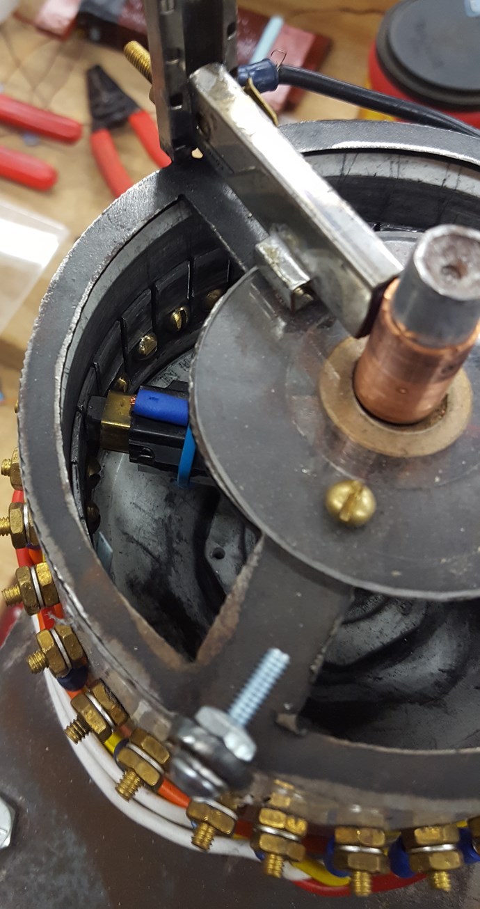
A different way to wind the coils and their arrangment.

The attached photo of the coil layout is powered from a 12 volt battery which powers a 750 watt inverter giving a 120 volt AC output. This powers a Hammond 1182 L 30 toroidal transformer with a center tap and (2) 30 volt AC outputs. These out puts are180 degrees inverted and are changed to DC voltage at about 12 volts and 4 amps using heavy duty diodes . Each of these powers the primary coils that are bifilar wound with 136 turns of 16 guage magnet wire. Over these primaries is wound the paired output coils that are wound with 900 turns of 22 guage magnet wire. These are wound in series in such a way that their outputs add to give 2 out puts of 200 volts that are 180 degrees inverted. I plan to add about 70 more turns to each secondary coil to give 220 volts to each leg.


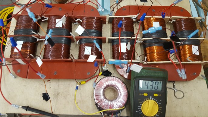
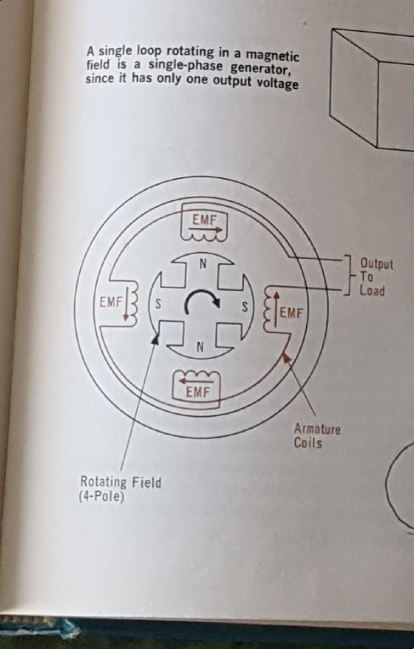
When the coils are powered up without a load the the readout of the inverter is zero. When a load of (2) 100 watt light bulbs is added to one of the output coil sets, the wattage on the inverter reads 174 watts. I am still getting additional test equipment to get an exact power reading of what happens with the light bulbs. The secondary paired output coils are wound in the fashion of Don L. Smith's device that is a high frequency device. I am planning to wind one set in the pattern of Chris's paired output coils to see if I can get better output with higher amperage.

Attached Files

Order By: Standard | Newest | Votes
Rakarskiy posted this 18 April 2022

Good patent, all knots are correct. In fact, followers of Clemente Figuera. Excitation of the primary transformer. Removal as a generator phase. In the figure in the patent, a slice of the plane, you need volume (3D) to read


https://rakatskiy.blogspot.com/2022/04/electric-solid-state-generator.html


Reading the definition:
"Electromagnetic induction is the phenomenon of the occurrence of an electric current, electric field or electric polarization when a magnetic field changes over time or when a material medium moves in a magnetic field."
For us, they mixed: electric current, electric field and polarization - for one reason, which is categorically not true.
On the section of the conductor, when using a magnetic field, a vortex electric field arises, which has an appropriate spin that determines (polarization) or the sign of the potentials at the ends of the conductor.
Current strength is a vortex magnetic field in a conductor. This vortex field appears only when the conductor, with a section of the vortex electric field, is closed into a closed circuit.
It is so obvious that following this paradigm, it is not particularly difficult to understand how the system - a solid-state electromagnetic generator - works. Skills are needed in the design of electromechanical and electric power transformer installations.

There is a war in my country, so I can’t write much, I hope I can finish what I started. All that I have worked out turned out to be the same as Clemente Figuera and this Canadian patent.


https://patentimages.storage.googleapis.com/f1/73/db/bddc31a19a8100/CA2357550A1.pdf

https://rakatskiy.blogspot.com/2022/02/the-war-in-ukraine-glory-to-ukraine.html

Chris posted this 15 February 2022

Hi Scalarpotential,

I am pleased to hear:

Chris, lol, it was just a lack of better words, lately mindfog gives me a hard time with words esp english...


I hope you can see my point of view and hope there are no hard feelings! I have seen so many trolls, and when I see some things, I get a little defensive, I am sorry for that! Its for All I do this, and for All I stand to expose what they have done!

Each Copper Atoms have 29 Electrons, and Electrons can be freed by Bucking Magnetic Fields, its Electromagnetic Pressure, that makes them move Up in Orbitals and then become Free, so Electric and Magnetic, being Electromagnetic together.

Many threads here, and many videos I have released explain this very simple, and well known phenomena:


What we do to the Electrons, at a specific time, in a specific State, deterimnes why the Electron moves, and the Electrons Energy State depends on its Orbital, excite the Electrons and they change State:


It is in the Vaelance Band, where Conduction occurs:


So this is where we need to move all the Electrons to! Then we can Accelerate them!, Thus a Current!

A good read of threads here, will give more detailed information.

However, it is just like we were told:

Ere many generations pass, our machinery will be driven by a power obtainable at any point of the universe. This idea is not novel. Men have been led to it long ago go by instinct or reason. It has been expressed in many ways, and in many places, in the history of old and new. We find it in the delightful myth of Antheus, who drives power from the earth; we find it among the subtle speculations of one of your splendid mathematicians, and in many hints and statements of thinkers of the present time. Throughout space there is energy. Is this energy static or kinetic? If static, our hopes are in vain; if kinetic - and this we know it is for certain - then it is a mere question of time when men will succeed in attaching their machinery to the very wheelwork of nature.

Nikola Tesla - Experiments With Alternate Currents Of High Potential And High Frequency (February 1892).


He was so far ahead, he could see!

Our job is to Free and Accelerate the Electrons we have in Copper Wire, or any other Conductive Wire!

Best Wishes,

   Chris

P.S: Another post Deleted by CD_Sharp, in reply to this post Here, Sadly! What an effort they went to in the End!

scalarpotential posted this 15 February 2022

Thanks Greywolf47, very clear explanation. The asymmetry must be the important part. I guess the setup is like this:  two electromagnets connected in series and driving a secondary coil between them.

Chris, lol, it was just a lack of better words, lately mindfog gives me a hard time with words esp english...

To be more specific, where does the analogy of "1+1+(-1)=1" appear in Firguera's transformer so au is allowed?  A dynamo in motion resists the prime mover when power is drawn, a secondary coil creates back mmf resisting the primary mmf when the induced current causes self-induction.

How is Voltage "Generated"? By mag induction, EMF is induced in each winding, the voltage at the terminals is the sum of the EMF in each winding.

How is a Current Pumped? Pushed by the electric field of the induced voltage. The same current also flows through the coil causing self-induction and back mmf.

How does Figuera negate or reverse the effect of back-mmf to the 2 primary coils? I'll think about it myself.

cheers

  • Liked by
  • Augenblick
  • Chris
Chris posted this 13 February 2022

My Friends,

This Question:

anyone who can explain in short how the Figuera generator works, what the technique is to achieve the claim?


All Members should have a very good base understanding on the answer to this question already!

This is a rather disappointing question to see and read on My Forum!

To Power a Load, one must have:

  • Voltage
  • Current


  1. How is Voltage "Generated"? We have already answered this Question!
  2. How is a Current Pumped? We have already answered this Question!
  3. Where does the Elementary Charge come from? We have already answered this Question!


So, Greywolf47 is correct and accurate in his answer and Clemente Figuera has already told us exactly the same thing:

PRINCIPLE OF THE INVENTION - Watching closely what happens in a Dynamo in motion...


The Electric Generator is an Incomplete Technology! For some 191 Years, Engineers have been too damn DUMB to work out Electromagnetic Induction as it is clearly seen to any Free Mind! Brain Washed Buffoon's desperately try to make a Field of Exploration, specifically the Completion of Electromagnetic Induction, VooDoo, Conspiracy Non-Sense because they are too damn Dumb to see past their Indoctrination, or Pay Check!

The use of the terms: "achieve the claim" is an embarrassment to Science! When Science is so far behind on a 191 Year old Technology! When people in their Back Yards are further ahead than the Scientific Community, and people speak like this, it is lack of Education and Free Will, or a Denial of The Wheel Work of Nature, either by Choice or by Ignorance, of Natures most simple things!

The very definition of Science:

The intellectual and practical activity encompassing the systematic study of the structure and behaviour of the physical and natural world through observation and experiment.


Shows how Incompetent majority of the Community is, and always has been! Words used by The Goon Squad from times past, on another Forum to dissuade Others from following Scientifically, the Exploration that lays ahead!

I am embarrassed to see this string of words on My Forum!

Best Wishes,

   Chris

Greywolf47 posted this 13 February 2022

Scalarpotential, I will try to make it short and simple. A normal generator creates an electrical current when a moving magnetic field (field coils) move past the stator coils which are stationary. This movement is accomplished by a prime mover( hydro, motor, or nuclear-powered steam turbine) to provide the force needed to turn the armature containing the field coils. Clemente Figuera sought to negate this prime mover by making ALL parts stationary and ONLY making a variable flux field in the primary windings ( field coils of the moving armature). The secondary windings see this variable flux the same as movement and therefore create a current just the same as a dynamo WITH movement. There are other dynamics involved in the asymmetric winding of the coils that allow for the greater output that the input needed to charge the primary coils. The is also the tank circuit effect with induction coils and capacitors that is also in play. I hope this brief description of the principle of the apparatus is helpful. Greywolf47

scalarpotential posted this 09 February 2022

Hi,

anyone who can explain in short how the Figuera generator works, what the technique is to achieve the claim? I can't find good and clear info on it.

Thanks & Take care

  • Liked by
  • Augenblick
  • Greywolf47
Chris posted this 08 January 2022

Hey Greywolf47,

I hope the move went as well as a move can go! Moving is often difficult.

Best Wishes,

   Chris 

  • Liked by
  • Augenblick
Greywolf47 posted this 07 January 2022

Just a quick update on my status as well as build status. I have recently moved from Tennessee to Kansas and have moved to a much smaller work space. I have gotten set up and am continuing on my Clemente Figuera replication. Thanks for your patience.

Chris posted this 21 December 2020

Hello Greywolf47,

If I may recommend, The Mr Preva Experiment is the best experiment on this forum to show Current Amplification, if you can properly understand this Experiment, then you can properly understand HOW Current is Amplified and Pumped. The Lorentz Force is responsible for Accelerating Charge.

There is a great deal to be learnt, in this very simple, cheap, Experiment! This will save you a massive amount of time!

What is the Source of the Electrons:


A single Electron, the Copper Atom having 29 Electrons, has a Charge ( e ) of: -1.602176634×10⁻¹⁹ C


A Voltage, of One Volt, which is also equal to One Coulomb, has: 6.24 x 10¹⁸ Electrons  

One Ampere, is this very same Coulomb, moving past Terminal T1 in one Second, the Flow Rate of this Coulomb.


This is why, we see, Ohms Law, show us: 1 Amp x 1 Volt = 1 Watt. The Watt has Time t associated with it directly, 1 Second. Often the term Watt second is used, but mostly just "Watt". 

Each Electron, by definition, comes from the Atom, outer Orbitals, where Electrons on inner Orbitals can be made to move up in orbitals by adding Pressure, adding Energy.

We have many very important pages on this forum, all containing important information like the above! It is worth studding this very important information to understand what your Goal is!

Best Wishes,

   Chris

Greywolf47 posted this 21 December 2020

My understanding, and this changes quite often, is that the two secondaries that are wound over the bifilar wound primary are wound with the primary CW and one of the secondaries being wound CW. The other of the paired output secondaries is wound CCW. As the primary current is reversed by current from the opposite end of the core, the collapsing field actually is in the same direction as the new current building until maximum current is reached. As I understand, voltage is created on the positive side of the sine wave and amps are generated on the negative part of the sine wave.

  • Liked by
  • Augenblick
Chris posted this 20 December 2020

Hello Greywolf47,

I think, from what I see, you're on the right track!

Where do the Amps: 6.24 x 10¹⁸ Electrons per second = One Ampere, come from? What's the Source and Catalyst for this Flow?

I don't think I need to ask about Voltage as we all know the difference is Charge Potential between Terminal T1 and T2, this part is simple and obvious.

I only ask, to help, so please don't take this the wrong way.

Best Wishes,

   Chris

  • Liked by
  • Greywolf47
  • Augenblick
Greywolf47 posted this 20 December 2020

The very simple diagram that I posted of a single phase generator clearly shows clockwise and counter clockwise windings in the stator coils with the CCW reversed in direction from the CW coils. This creates the asymmetry you speak of. What I am building is not a transformer, but a true generator that doesn't turn. The opposing bifilar wound primary coils overwound with opposing secondaries wound over them, gives the 1 minus 1 plus one giving voltage and amperage. In TESLA'S patent he shows three ways to do the coil winding. In figure 1 he show a center connection of a coil all wound in the same direction. In figure 2 he shows the bottom half after the ground in the reverse direction. As I understand, this is the way your paired output coils are wound. Then there is a figure 3 drawing where the M coil is full length in a CW direction and then back wound as bifilar wound halfway back with a center ground attached at the reversal. Don Smith said this type of winding gives greater amps.

  • Liked by
  • Augenblick
Chris posted this 20 December 2020

Hello Greywolf47,

Re your Theory of Operation, I was asking about ensuring Voltage and Current Flow on the Output, as I see nothing on Voltage and Current Flow on the output.

Of course anyone can wind a few coils!

I think ensuring one has a Magnified Output over and above the Input is of course the key and a very specific understanding is required to make this happen! Its not just a case of more turns!

Figuera said study the dynamo, and you are, this is good to see! There is a little more to it, however, a simple Transformer is not Above Unity, he left a very important part out!

Asymmetry of Magnetic Fields is the Key!

If you don't mind me saying, gaining this very important understanding before you spend more money on builds, can be very beneficial, save you a lot of time, money and heart ache!

Best Wishes,

   Chris


  • Liked by
  • cd_sharp
  • Augenblick
Greywolf47 posted this 20 December 2020

I have been studying some of Don Smith's videos and at the 2001 symposium he shows a detailed closeup of his high frequency coils that he states that he " took out 2 turns in the middle". That coil is definately a single coil, all turning in the SAME direction. In the center, the wire comes over the top and to the center tap. The other center tap wire goes in at the bottom of the coil to continue the second half of the coil.

Greywolf47 posted this 19 December 2020

Chris, about 4 days ago, you asked me about the theory of operation for my build out of Clemente Figuera's device. There will be laminated iron core primaries that are bifilar wound but the ends are not connected. Instead each wire is powered with a positive DC pulse at 60 Hz from one direction and pulsing at 60 Hz but phased 180 degrees inverted. The other wire in the coil is charged from the opposite end. This causes a rapid reversal in the magnetic flux and a reversal of polarity. The number of turns of these primaries and guage of wire is tentatively set at 136 turns bifilar wound (272) loops of 16 guage magnet wire. When I get all seven sets of 3 primaries wound, I may need to reduce the number of turns. The secondaries are paired and wound over the primaries with 980 turns of 22 guage magnet wire. Here again this may change to get the correct output voltage. The primaries are charged with 13 volts DC at 4 amps from the output of a Hammond 1182 L 30 toroidal transformer with a center tap. The 30 volts AC from the transformer is changed to DC by the use of a heavy duty diode on each output leg. The current of one output leg is fed into the series of primaries from one end and the other current is fed in from the opposite end of the primary set and 180 degrees inverted. The output from the first primary coil is fed into the adjacent coil in series from the opposite direction as the first coil. When all the primaries have been charged from this current, the inverted charge is entered into the primaries set from the opposite end and paired where the ground wire came out from the first current pulse. This current flow causes the secondaries to be charged in opposite directions so that the pattern of charge is N to S to N to S in one direction for 180 degrees of the sine wave and then all poles reverse when the current comes back in the opposite direction. This pattern should give the same output as a dynamo stator coils of a generator. This will be a single phase output. When this unit is perfected, I anticipate a 3 phase unit to follow.

  • Liked by
  • baerndorfer
  • Augenblick
Greywolf47 posted this 18 December 2020

Everything in a generator or dynamo stator happens in milliseconds and in sequence and order at the speed of light. When you go from single phase to three phase, it gets faster and more complicated. I have not yet come up with a way to replace the commutator for a 3 phase device because that commutator has 6 brushes (3 pairs) that are 120 degrees offset. This ultimately may have to be done digitally with 555 timers and solid state circuits. This is above my level of understanding at this time. Anyone on the forum with that expertise is welcome to comment. The single phase commutator with a single phase output CAN be replaced very effectively with a toroidal transformer with a center tap. The toroidal transformer I am using is a Hammond 1182 L30 with center tap. I use a heavy diode to convert the 30 volt output to DC at about 14 volts at 4 amps. The two outputs are 180 degrees inverted just like the commutator at about the voltage of a hot 12 volt battery.

Greywolf47 posted this 18 December 2020

The advantage of spending the time and resources to build the commutator and resistors is that it will give the ability to study the magnetic flux at a great deal LESS than light speed. Everything that happens to create what we seek has to be able to visualize what is otherwise invisible.

  • Liked by
  • Chris
  • Augenblick
Greywolf47 posted this 18 December 2020

I know that this gives me great advantage and I am most fortunate. I am also retired and can spend more time than most and to devote resources to finish the task. I am always open to critique and suggestions if anyone sees a better way forward.

  • Liked by
  • Vidura
  • Augenblick
Greywolf47 posted this 17 December 2020

A lot of the parts and pieces of this machine are available from most hardware stores. However, there are some specialty parts and pieces that I had to have my son make for me. He has a metal fabrication shop with a CNC plasma table that can design and cut any part I have need of to built my devices.

  • Liked by
  • Vidura
  • Augenblick
Greywolf47 posted this 17 December 2020

Rather than having a solid top on the commutator, I have elected to have a metal plate that is slotted with cutouts. This makes it self cooling as well as allowing me to see what is going on with the contacts and how much sparking is going on. Sparking is bad and indicates that something is probably not wired correctly.

  • Liked by
  • Vidura
  • Augenblick
Greywolf47 posted this 17 December 2020

Just below the speed control is a white on/off switch that turns the motor on and off. The cream colored switch controls the current from the battery to the commutator. It is VERY IMPORTANT that the motor is turned on before the current to the commutator so as to not damage the carbon brushes and contacts. The damage will be arcing, and depending on the position of the carbon brushes, may even melt the aluminium contact such that it would be necessary to replace them due to damage.

  • Liked by
  • Augenblick
Greywolf47 posted this 17 December 2020

Behind the cream colored on/off switch is the fan housing of a cooling fan connected to the DC motor mounted beneath that turns the fan and commutator. In the foreground is a variable speed controller so I can slow down the cycles per second so that I can study what is happening with the magnetic flux.

  • Liked by
  • Vidura
  • Augenblick
Greywolf47 posted this 17 December 2020

I put the old heater coil in the picture as reference so you can see how it was built but I no longer use it. The induction coil setup is much better.

  • Liked by
  • Vidura
  • Augenblick
Greywolf47 posted this 17 December 2020

In the photo above you can see the different colors of paired wires that go from the outside circumferance of the pipe collar housing of the commutator down to the resistor coil set. Red wires carry full current, orange wires carry 80% current, yellow wires carry 60%, and white 40%. The current to the opposite pole of the primary coil is increasing so that the second white is carrying 40%, as the other decreases to 20%, etc. I started by using the heater coil out of a home furnace but found that it caused too much energy loss as heat that was not recoverable. I built a 7 coil inductor setup that would change the energy flow like the heater coil, but without the heat loss because as the coils are de energized, their energy is not lost.

  • Liked by
  • Augenblick
  • Vidura
Greywolf47 posted this 17 December 2020

here is an overview of the complete commutatorcommutator

Greywolf47 posted this 17 December 2020

The brushes I am using are made for use in a vaccuum cleaner motor and have a plastic housing with a brass sleeve that holds the carbon brush. It is very important that the aluminium contact plates be spaced without touching and so that their edges are even so the carbon brushes move smoothly from plate to plate without resistance or bouncing.

  • Liked by
  • Vidura
  • Augenblick
Greywolf47 posted this 17 December 2020

The ring of brass screws and nuts hold the aluminium contact plates in place as well as connecting the wiring that connects to the resister bank to vary the current to the coils.

  • Liked by
  • Vidura
  • Augenblick
Greywolf47 posted this 17 December 2020

The current from a 12 volt battery comes in at the carbon brush in contact with the copper sleeve. This takes the current down to the brush holder. There are two carbon brushes running 180 degrees opposed. Where the small blue connecter is in the photo you can see the brass holder and the black carbon brush in contact with the aluminium contact plates on the inside circumference of the 4 inch plastic pipe collar that is the body of the commutator.

  • Liked by
  • Vidura
  • Augenblick
Greywolf47 posted this 17 December 2020

Here is a photo of my commutator.

Greywolf47 posted this 17 December 2020

I began with other devices that were energy generating devices, several of them by Don Smith but I found them, at the time, to be too technical for my understanding at that time. When I came upon Clemente Figuera's infinite energy machine, it appeared to be a much more mechanical device with more of the requirements of my skill sets. I began by building the commutator because without being able to vary the current to the coils, it is impossible to build a static device. The first commutator I built had the 16 contacts inside just as Figuera had in his patent. The problem that came with that is that to get 60 Hz or 60 cycles per second, the brush had only one contact and had to turn 3600 rpm. This caused a great deal of vibration and noise and was very difficult to keep at a steady rpm. I built a second commutator with 32 internal contacts so that I could use 2 carbon brush contacts 180 degrees opposite. This balanced the rotor and stopped about 98 % of the vibration. It also allowed the rpm to be dropped to 1800 rpm and still get 60 cycles per second.

Attached Files

Greywolf47 posted this 17 December 2020

I have realised that when I started posting on this thread, I began posting where I am in my research and not how I got here. Anyone wanting to reproduce my reproduction will need to have the background to understand WHY it is necessary to do certain things to be able to build a successful device.

Greywolf47 posted this 16 December 2020

This is a page from the book I mentioned earlier that shows the direction of winding on 
N and S  coils and how they are arranged in series to get maximum output.

Greywolf47 posted this 16 December 2020

Greywolf47 posted this 16 December 2020

Thanks to all for the help . I'm getting a cable to down load my photos to my desktop computer and post from there.

  • Liked by
  • Chris
  • Augenblick
cheors posted this 16 December 2020

https://www.irfanview.com/

cheors posted this 16 December 2020

I use Irfanview. With a batch conversion capability and a lot of smart functions

Greywolf47 posted this 16 December 2020

Thanks for the help. I've got to get a cable with USB terminal that will connect to my iphone to get my photos over to PAINT. I'll get there yet and promise some good stuff when I figure this out. Here I am working on world changing technology and can't figure out the tech to post it. LOL😆

Chris posted this 16 December 2020

GW,

Hope this helps:


Best Wishes,

   Chris

  • Liked by
  • Greywolf47
  • Augenblick
Greywolf47 posted this 15 December 2020

Thanks, Viura, I will try that. It is very frustrating to have information to share and knowledge to give but not be tech savy enough to get it done. LOL

Vidura posted this 15 December 2020

Hey Greywolf, I recommend to use an app for resize the images, I use litfoto in my phone, works perfect and without a lot of advertising. So you can reduce the size of you images from various Mb to a few hundred kb . For videos similarly are applications capable of resizing for download. Vidura

  • Liked by
  • Chris
  • Augenblick
Greywolf47 posted this 15 December 2020

Still can't get it to load a picture of 1.6 mb. Sorry I'll keep trying.

Attached Files

  • Liked by
  • Chris
  • Augenblick
Greywolf47 posted this 15 December 2020

Still can't get it to post. Will keep trying.

Attached Files

  • Liked by
  • Chris
  • Augenblick
Greywolf47 posted this 15 December 2020

I promised a video of the changing magntic flux with the commutator slowed down to about 3 cycles per second.

  • Liked by
  • Chris
  • Augenblick
Greywolf47 posted this 15 December 2020

I am back to bench testing different coil primaries and secondaries using the commutator and resistor set up to try and get photos I can post to show the magnetic flux moving from N pole toward S pole and then back again like a seesaw. Should be able to post that soon.

Chris posted this 14 December 2020

Hey GW,

Yes, its a little more difficult on ones phone. I recommend use the File Manager for all, Videos, Images and documents. This will be much easier.

Best Wishes,

   Chris

  • Liked by
  • Jagau
  • Augenblick
Greywolf47 posted this 14 December 2020

If I understand correctly ( and I'm NEVER certain of that), each line of flux carries the SAME number of electrons reguardless of how far from the core they are located. The length of the flux lines get longer as you move away from the core and the spacing between the electrons gets greater, but the TOTAL number of electrons in each flux line is the same. The further the flux line is away from the core, the weaker it gets, but the number of electrons in that flux line is the same as the ones closer into the core.

  • Liked by
  • Augenblick
  • Chris
Greywolf47 posted this 14 December 2020

A question that needs to be answered: When the magetic flux is flowing INSIDE the iron core, it is very concentrated, but when it flows out of the N pole of the electro magnet it is dispersed into lines of flux that flow from N poles and enter back into S pole. While it is passing through the aether that is filled with electrons flowing in RANDOM directions, how much of these random free electrons can be captured by the flux lines and ADDED to the total electron flow? IS THIS the free energy we are seeking?

Greywolf47 posted this 14 December 2020

When the wave goes below the zero point, the flow reverses and the process reverses, so that N poles become S poles and the electron flow is in the opposite direction. The SAME electrons that just went one way are now flowing back in the opposite direction! And this happens 60 times per second. So if you are flowing 10 ampheres of current, there is 6.24 times 10 to the 18th power times 10(amps) divided by 120 ( 1/2 cycles) gives the number of free electrons being pumped in each direction of the AC current.

Greywolf47 posted this 14 December 2020

Some background information for those studying energy devices. When looking at waves on an oscilloscope, you see 60Hz as 4 to 5 waves on the screen. In real time, each of those waves from peak to peak is a little over 3100 miles! When you think that electricical current induction in a coil actually resists the change, the flow of current is slowed down by resistance so that the second coil in a series of coils does not begin to charge up until the current in the first coil has reached it's maximum. This may only take milliseconds, but it is miles down the 3100 mile wave. If you have 21 primary coils all charging in series as in my device and the 42 secondaries are being induced at the same time each one is miles apart on the wave. This creates an electron pump that is pumping that 6.24 x 10 18th electrons per amp down the wire. It happens in miliseconds, but it all is in order.

Greywolf47 posted this 14 December 2020

Chris, I have been only using my cell phone to read and write messages but I think to load videos and photos I will have to use my computer. Any suggestions on how to convert photos and videos from phone to computer?

  • Liked by
  • Vidura
  • Augenblick
We're Light Years Ahead!
Members Online:

No one online at the moment


What is a Scalar:

In physics, scalars are physical quantities that are unaffected by changes to a vector space basis. Scalars are often accompanied by units of measurement, as in "10 cm". Examples of scalar quantities are mass, distance, charge, volume, time, speed, and the magnitude of physical vectors in general.

You need to forget the Non-Sense that some spout with out knowing the actual Definition of the word Scalar! Some people talk absolute Bull Sh*t!

The pressure P in the formula P = pgh, pgh is a scalar that tells you the amount of this squashing force per unit area in a fluid.

A Scalar, having both direction and magnitude, can be anything! The Magnetic Field, a Charge moving, yet some Numb Nuts think it means Magic Science!

Message from God:

Hello my children. This is Yahweh, the one true Lord. You have found creation's secret. Now share it peacefully with the world.

Ref: Message from God written inside the Human Genome

God be in my head, and in my thinking.

God be in my eyes, and in my looking.

God be in my mouth, and in my speaking.

Oh, God be in my heart, and in my understanding.

Your Support:

More than anything else, your contributions to this forum are most important! We are trying to actively get all visitors involved, but we do only have a few main contributors, which are very much appreciated! If you would like to see more pages with more detailed experiments and answers, perhaps a contribution of another type maybe possible:

PayPal De-Platformed me!

They REFUSE to tell me why!

We now use Wise!

Donate
Use E-Mail: Chris at aboveunity.com

The content I am sharing is not only unique, but is changing the world as we know it! Please Support Us!

Thank You So Much!

Weeks High Earners:
The great Nikola Tesla:

Ere many generations pass, our machinery will be driven by a power obtainable at any point of the universe. This idea is not novel. Men have been led to it long ago by instinct or reason. It has been expressed in many ways, and in many places, in the history of old and new. We find it in the delightful myth of Antheus, who drives power from the earth; we find it among the subtle speculations of one of your splendid mathematicians, and in many hints and statements of thinkers of the present time. Throughout space there is energy. Is this energy static or kinetic? If static, our hopes are in vain; if kinetic - and this we know it is for certain - then it is a mere question of time when men will succeed in attaching their machinery to the very wheelwork of nature.

Experiments With Alternate Currents Of High Potential And High Frequency (February 1892).

Close