ISLab's Replication of Basic POC Effect

  • 3.2K Views
  • Last Post 04 November 2022
ISLab posted this 10 January 2022

This is my first attempt to replicate the basic POC OU effect.

First I want to thank Chris for this extraordinary site and its amazing content! I only came across it recently and wish I had known of it for the last few years that I have been experimenting. But it is never too late, so I want to start from scratch with POC effect.

Since this is my first post and the interface is very new, please forgive any errors. I will learn and correct as I go along.

My goal is to document in a way that others can also replicate by following my mistakes and successes.

I wound three coils on a 8cm ferrite rod thus:

L2 99 turns CW followed by L3 99 turns CCW

Then L1 on top of L2 with 98 turns CW.

All coils made with 26 SWG.

I tried to pulse L1 with 3.6 volts from standard PSU using IC555 circuit. This did not give any effect as the frequency was too low and I had no idea of what would be the resonant frequency.

The solution was to use Jagau's SRO circuit which automatically oscillates at resonant frequency, which I found to be about 12KHz in this case.

Below are photos and oscilloscope captures.

Coil and SRO circuit by Jagau

In order to get any useful signal on L3, I had to add a resistor and diode in both L2 and L3.

With resistor value of 33 Ohms and diode in opposing directions, I got the following in L3:

Red is pulse going into L1

Yellow is floating signal in L3, without connecting ground which seems to kill the signal.

Zooming in on this:

Slight adjustments on R1 give the following two variations to the pulse:

All the above readings are taken in the junction of the resistor and diode. The following is taken at the junction between L3 and diode:

I'm thrilled to get the ringing waveform but am not sure if I see the OU effect clearly lasting beyond the end of the L1 pulse.

Hence I request your guidance on how to further optimise the effect.

Thank you for your help and guidance!

Order By: Standard | Newest | Votes
ISLab posted this 25 January 2022

Update on POC effect

I just build the Swagatam TL494 based pulsing circuit recommended by Jagau here: https://aboveunity.com/thread/brian-s-eternal-flashlight-replication/?order=all#comment-3dffdba8-949a-4fcf-a24e-ae2600df671c which is published here: https://www.homemade-circuits.com/simplest-pwm-modified-sine-wave/

and tested it on the existing used coils last used in the experiments above.

Immediately the coils started "singing" loudly low frequencies below 1KHz, and at a certain duty cycle above 10% the Ecores snapped together tightly and began to vibrate on the table. The PSU started cutting off due to current overdraw. I increased the current limit and the MOSFET grew so hot there was smell of burning. So I reduced the duty cycle and played on the edge, then took photos of the scope before and after the sudden increase.

This is before: (Yellow is L1 input voltage, and Red is L2 current)

PSU showed voltage as 7.2v and current as 0.26A.

Keeping frequency the same but raising duty cycle entered the loud vibrating zone. Scope waveform began to fluctuate with pulses seeming expanded and compressed alternatively, as if frequency modulated, as here:

and here:

Note that the current in L2 has shot up from 0.8mA to 1.4mA. Frequency and duty cycle readings are unreliable due to fluctuations. But F settings was the same, and duty cycle was above 10% and approaching but less than 20%.

PSU current indicator was wildly fluctuating 0.05A to 1.6A. Nothing was stable. And the E-cores and coils were loudly vibrating and singing.

This is definitely something important. It looks life a strong magnetic interaction between L2 and L3. But instead of input current dropping, I get input current shooting up.

This is unknow territory. Request you to please advise how to proceed.

I also need advice on how to protect the MOSFETs from getting so hot. If the effect requires this level of currents as an intermediate stage, I do need heatsinks or some other protection, but don't know best practices.

Postscript

I tried the same coils with my previous pulsing circuit at same frequency, duty cycle and voltage, but got only the sawtooth wave without any of the singing and vibrating of the coils. Even the magnetic attraction between Ecores is missing. The only difference is that the new circuit uses MOSFETS at the output stage, and the old circuit had transistors. Most likely this just give far sharper rise and fall times.

ISLab posted this 05 February 2022

Dear Chris,

Thank you for pointing out my deviation from the Sawtooth waveform. I got distracted with circuit improvement along the way and failed to notice this. This won't happen again!

Yes, I take all your posts as constructive criticism, as I have seen your posts helping and guiding so many people on so many threads over so many years. Your guidance is invaluable, and I know it comes from genuine and compassionate commitment to help everyone and to disseminate this knowledge and Technology as widely as possible -- a goal that I too am fully committed to.

I can also understand your frustration in trying to help others for so many years, sometimes succeeding and often failing, all while fighting trolls and running your own server. This is like running three full-time jobs at the same time!

I hope you too can recognise that I'm here with a very different level of commitment to this work, and I hope that I have not only drawn full benefit of your guidance, but also by documenting in detail, made it easier for other newbies to implement with the necessary details that they may need to succeed while avoiding my mistakes.

Since discovering your website, my biggest difficulty has been insufficient details on implementation while being overloaded with so many rich and valuable threads of the theory and seeing others' final screenshots of results but without details of practical steps in between. Things which are obvious to you (from so many years of work, knowledge and expertise) are not so obvious to someone new to POC Tech. Although I come from a reasonably deep OU literature study and some active background of experimentation with OU, I still had to gather fragments from various threads and put them together with some guesswork until I got results. And most likely I would not have succeeded without your active guidance.

In part, this is the reason why I have been carefully documenting each step in as much detail as possible, so that others who come to this site with even less knowledge and skill than I have -- but with just as much commitment -- may find my documentation inspiring and helpful to successfully implement.

The other reason for documenting is because that is how I like to work in this kind of research so that one can always go back to an earlier stage of experiment without problem. Looking at my internal documentation (where I take images of each layout of circuit, probes and coils before taking each screenshot), I can now go back to exactly the point where I lost the linearity of Sawtooth, find the cause and make suitable corrections. I will do this and revert with a post soon, so that others can avoid making the same mistakes.

I got lost with circuit improvement because my first breakthrough came with using MOSFETS instead of transistors. And reading from your Timing and Nano Second Pulses threads gave the impression that circuit timing was critical. From my experimentation, I now realise that the basic POC effect may not need all that. But there was no context anywhere to gain this clarity except by experimenting and making mistakes.

Focus Specifically on Coil Interactions, Specifically the "Important" areas, then you will see more progress!

Yes, I shall. And with gratitude for your guidance and course-correction.

I will still have to rely on some guesswork as to what I need to do to improve coil interactions. But with feedback and guidance from you and others, I'm sure to succeed.

Dear Melendor,

Yes, I will close this thread soon, once I have fully "understood" the basic POC effect. I'm not satisfied with just an exact replication of Chris' construction because that is not enough to gain full understanding that will allow for developing the POC Tech. For this, I need to play with variations of all parameters, improve and optimise as far as possible. In the process and I will make mistakes and occasionally lose my way. But this is a small price to pay for steps towards mastery of any technology.

Once I take this to the level of satisfaction, I will close the thread with a summary and guidelines for those who want to replicate. The next thread will then be "efforts to amplify POC effect". And hopefully the third thread will be "efforts to close the loop".

ISLab posted this 24 January 2022

Thank you Chris! This gives me the hint to proceed.

By what percent does L3 improve performance? Disconnect and measure, Connect and Measure, you should see a drop on Input, when L3 is Connected, do you see this?

The PSU to pulsing circuit has too much noise for use with scope, so I put a mechanical milli-Ammeter on the 4.8v input.

Removing the diode makes the slightest ever drop on the needle which I visually estimate to be about 0.1mA. On the sawtooth waveform it makes a very slight dip in the angle of the descending slope -- easy to miss if you are not looking for it.

But when I reverse the diode on L3, there is a further drop on the meter (estimate to be about 0.2mA), and a more visible change in the waveform to this:

The difference between the clean sawtooth waveform and this reduced and curved waveform is the contribution of L3.

This is also the waveform when L3 is entirely removed from the Ecore! So diode reversal is equivalent to removal of L3.

What I don't understand is why and how L3 still makes a significant contribution to the POC effect even when it is left open (diode removed). Just its physical presence without connection significantly contributes to the POC effect. Can you please explain?


In your own words, what is occuring here, whats the fundamental Process?

A short pulse of current on L1 is provoking reaction in L2 by generating voltage and consequently some current in L2 circuit, which magnetically opposes L1 for the short duration of the pulse. Change in L2 current (+effect of L1 pulse) is then provoking counter-reaction in L3 which generates voltage (and some current) opposing magnetically against L2. The opposition of L3 magnetism on L2 magnetism forces more current flow in L2 (and I would assume in L3 also, but could not detect much) hence generating or amplifying power in L2. This magnetic opposition is the effect that now needs to be further optimised and amplified.

Please feel free to correct and clarify my understanding.

Summary and checklist

My purpose in this thread is to be able to document each step (including mistakes) to help and encourage others to replicate by showing how easy it is and including every possible detail. [Feel free to ask if I have missed anything.]

I started with a two-step goal: 1) replicate the basic POC effect, 2) amplify the effect until it can reach visible or measurable OU.

Checklist for step 1:

a) Get the sawtooth waveform of current flow in L2 -- CHECK

b) validate effect by removing diode in L3 -- CHECK (but weak)

c) verify that reversing diode in L3 cancels the effect -- CHECK

d) verify current drop in power input when L3 is active -- CHECK

At this point can I conclude that Step 1 is complete?

Directions of experimentation for Step 2:

Some thoughts here. Please advise on best way forward.

+ play with higher/lower Frequency and Duty-cycle to find points of magnetic resonance?

+ change turns in L2/L3 to match impedance more accurately?

+ play with L1/L2 turns ratio and wire-length ratio?

+ play with placement of L1 relative to L2/L3 for optimum effect?

+ any other suggestions or guidance?

Thank you all for continuing help and guidance!

Little Steps for Little Feet

with some hand-holding too!

ISLab posted this 25 January 2022

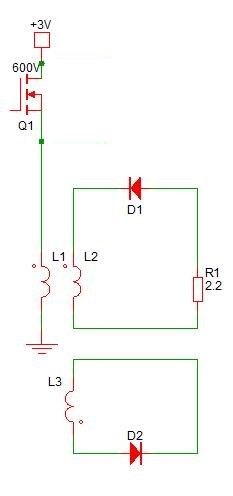
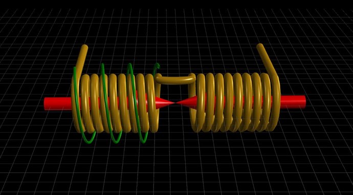
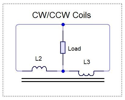
L3 Opposes L2 and L2 Opposes L1 thus L3 Assists L1, lowering the Input Current Required, focus on this and Understand this simplicity, then look towards Scale.

Thank you Chris for keeping the focus clear.

I would like to make a summary and survey of all the parameters and factors involved in optimisation (so far as I have understood) so that a suitable strategy can emerge for the steps ahead. Key point are followed by my thoughts and comments.

Objectives

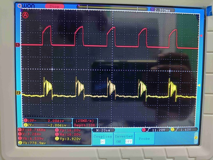
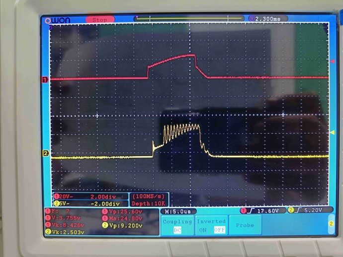
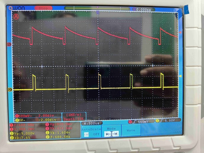
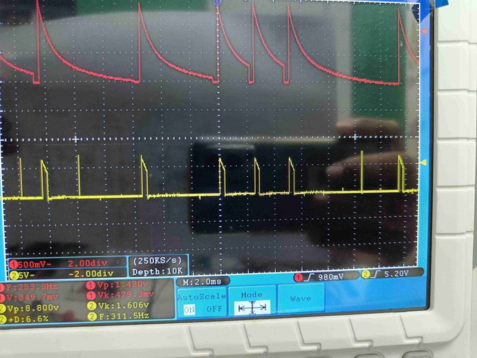
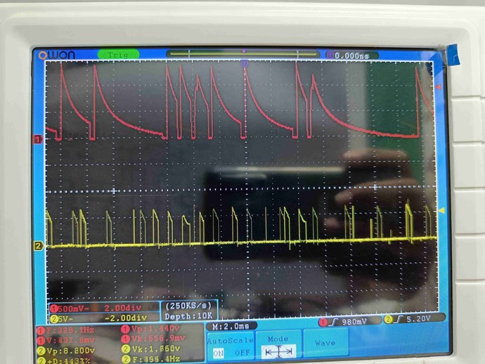
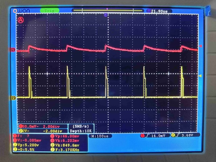
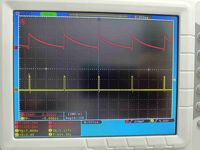
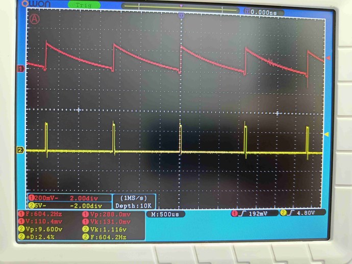
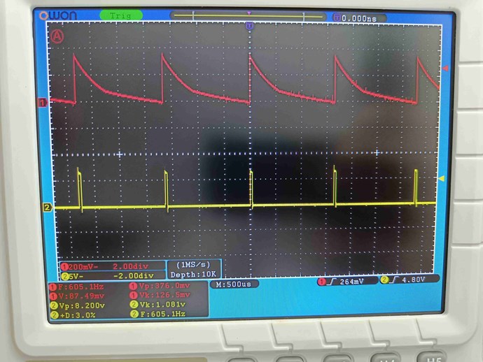
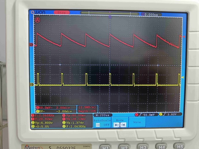
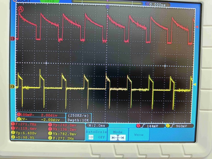
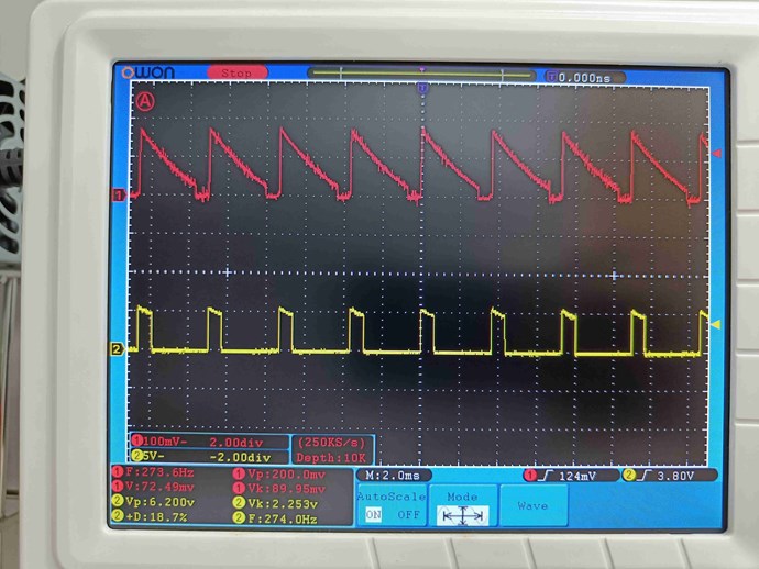
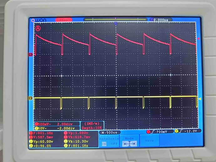
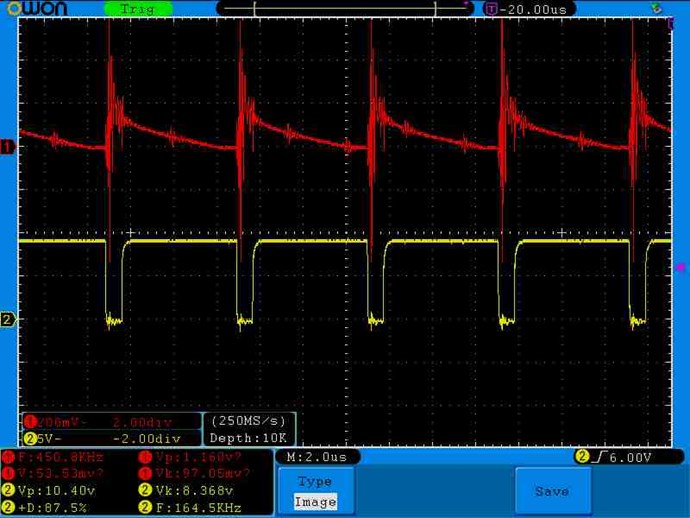
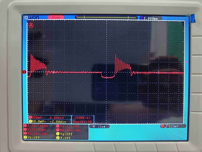
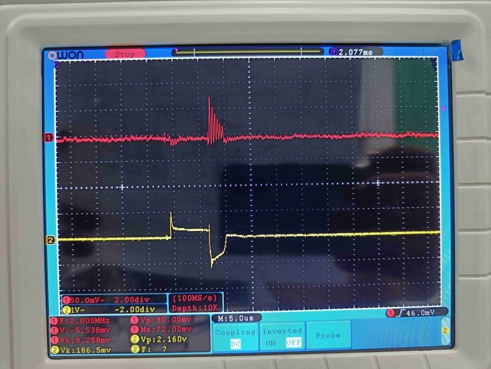
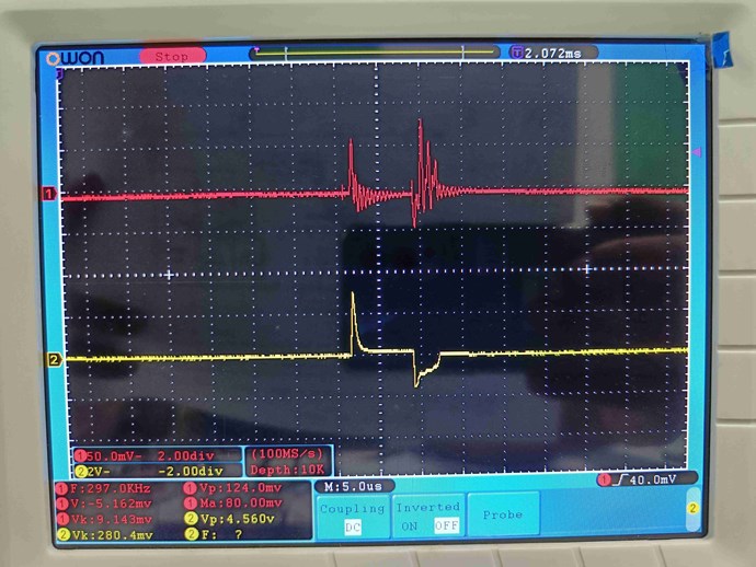
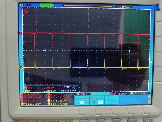
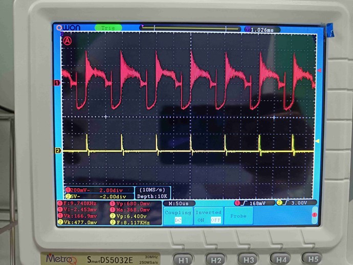
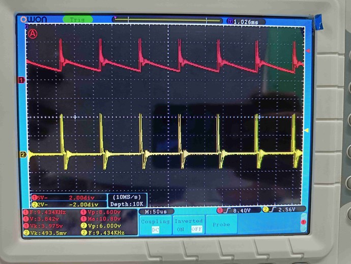
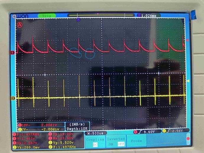
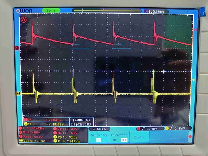
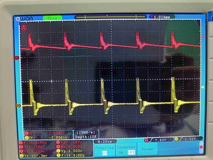
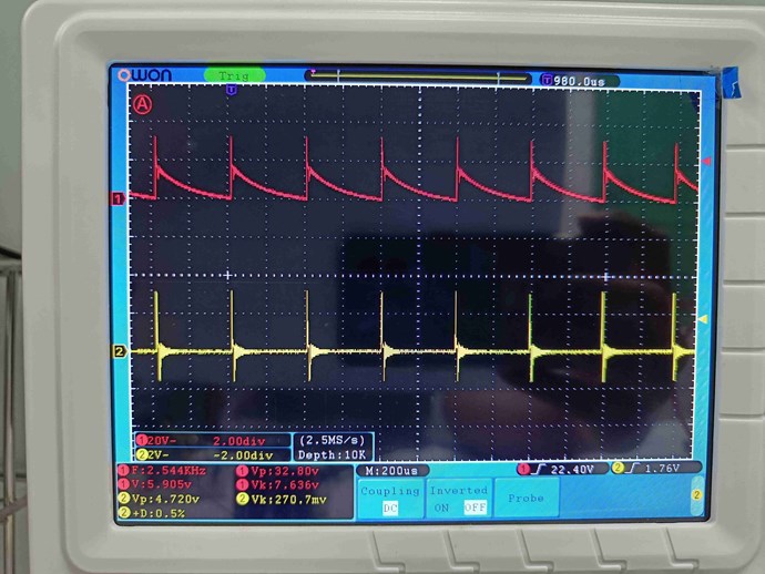
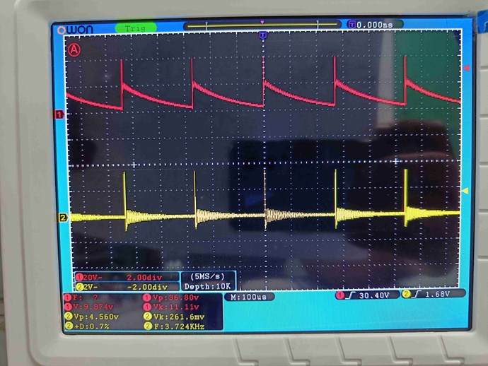
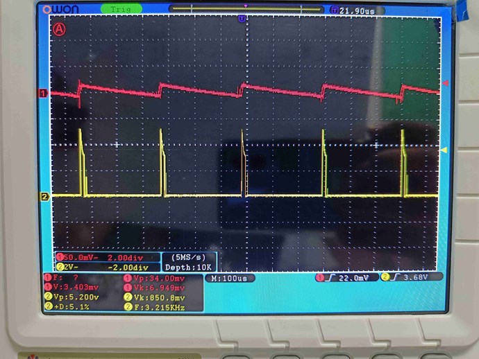
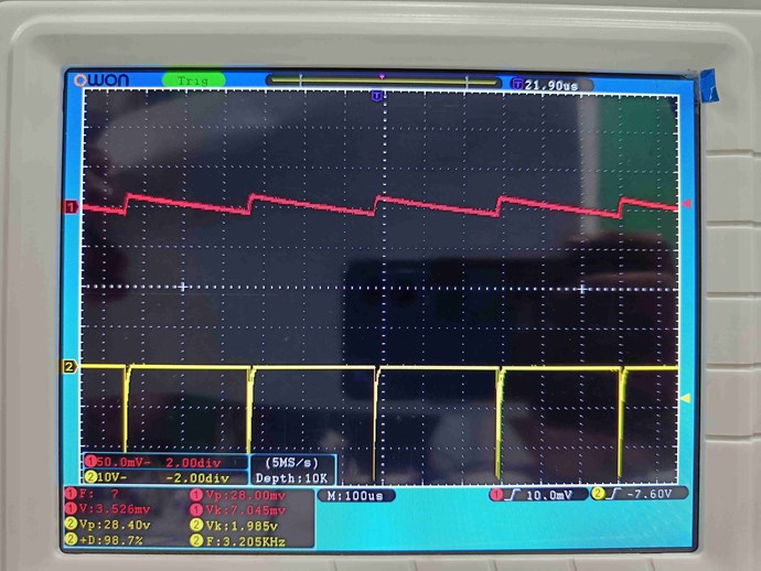
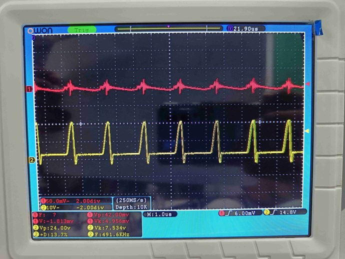
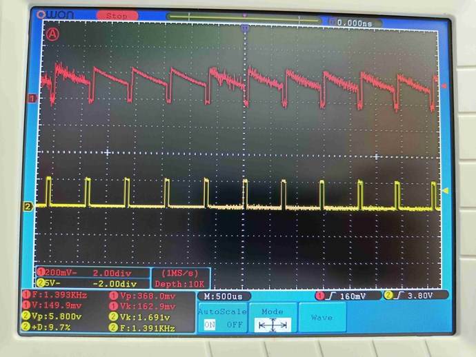
Two aspects to our focus: A) Get the magnetic fields to slap together with increasing intensity and precision of timing, B) watch for the lowering of input current as reference for improvement of A, and relative increase of sawtooth wave duration in proportion to duration of input pulse.

Parameters to optimise

Increasing of magnetic strength and correct timing requires the following placed as numbered points.
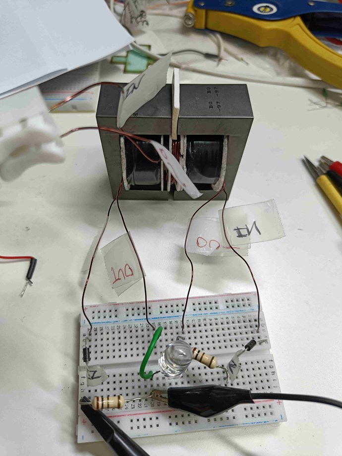
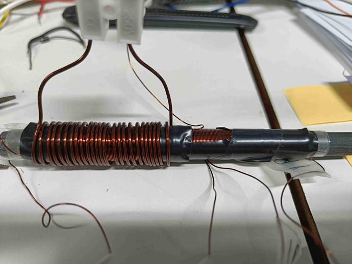
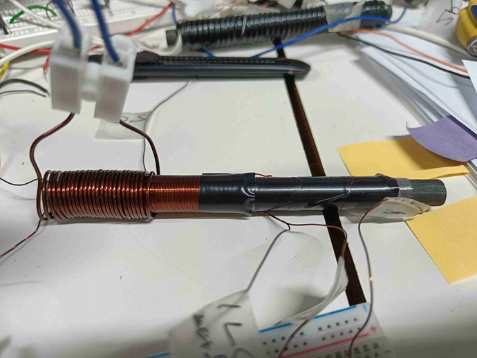
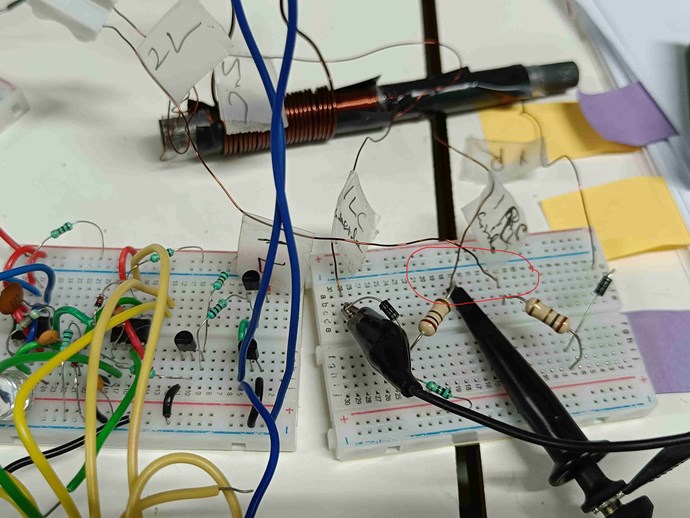
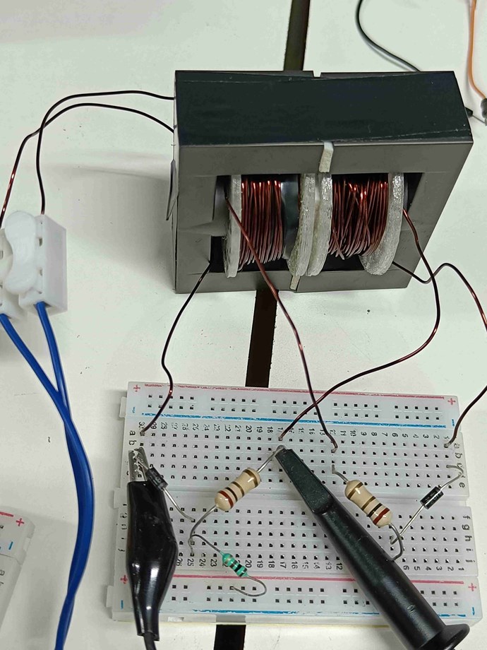
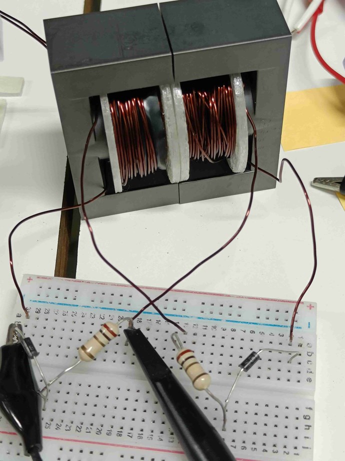
Coil geometry

1. increasing number of turns. This may require reducing wire diameter, but not so much as to limit current.

2. reducing length of coil (more turns per length). At the limit this means length of a single wire diameter with all turns one over the others, i.e. a pancake coil. But this will increase average radius too far from the core and so reduce field strength. A good compromise might be to make length equal or slightly more than the average distance of the layers from core.

3. increase cross sectional area (CSA) of magnetic flux and hence the inductor core. This makes the inductor core expensive and also increases wire length and hence resistance. Generally speaking with larger cores, the wire diameter also needs to get larger, keeping overall number of turns nearly same as for a smaller core, but yielding higher overall gains in current and power. Or wire length can be proportionally reduced with increased CSA to get the same field strength as a small core.

4. reduce core gap. Core gap is needed to boost fields strength, but reduced gap makes fields stronger.

The best practices recommended by Chris in coil geometry is:

The ideal, but not always practical rule should be, minimal Turns N of Maximum Wire Gauge AWG on the shortest possible Spool Length, giving a Short Coil Length l.

So a Large Cross Sectional Area CSA with a Short Coil Length l, and Large Wire Gauge AWG, will give best results for the Output!

Pulse generation

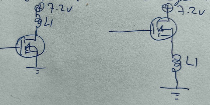
5. increase voltage of input pulse. This can increase field by square of voltage, so dangerous to go too high. But too low a value may not get enough field strength to produce useful effect (using up current to just magnetise the core and leaving nothing to induce in L2/L3), or may make the pulse edges not sharp enough as the driving circuit also needs minimum current for best edges. For now, will limit experiments to between 6v to 12v. Larger cores will need higher current to build the magnetic field before beginning to influence L2/L3.

6. increase the rate of increase of input pulse both in rise and fall. This requires good pulse circuits, use of MOSFETs, reduced resistance and reactance in input coil. So thicker and shorter input coil wire is better. Also, the closer L1 is wound to L2 the better in transfer of pulse without distortion.

7. faster circuit components. Use MOSFETs and diodes rated for high frequency, even on L2/L3 side of circuit which need to respond as fast as L1.

Timing / Magnetic resonance

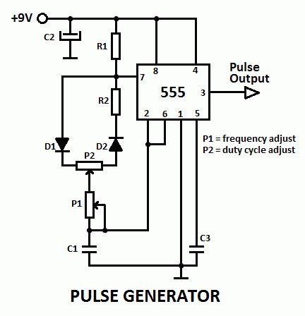
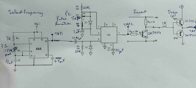
8. precise frequency of input pulse. The pulsing circuit needs to have precise and stable control of input frequency (F). One large variable resistor to sweep through a range, and another smaller one in series to fine-tune.

9. precise pulse-width or duty-cycle of input pulse. Although this can be seen as precise control of duty cycle (D), in actual fact I think it is the pulse width (W) which is more important (as discussed below). A circuit that offer separate control of F and D will be inconvenient as each change in F would require re-tuning D to keep pulse width the same. I believe the best kind of pulsing circuit will be one that offers separate controls for F and W, so that after fixing optimum pulse-width W one can freely adjust frequency F separately. See discussion below.

10. non-linear inductance, coil shorting, etc. These are advanced optimisations using MOSFETS inside L3 circuit, and other methods to get much higher results, which I list here for sake of completeness. But premature for my present stage of experimentation. Chris has several threads referring to these techniques.

Some thoughts on timing

My thinking on this is as below. Please treat this as logical but speculative until experiments confirm. I would request those who have already succeeded to advise or correct as they see fit.

Assuming no diodes, and L1, L2, L3 on a common core in this sequence, the rising pulse on L1 induces opposing voltage in L2 but also in L3 but with delay as it is farther. The increasing field in L2 generates opposing voltage in L1 and L3 at the same time, and the increasing field in L3 generates opposing voltage in L2 and with a delay in L1. While there is asymmetry, it is largely dependent on distance between coils and strength/weakness of influences.

Similarly the falling L1 pulse also induces the opposing voltage in L2 and L3, which then influence each other and L1 with delay between L3 and L1. These would be opposite of what the rising pulse induces.

Inserting the diodes changes this and forces a strong asymmetry. All inductions in L2 and L3 only create current when in alignment to the diodes. Within L2, only the inductions of one direction build, and within L3 only inductions in the other direction build (assuming correct diode directions). The overall result is that L3 assists L1 and lowers input current requirement, leading to the full POC effect. [I want to acknowledge with due credit a private PM from user Raivope in which he originally highlighted this role of the diodes.]

Since the rising and falling edges produce opposite currents in L2 and L3, in practice one edge induces L2 and the other edge induces L3. This can easily be validated if you have a difference in sharpness of rising and falling edges. You will then get better results with both diodes in one direction than both flipped in the other.

Assuming the rising edge induces in L3 and the falling edge induces in L2, the delay between the two should be a factor in attaining magnetic resonance and power generation. If our load is on L2, then L3 rising before L2 or falling after L2 will reduce overall power in L2 by opposing it. Ideally L3 should rise with L2 (or just after) and fall with L2 (or just before). If L3 is farther from L1, then the time taken for L1 pulse to reach L3 is longer thus allowing L2 more time to be induced by the falling edge, thus reducing the time lag between L2 and L3 inductions and giving better sync in POC effect. The opposite would happen if L2 was induced on the rising edge and L3 on falling edge -- the gap between the two magnetic fields buildup would grow much more. Ideally therefore both diodes should be aligned so that L3 triggers on rising edge and L2 on falling edge.

Here the importance of the pulse width becomes obvious as it should ideally be exactly the time taken for the magnetic pulse to travel the distance from L2 to L3 giving perfect timing for both magnetic waves to be induced together and to collide in sync. A slight separation between L2 and L3 also aids this timing (suggested by Chris). A slight difference in turns between L2 and L3 (also suggested by Chris) helps to ensure L3 falls before L2. [Chris's suggestions are here: https://aboveunity.com/thread/how-to-build-your-own-above-unity-machine/. I must clarify that the logical speculations here are mine and need not represent Chris' views. I only refer to his suggestions (which were posted in that thread without explanation) as the logic presented here justifies and explains the value of his suggestions.]

In case of other geometries of coil placement on different legs of E-cores or different locations on C-cores, the above logic and line of thinking will apply, although conclusions for timing optimisation may differ slightly. I believe this line of thinking can greatly improve overall design of coil layouts and of timing strategies. Perhaps this is already known to the advanced users here. But since I did not find this anywhere so far (and I've not yet read everything!) I offer this as hopefully useful for all.

Hence my thinking that control of pulse width is more critical than control of duty cycle.

That's all for now.

Please feel free to correct or add to anything above. My hope is that we can compile a comprehensive list of parametres relevant to optimisation.

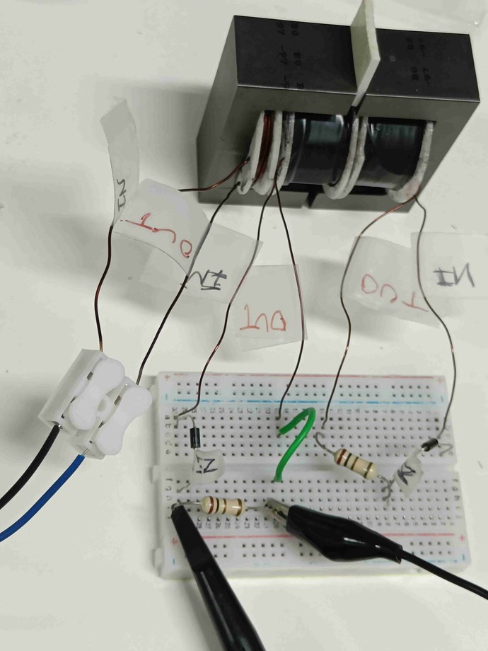
Here ends the speculation and theory. I will hereafter focus on results and continue to share experimental results as I go along.

This has been long post. Hopefully it will help to trigger discussion and lead to better optimisation.

raivope posted this 25 January 2022

Hi,

I it depends how to define a word "assists".

Ok, lets bring some life to this thread.

I have tested also different circuit variations and have concluded that the POC circuit is actually the following that produces the triangle wave.

Assumptions:
1. circuit:

2. L1 is wrapped over L2 (has a load), L3 is further away and has no load.

Circuit interpretation:

L1 is pulsed ON: L3 creates opposing current thru diode. L2 does nothing, because diode blocks. L3 created opposing current lowers the inductance and primary has increased current flow, hence also bigger BEMF/CEMF.

L1 pulse is turned OFF: L2 diode conducts CEMF (collapsing EMF) thru the load, L3 diode blocks CEMF.

What Chris means by "assisting" is meant what is happening during ON cycle when L3 is starting to generate current, so it should (anomalously) assist L1? Why I say anomalously?
Is because, based on assumptions, the coil and diode directions do not allow this assistance of L1 to happen. It even does not matter what way you have wound the coils - if we interpret it in a conventional way we are stuck.

So - where is a problem? Is there communication error somewhere? I try to do my best to explore what might be really happening there.

1. I think Chris has his circuit one of the coil starting point drawn wrong way (or diode direction). After testing you will find it out. Then you sit and think what to do next.

2. there is some RF (or other) effect happening there in a mirrored coils (wave collision effect) - that allows the phases to rotate 180 degrees and assist the L1 - otherwise it would not be possible according to my circuit interpretation. If it were so easy to say that L3 assists L1 - we could see it in most circuit simulators.

3. RF theory - to have this RF effect, if not already happeing, your L3 diode should conduct later, so it is perhaps good idea to have a circuit to delay conduction maybe 10 to 200ns? Perhaps - this current assist back to source is a key we have to find.

4. PARAMETRIC effect - it is said that there should be a proper load/amps to flow to have the effect. It means that RF theory (phase rotation) is not the only circuit explanation - probably it is related to ferromagnetic material saturation. It is supported by a fact that no-one has replicated POC gain-effect without ferromagnetic materials. We want to keep L3 (further) away from other coils, because it acts as a opposing "load", but we do not want to load the transformer too much down, we want to keep some reactance that is actually a source of OU too if you manage to create asymmetry in permeability between ON/OFF cycle.

Best wishes,

Raivo


raivope posted this 29 January 2022

Any suggestions on why MOSFET heats up and how to avoid this? My knowledge of electronics is not good enough.

Check voltage on mosfet with a scope - 99% it is that spikes are frying it. Mosfet's inner "zener" starts to clip it to protect it. You need higher voltage mosfet or tune pulse turnoff to slower or add fast capacitor near mosfet to protect it.

And/or L2 (with a load) must have ultra fast diode to collect CEMF faster and primary must overlap L2.

Also, I notice there a lots of little spikes on the sawtooth waveform. Does this have a special meaning?

When you get BNC 0.1 ohm shunt current probe you will have less noise and see better.

ISLab posted this 31 January 2022

Thank you Jagau, Chris, Baerndorfer, Raivope! With your guidance I think I've finally cracked the problem!

What follows is detailed narration so that others who have similar issues may benefit.

Although my POC effect is stable, the output on L2 does not have enough power, with peak current remaining below even 300mA irrespective of changes in L1 position and turns.

Insufficient K factor between L1 and L2 was the first check. Quick wind of 11 turns of L1 directly on top of L2 made no real difference. I then checked with removing turns on L1, and found that even 5 turns was giving the same peak current as the earlier L1 of 24 turns in between L1 and L2. This made no sense!

I wound a new L1 on top of L2 with 67 turns with centre-tap to play with half the turns. This still gave the same peak current. Again, making no sense!

Meanwhile, since I always had one probe on input pulse and the other on L2 current, I was not watching voltage on L2. A quick check found that changing turns changed peak voltage anywhere from 4V to 8V. So transfer between L1 and L2 was fine (at least with the new coil on top of L2). The problem lies elsewhere.

Note that throughout these experiments the sawtooth waveform remained. I've documented each test but am not sharing here as it may not be worthwhile since the problem lay elsewhere.

Raivope's comment gave the first clue:

And/or L2 (with a load) must have ultra fast diode to collect CEMF faster

And Baerndorfer's comment gave the second clue:

as a result i have oscillations in the MHz range all over the place

Then it hit me: although the pulse in L1 is short, the induction in L2 is far shorter -- as short as the rise time on L1, and hence the actual generation of power in L2/L3 is also in the nano-seconds range with its effective frequency in the MHz range!

My diodes were 1N4007 which were fine for the 2KHz input frequency, but way insufficient for the MHz induced pulsation in L2/L3. The difference between 1N4007 and UF4007 in reverse-recovery is of the order of x400.

When the current switches directions, the 1N4007 diode does not block instantly but continues to conduct (although nominally less current) for another 30uS before blocking the current. This is the reason why I had found earlier that shorting the diode on L3 made only a nominal difference to the sawtooth waveform. Effectively, the sawtooth waveform is being generated purely by the nominal reduction in current during the reverse-recovery period and hence remains limited to the mA range and remains somewhat constant for a given driving voltage independent of coil configurations! (Although this indicates the resilience of the POC effect at very low currents.)

Ordering UF4007 was on my to-do list, but had slipped from action due to the exclusive focus on L1 and pulsing circuit. I've already ordered UF4007 diodes and will wait for those before posting further results on the POC levels.

Meanwhile I will play with the pulsing circuits to minimise rise time and improve frequency range, controls, etc.

Lessons learnt

1. The entire POC effect and all associated circuitry must be optimised for rapid rise and high frequency down to each detail. The low frequency of input pulse for L1 hid the fact that induced pulses in L2/L3 are in the nS range and need circuits that support MHz range.

2. Review all parts with equal attention when problem solving, especially when the problem in unusual or anomalous. Exclusive focus on coils and input pulse prevented full panoramic review.

3. When problem solving, get as much complete data as possible with measurements. Not watching induced voltages gave the illusion that L1 was not inducing enough in L2. Going forward, it will be useful to have 4 channels.

Suitable diodes

I found the following articles useful to understand diode characteristics as also high frequency switching options. Sharing here for other newbies like me:

a) Reverse recovery time in diodes for various applications (several articles here): https://www.sciencedirect.com/topics/engineering/reverse-recovery-time

b) Types of diodes (article in two parts): https://www.allaboutcircuits.com/technical-articles/fast-ultrafast-standard-soft-schottky-whats-the-right-rectifier-power/

c) Switching options for power circuits: https://www.allaboutcircuits.com/technical-articles/fet-vs-bjt-vs-igbt-whats-the-right-choice-for-your-power-stage-design/

Thank you Baerndorfer for sharing your screenshot! It is very encouraging and was key to deeper understanding of the effect and further steps. Based on your experience, would you recommend better diodes than UF4007? Are Schottky diodes suitable for POC effect or is their leakage too high?

Thank and warm greetings to all!

ISLab posted this 18 January 2022

Thank you so much Chris, Jagau and Melendor!

Your words of encouragement and support and guidance are such a help!

I just read Chris' latest post and suggestions. I will make the necessary changes and revert.

Meanwhile

But meanwhile I have been fooling around looking for the natural resonance frequencies of the coils. I removed the tape binding the two E-cores and placed them touching without gap.

Then I hooked up L2 directly to Jagau's SRO and mapped voltages on L2 and L3 on the oscilloscope. Immediately there was a loud "singing" and the L3 waveform showed peaks of 80v with input 3.3v on L2! With input  of 6v the L3 peak shot up to 250v!

Then I swept R1 on the SRO and the frequency changed from 3KHz to 13Khz. Suddenly the two E-cores snapped together like magnets with a very tight grip. This naturally changed the resonant frequency. But with careful sweeping, I found the magnetic field was very strong between 4KHz and 10KHz.

Watching the input current from PSU, there was a single point where it suddenly peaked to 0.5A (from less than 0.1A normally). This seemed to be around 10KHz with a very narrow margin of variation.

Placing a 2mm gap between E-cores raised the natural resonant frequency to nearly double and the range of tight magnetic attraction was not present. The highest Vp was at 11.3Khz.

So I came to the conclusion that there is definitely a good effect when overall magnetism is strong enough. But it looks like my L1 is not generating enough of it.

Then I came to write this report and saw Chris' advice. Wow! Thank you so much, once again!

Will revert with the changes.

Chris posted this 19 January 2022

Hey Guys,

Melendor is correct:


I normally wind the Input Coil in the same Direction as POCOne, CW, this is the reference for POCTwo, making POCTwo CCW.

In the Thread: Some Coils Buck and some Coils DONT, you will see there is a difference to the way Coils are wound, which most engineers will say is not true, but experiment yet again proves Conventional Theory Incomplete!

NOTE: Turns Direction is not critical! All Coils work, just some are better than others, get better results with some configurations! This is an experiment you can do for yourself to work out whats best.

It is the Effects, Look for the Effects and work specifically on those, this is where the path forward lays! Answers come from Close Observation of the Effects, and you have the Sawtooth Waveform occuring, closely study why this occurs, and all the answers you need will appear in the threads here: Builders Guide to Aboveunity Machines will make total sense.

Observe the Two Magnetic Waves Slap Together and create a Standing Wave of V x I. Yes Magnetic Fields Cancel to Create, or "Generate" Voltage and therefore Current!

The oppertunity to observe a Machine that is working, even if at the time is not Above Unity, observing how it works, and seeing what needs to be done to improve on it, is a Unique Oppertunity, www.aboveunity.com is the only website to ever, to provide this Oppertunity! The only Website to give Answers to decades old Problems!

Close Observation is very important, most who fail, fail because they do not observe closely enough, and do not see how to improve, to get Above the Unity Boundary! One must always think; Voltage is "Generated" and Current is Pumped, this occurs because of Charge Sepperation. The basic Fundamentals, they are very important, not enough Voltage, there is no way Unity will be surpassed, Ohms Law: I = V / R or V = I x R or P = V x I, its simple Logic!

I really wish more would join in, and show their progress, its a great thing to see, others making progress in a field that has been Stagnated and virtually Voo Do Science for decades, because the Gurus are not smart enough to work out a few simple problems, now become Main Stream, Cheap and Simple, for anyone to do!

"Little Steps for Little Feet - Sir Richard Feynman"

Best Wishes,

   Chris

scalarpotential posted this 25 January 2022

My thoughts: 

There are 3 mutual inductances that cause EMF: M12=M21, M13=M31, M23=M32, placing L1 and L2 onto each other, creates a high k unit coupling, not sure how hysteresis is affected. So if k of M12 is high and k of M13 lower:, M12>M13, while L2=L3 and M23=M32

M can be calculated and confirmed by  measurement as shown in another topic, each EMF can be calculated, the diodes are forward biased when resultant EMF is positive.

After the duty-cycle the same applies, but because L1 only develops EMF and not current, we may ignore it and only I2, I3, V2, V3 and M23 remain.

In a Tesla coil  M is asymmetrical: M12 M21: Paul Drude's Prediction of Nonreciprocal Mutual Inductance for Tesla Transformers

ISLab posted this 27 January 2022

HI Brian!

Can you post a schematic of how the coils and diodes have been connected to the swagatam circuit in your experiment?

I ignored the circuit from output of pin 9, and kept everything from pin 10's output. Then replaced transformer coil by L1 coil. This was my initial circuit with the report of loud singing and buzzing (as on left).

Next day I realised that L1 was driven on Low Side switch in Swagatam's circuit (meaning the MOSFET is connected to ground on "lower side" of the load), whereas Chris recommends High Side switch (MOSFET on positive side of load). So I changed it to as on the right. This did not change the effect much, although I am not sure if this is ok or it needs some bias resistors. But it seems to work fine for me.

The diodes and coils are connected as below:

Rather than a circuit drawing which does not clarify directions and windings, this may be more helpful. The wires into the coils (where the windings begin on inmost layer) are marked IN and the wires from the outermost layer are marked OUT. Diodes have a flag showing direction. Input to L1 is GROUND on black wire going to IN, on Blue going to the MOSFET which connects to positive rail. Specs of coils have been mentioned above (last revised coils). Still using 1Ω for current sensing. Diodes are 1N4007 I think. Should get much better results with UF4007 if you have them. (Mine are still on the way.) The green wire is just so I could put an LED in between if needed.

I hope this is clear enough. Feel free to ask if you need anything else.

Presently I'm trying to improve the driving circuit further and will be posting a more detailed report shortly. This was just to give you a quick reply so you can proceed with your experiments. Enjoy!

ISLab posted this 28 January 2022

Thank you Chris, Jagau, Scalarpotential, Raivope! Your feedback and advice is very encouraging!


you can see what I mean by "Understanding", this is not simple initially, its a bit of a steep learning curve. But, it is fun!

Yes! And re-reading many of your earlier threads makes much more sense after having gone through the experimentation. You could have made it simpler and easier by giving more detailed steps for implementation. But I think I understand your intentions in keeping the learning curve steep. This way you keep your advice always at an essential level of first principles that is implementation-neutral while still pointing to the thing-to-be-done in the specific implementation. It is the style of those who want to "transmit an experience" rather than convey instructional knowledge.

I believe the full "understanding" is in three steps: a) catch the thing by the tail, b) explore until you get familiar with its full form, c) then the thing is your friend and you can make it do what you want. Right now I think I have just barely caught the tip of the tail as reported further on. So still a long way to go.

My purpose in detailed documentation here is that those who are inspired by successful steps may avoid the many mistakes that I have made on the way. Most of the mistakes I will summarise in a general way. But some which are critical to recovery of the effect I have elaborated as below with images so that others who get similar waveforms will recognise what they signify and so be able to correct them.

Regaining the Sawtooth

With the new Swagatam MOSFET circuit I seem to have lost the clean sawtooth as Chris pointed out. I checked with changing diode directions etc but that did not help. In fact the same thing powered by the old circuit still gives clean sawtooth with E-cores separation of about 2mm. Here are the variations tried with the new circuit.

All images are with the MOSFET circuit, and with Yellow as circuit pulse output voltage and Red as current in L2.

With diodes correctly oriented as on previous post:

With L3 diode removed:

With L3 diode reversed:

Finally I tried to increase the E-cores separation, until at about 2cm separation I got:

This has still a hint of a curve but looks good and nearly straight. But the separation of E-cores makes it practically useless for amplifying the effect.

After much thought and some intuition I changed the coils to place them L2 - L1 - L3, that is with L1 in between L2 and L3 and got this:

This is with E-cores tightly together. I had changed frequency by then so this cannot compare with previous scope traces. But for the same frequency the old configuration gave a log curve while this has nearly a straight line. But "nearly" is not good enough. As Chris has repeated so many times on this site, it has to become a straight line in order to count as the POC effect. Anything else means the coils are not opposing each other, and there is no excess generation.

Then a slight separation of E-cores (also recommended by Chris) gave this beautiful sawtooth wave!

Changing frequency (300Hz to 2KHz) and duty cycle (3% to 50%) over the full range of the circuit still keeps the straight line of the clean sawtooth waveform; it only clips the wave or expands it. This is important to note. The basic POC effect seems to be quite independent of frequency and duty cycle and is very stable across a wide range of values.

At this point I can say with reasonable confidence that I should be able to recreate the POC effect with almost any correctly wound coil by playing with suitable coil placement, sharp pulse edge, voltage and diodes orientations. The wrong waveforms are now reasonably familiar as also the corrections required.

Here is the present coil configuration:

Important Lessons

For those of you replicating this:

1. Do not bother too much with higher frequencies and shorter duty cycles initially. Get the sawtooth stable first, cling to it, and then only try to improve its amplitude, etc. After my first success of sawtooth waveform, it was very tempting for me to try to raise amplitude of the effect prematurely while the effect was still fragile and in a narrow frequency band. But the whole effort would have suddenly failed later on, but without any clue as to why. But now, with stable sawtooth over the full range of F and D, any further amplification will be on a stable and reliable base. Get the effect stable first, then only amplify, now with the full security of stable results.

2. Discard previous conclusions made under faulty configurations. Note that Chris does mention in some thread that L1 in between is often better. But I had discarded this configuration at an early stage of experimentation as not making any difference to my coils. But that was before the MOSFET circuit which gave first real effects. The real flaw corrected, one has to review and retry all previous efforts before making reliable conclusions.

3. Never change two parameters at the same time. I could have changed the coil wiring, ratio, voltages, etc., and might have got better effects with the new circuit, but I would never know whether it was the change in circuit or the change in wiring or a combination of both that did it. While clinging always to the effect, change only one parameter at a time to try to improve the effect. Sometimes, having changed several sequentially, you will recognise that a combination of parameters is needed for optimising the effect. But by then you will have a sense of the "envelope" or "form" of its behaviour vis-a-vis the various parameters, and so you will be able optimise with security and confidence.

Variations in circuit

As mentioned in the previous post, I changed the MOSFET from Low Side switch to High Side as advised by Chris in https://aboveunity.com/thread/the-input-coil/?order=all#comment-67c94544-2773-43b2-a8e2-ac3a002d7b61, although it has not made much obvious difference at this stage.

Seeing the importance of the MOSFET in Swagatam circuit, I tried to improve its performance by powering it via IR2110 MOSFET driver which might give it better drive and so sharper edges, etc. But the driver needs 10V minimum to power, and requires a separate 5V source, complicating things much more. I spent nearly two days on this, but found the IR2110 too fickle and unreliable. For now, I will stay with Swagatam circuit, and my original IC555 circuit with added MOSFET for further exploration for coil windings, etc.

More updates to follow, but after a few days when I have some free time again! Enjoy the way!

baerndorfer posted this 29 January 2022

hi ISLab - thx for dokumenting your experiment in such great detail!

when i try to improve my circuits i always start with the mosfet because i want to have the fastest RiseTime/FallTime that i can get on switching the primary coil. when i say fast i mean a time distance from 10 to 100ns. as a result i have oscillations in the MHz range all over the place and the POC are pumping out more.

and it is good to have a load (around 25W) present at the output.

on the scope you can see what a fast switching time can produce. CH1 is the switch, CH3 is output on POC with 100W Load.

regards!

ISLab posted this 03 February 2022

Thank you Baerndorfer, Chris, ScalarPotential!

Yes, I will increase input voltage much more soon, keeping in the mind the warnings to go slow. But before doing that I wanted to optimise the circuit and rising edge of the pulse to its best while still working in lower voltages, as it will be difficult to do this later.

Following are my observations with select screenshots, in the hope that it will help others like me. To those who are far ahead, please do advise and clarify the observations and questions.

Areas of improvement to explore:

  • high-side vs low-side switch
  • use of MOSFET driver
  • change diode type to UF or Schottky
  • add load
  • raise voltage

Setting the baseline

For both Swagatam TL494 and the MOSFET driver IR 2110 circuits the recommended voltage is 12V, so I set this as the same for pulsing coils also. But at this voltage the sawtooth waveform tends to curve slightly and becomes a clean straight line only above 1KHz.

Also, setting the Swagatam circuit to low side switch puts a strange upper limit to the frequency. Above 1.2KHz the E-cores stop buzzing and the coils stop singing and the L2 output goes flat. Lowering F does not resume normal L2 output until we drop below 850Hz when once again the singing starts. I don't know how to interpret this. Please advise. (Are the E-cores reaching saturation?)

Reading the Toshiba MOSFET document shared by Jagau was very useful. One of the take-aways was that the high-side switch needs a bootstrap capacitors which therefore limits frequency and duty cycle (section 2.4.1 and 3.2). Hence I decided to do all tests with low-side switch. Chris did mention high-side switch as preferable in the beginning to get the sawtooth waveform. But since I have got that stably, I think it is ok to change. (@Chris, please correct me if I understood wrongly or if this is a mistake.)

So I set F=800Hz and D=4.5% (the lowest value that gave the highest output current) and PSU to 12V and L1 on low-side switch as the baseline for all following tests. These are constant in all following screenshots, where measured voltage and frequency values are sometimes warped by spikes, etc.

The Red trace is always current in L2, and the yellow trace changes between L1 and L2 voltages as indicated.

Benefit of IR2110 driver

Swagatam circuit by itself gives a clean pulse, but loaded with L1 makes for a noisy voltage pulse (Yellow) with a lot of ringing, which makes L2 current (Red) also ring and noisy. At 500nS resolution:

The L2 output voltage (Yellow) and current (Red) are:

which one could conservatively estimate as 8V with 600ma average, although output peaks and calculated averages were fluctuating heavily due to noise.

Then I removed the IRF540 MOSFET and resistor and took the transistor output directly to IR2110 input. Circuit as in Fig.10 from: https://tahmidmc.blogspot.com/2013/01/using-high-low-side-driver-ir2110-with.html with the difference that I left Pin 9 open. (I had a lot of trouble with Fig 9 high-side driver circuit due to the bootstrap capacitor, etc., but Fig.10 works fine.)

Loaded with L1 this makes a much cleaner pulse (Yellow), which also makes L2 current pulse edge sharp and clean (Red). At 1uS resolution:

The L2 output voltage (Yellow) and current (Red) are:

which one could conservatively estimate as 9V with 600ma average, but the signals and measurements were very clean with no fluctuations, and hence far more reliable.

In both cases the 1N4007 diode and 1Ohm resister on L2 were getting warm, whereas the diode and resistor on L3 were normal.

Hence I've decided to proceed with IR2110 directly driving IRF540 MOSFET, and pulsing circuit either TL494 (removing even the output transistors from the Swagatam circuit) or my original 555 circuits which had better control of pulse width than Swagatam.

Adding a load

Inserted a 220V 1.2W LED lamp on L2 side which glowed normally, same as on mains power. A 5W LED glowed about half its normal brightness. A 5W CFL and 40W incandescent bulbs did not light at all (input voltage likely too low). Will retest once voltage is raised suitably.

But the 1.2W LED lamp severely distorted the L2 waveform with output voltage (Yellow) and current (Red) as below:

Please advise how to interpret this. Is the load too high?

Zooming on the single pulse shows:

Changing diodes

I've not yet received my UF4007 diodes, but got a few local 1N5819 (40V Schottky claiming reverse recovery time of 10nS) and 1N4742 (12V Zener). For these tests I went back to the usual no-load 1Ohm resistor and diode configuration.

With 1N5819 Schottky the L2 output voltage (Yellow) and current (Red) are:

which one could conservatively estimate as 9V with 600ma average, comparable to earlier 1N4007.

This was a disappointment as I had expected much better results based on the logic presented in the previous post. Is this a limit reached by the coils/cores? Do they need to change before faster diodes can give better results?

With 1N4742 Zeners the L2 output voltage (Yellow) and current (Red) are:

Both voltage and current drop dramatically.

I will repeat with UF4007 once they arrive, and later when I can get them the MUR4100, MUR8100EG, MUR860 or Wolfspeed diodes that Baerndorfer suggested.

Moving ahead

The goal now is to raise power levels until some degree of OU is distinctly visible. So far that does not seem to have happened.

Moving on with the new driver circuits, I could:

a) raise pulsing voltage on L1 gradually to higher values until I can get about 220V on the L2 output and try to drive an incandescent bulb with it.

b) play with frequency/duty cycle to try to get input power to drop more dramatically.

c) wind a larger coil with thicker wire on a larger ferrite core to hopefully get higher power.

d) something else that I have missed?

I would truly appreciate feedback and guidance on the results above and directions to proceed ahead.

Thank you all for your invaluable support!

ISLab posted this 10 February 2022

Thanks Jagau! It still does not explain the odd voltage / current across L1. Perhaps it has to do with coil currents being out of phase with their voltage. Perhaps also my current readings are not accurate as I'm still using 1Ω resistors (as my order for 0.1 has not yet arrived).

I made further tests with these three pulse outputs.

BJT vs MOSFET vs Inverted pulse

I made a comparison of all three Sawtooth Waveform (SW) outputs that I have so far.

First took the pulse through two BJTs in push-pull to L1 as my original circuit was. Peak of SW was at about 2KHz with duty 18% at the lowest (Yellow is BJT collector voltage, Red is L2 current):

Second, I took the pulse from the new MOSFET circuit with pulse as normally expected. Peak of SW was at about 1KHz with duty 18% at the lowest (Yellow is MOSFET current, Red is L2 current):

In both cases there was no SW or any waveform possible above 1 KHz.

Third, I took the pulse from the MOSFET circuit with the inverted pulse. Below 10Khz there was no SW. But going to 50KHz the clean SW formed with highest peak at about 2% duty cycle (Yellow is MOSFET voltage, Red is L2 current):

Contrary to the first two cases where increasing duty cycle raised the SW, in this case the SW drops in height if you increase duty cycle:

But the pulse to MOSFET gate is also the longest (Yellow is MOSFET gate voltage, Red is L2 current):

This configuration also keeps SW wave up to 160KHz at least:

At this point I need your guidance to tell me which of these to go ahead with.

Based on whatever I have read, it seems it is the third options which alone works at 50KHz and which alone rises to highest with narrowest duty cycle. But it is also the option where it looks like the pulse is inverted and theoretically the MOSFET stays on the longest. So I'm in a dilemma.

I've come as far as I could on my own. Please advise which is the right waveform and how to proceed. Thanking you!

ISLab posted this 10 January 2022

Jagau's SRO circuit is here, taken from "Brian's Eternal Flashlight Replication" thread:

I've subsequently tried to pulse the coil with an IC555 circuit with variable duty cycle like this:

This gives excellent control on duty cycle for low frequencies.

To get close to the 12KHz range, I had to use:

R1 = R2 = 1K, P2 = 1K, P1 = 5K, C1 = 10nF

But with these values the duty cycle barely varies and is in the 30% to 40% range.

I'm feeding this output to an IRF 9540 which gives good pulsing at lower frequencies, but at this range the output waveform gets severely distorted.

I'm still trying to resolve these and will report as soon as I have useful results.

Meanwhile do please suggest if there is a better circuit to accomplish this.

Thank you!

Jagau posted this 10 January 2022

 Hi

I would suggest that one for your needs

https://aboveunity.com/thread/square-wave-oscillator/


Jagau

ISLab posted this 11 January 2022

Thank Jagau! Very useful.

I've ordered TLC555 which may take a few days to come. But the thread gave me the necessary kick to put together a variation on the pulsing circuit by combining several circuit fragments as sequential functions like this:

pulsing circuit

What is very convenient is that one can separately control Frequency and pulse width (duty cycle). The circuit is small:

The outputs are as below. Red is output at TAP1 and Yellow is at TAP 3 without load of the coil L1.

Placing load of L1 distorts the output slightly like this:

Output on coil L3 (Red) in relation to coil L1 (Yellow) clearly shows energy resonance effect marked in blue circle:

I think the dip in L1 (Yellow) pulse (marked in blue) is from resonance-energy pushing back from the coils into the pulsing circuit. Would be happy to hear your thoughts.

Would this qualify as OU effect? Please guide me on how to proceed next to amplify and/or extract.

Close up of L3 measured across diode:

My ultimate goal is to replicate the Eternal Flashlight circuit! Please suggest next steps to proceed.

Once again, thank you Chris and the AboveUnity team for all your efforts to spread this knowledge and to guide those of us who have been struggling with this for so long! I truly wish I had come across this sooner!

ISLab posted this 12 January 2022

your totem pole driver seems to have too high base drive resistor maybe you calacutate that too have lower milliamp

Actually, I did not calculate. Just plugged in from various sources. Thank you for pointing it out. I will correct this in my next. I wanted to complete a last set of tests, so will keep the circuit same till this is done.

My initial coils were set with same number of windings for L1, L2, L3. But elsewhere Chris clearly states L1 should be 1/4 of L2.

So I wanted to test the difference it makes. Since I could not remove L1, I added a new L1 on top, make of 25 turns CW of 18SWG.

Then tested with various positions of the new L1 with respect to L2. Below are the results. Unfortunately, I changed the measurement points of L3 to measure across full L3 coil. So the new measurements cannot be compared to the previous ones.

First set baseline measure of original L1 of 98 turns of 26SWG. Check the values of Vk and Vp of L3 (Red).

Now wind new L1 with 25 turns of 18 SWG, with L1 placed in centre of L2:

Shift the new L1 to left extreme of L2:

Shift to right extreme of L2:

Stretch the new L1 to spread out to fit entire L2 width:

Shift to partially cover extreme left of L2 so that only 16 turns are overlapping L2.


Conclusions: The best output is when L1 is on the extreme left of L2. Second best if when on extreme right of L2.

Why is extreme left best? A) best point to "kick" resonance is at an extreme end, B) loosely coupled with L2, C) least interference with L3.

As Nikola Tesla and Don Smith said L1 should be just enough to trigger L2 but not be too tightly coupled as to bind it.

I hope this helps to validate the theory, and helps others in the practice!

ISLab posted this 12 January 2022

My next step is to try to amplify and optimise the effect with tighter coils (narrower and multi-layered). Based on reading, the following are the guidelines along with some questions:

A) Length of coil wire should be 40m or 37.5m (based on Ruslan text). I understand 37.5 is best for the 50Hz harmonic. Is that the only reason? Or will any length do as long as we get some resonance? I do want to optimise to the maximum effect here.

B) Assuming the latter for (A), both L2 and L3 should be 37.5m each? How close is the tolerance required? Match to millimetres? Or is it ok if it goes off by about a centimetre or so? I'm concerned that wire may stretch or slip slightly during winding.

C) When layering the coil, should the winding be L to R, R to L, L to R, etc? Or should it be L to R, straight line to L, L to R, straight line to L, etc? I understand that the only difference will be build-up of A Vector. But many videos of Akula don't seem to care about this (or did I misunderstand?). My concern is also that "straight to L" will make for sharp corners in wire which may cause losses in resonance. Of course, one can bring to L over a full turn to avoid sharp corners. Is the benefit worth the effort?

D) Air core or ferrite? Chris seems to prefer air-core in some comments. But I don't recall if this was specific to a particular situation.

E) Since resonant frequency will need to be very precise and stable, is a breadboard good enough to work? Or does one need to shift to PCB?

Any advice and guidance for best-practices will be much appreciated! Thank you!

ISLab posted this 14 January 2022

To replicate X effect,you must have the the hardware as close to possible the same as the owner of the experiment you want to duplicate\ replicate. As you see, people use s closed C core,so that the flux circulates in the core. You must also try around the same Nr of turn and wire gauge.

Thanks Melendor. I will do with closed core and revert.


Something odd

Meanwhile, since I was trying to get the sawtooth waveform using single ferrite piece, I got some odd results which I am documenting here and seeking comments from anyone.

My L1 is  25 turns CCW sitting on top of L2 of 99 turns CW. Next to both is L3 of 99 turns CCW.

In the original experiment with C core, Chris showed the sawtooth output on L2. In my case L2 is a plain pulse and L3 has the interesting waveform but of much lower voltage:

This is L1 (yellow) and L2 (Red):

L2 is getting the full voltage but of an normal transformer effect.

Here is L3 (Red) and L1 (Yellow):

Voltage is much lower, but more interesting. I understood the lower voltage to mean that there is not enough magnetic resonance between L2 and L3 and not enough counter-reaction. With a closed core or narrower coil this might get corrected.

Then as I was fooling around, I crossed the inside wires of L2 and L3 by mistake (as circled in red) and got a very interesting waveform:

This looks like the sawtooth pattern but across L2 and L3 cross wired. I'm not sure how to interpret this. So just putting it out here in case it is useful or makes sense to anyone.

Chris posted this 14 January 2022

Very Well Done ISLab!

Thank You for Sharing! You are on the right track now! Good to see! You will note, this effect can be expanded upon, immensely! Focus on this effect and in the Threads I have shared, how to greatly improve this effect! 

Best Wishes,

   Chris

ISLab posted this 17 January 2022

Thank you Chris!

While waiting to wind my new coils I played with the Sawtooth waves some more.

Here are some observations with notes on how I understand it.

When I drop the frequency too low the wave expands and there is a time when generation does not take place (marked in blue circles) which is wasted time:

When frequency is too high, the wave never comes down to 0v level and stays floating (marked with blue). I don't know how to interpret this. Please explain.

When frequency goes still higher, the sawtooth wave degrades too much.


New Coils with E-Core

I wound two new narrow coils with 22 SWG for fitting on E-core, with priority on total length of wires instead of number of turns as each layer has significantly different lengths.

Made L3=609cm (+ 10cm + 10cm for connections) CCW and wound Left to Right, curve back to left, Left to Right, etc. Actual turns seems to be a little over 40.

L2=609cm (+ 10cm + 10cm for connections) CW and would Left to Right, curve back to left, Left to Right, etc

L1=152cm (+ 10cm + 10cm for connections) CCW Left to Right, fits in 12 turns.

Fitted both on two E-Core halves and joined with separator gap. Then pulsed with short pulses about 1% duty cycle. But I could only get the sawtooth waveform when the wires were crossed across the coils as earlier:

Sawtooth waveform:

Peak voltage is substantially higher. I tried the same without the gap in E-cores and got:

Peak voltage is slightly higher, but there is a lot of ringing in L1 and a little ringing in L2 also. Is this good / bad?

No sawtooth in recommended circuit

But I am not satisfied as this cross-connection is not shown anywhere on your site. And I cannot get the sawtooth waveform on the single coil as most of the documentation on your site recommends.

When I wired it as suggested in https://aboveunity.com/thread/how-to-build-your-own-above-unity-machine/ like this:

I get only small pulses corresponding to pulses on L1. But when I also add diodes like this:

then there are only long spikes and no sawtooth waves:

So, I'm a little lost here. What am I doing wrong? Please guide me on how to proceed.

Thanking you in advance.


Jagau posted this 17 January 2022

Hi islab


There is still a lot of research to be done on the development of aboveunity machines.
The guide that is produced on the site is a starting guide and there is a wealth of free information for everyone.
The accompaniment is done by mutual aid and the site does not provide a ready-made recipe, it would be too easy since this site is a support forum. I understand very well that research is not easy but we all work on it here with the same goal

Looking at your experiences I see that you are progressing very quickly and if you continue like this you will reach your goal.

Bravo


Jagau

Chris posted this 17 January 2022

Hi ISLab,

Jagau is right! You have come a long way very quickly! It takes some work to understand what's occurring in this setup, that's why I recommend starting small and cheap, just like you have! Well done, I see lots of progress!

Polarity is one problem I see, one of your Partnered Output Coils has the wrong polarity.

I recommend to start like so: Wind POCOne CW, with x Turns, Wind your Input Coil on top with approximately 1/4, or less, of the x turns.

Then Place the Diode on POCOne, making sure the Polarity is right, as if you're building a DC Transformer in the Forward Direction, not in Flyback! Use the Right Hand Rule for this using conventional Current.

Then Wind POCTwo in the CCW Direction and Place the Diode according to the Right Hand Grip Rule also, making sure it opposes POCOne. Then the Sawtooth Waveform will occur.

The other problem I see is not enough turns, 

As Voltage is "Generated" and thus a Current then flows through the load, the Tension, Magnetic Compression is held to a specific Amplitude A, and if the Voltage is not sufficient, then the Sawtooth Waveform drops off before the end of the cycle is reached. That's why there is a Flat bit at the end of the cycle.

You can visualise this in this video:


Imagine if the Magnet was switched off 0.75 the way down the copper tube, its the same thing occurring!

This was a bit of a tricky one for me to work out initially!

It all comes back to "Generating" Sufficient Voltage, which is Charge Separation. To do this Magnetic Fields need to be sufficient! Thus me saying "Get your Magnetic Fields Up". The Thread: Coil Geometry is where more information can be seen on this topic.

You're doing really Good! Really nice Build there! Well done! This initial Learning Phase can be steep, buts also fun! Especially when you have the right people around you all working together! For the Common Good!

P.S: I told you I would help! I just expect others to do the first bit themselves and I see you have! Its all about Understanding, this can be taken to any Scale!

Best Wishes,

   Chris

Jagau posted this 25 January 2022

Very well done Islab, now I know you a little better you are a good experimenter like brian and you build beautiful circuits thank you for sharing.
Yes indeed Swagatam is an electronics engineer and he produces beautiful well-made circuits and in addition he has a beautiful website free for all, imagine these are people who really like to share what they know.
For the Mosfet Gate drive I recommend this little document which contains a good part of what you want to know:

  https://drive.google.com/file/d/1PpUtynu14LKBn8FmDaPptkhrIEm3XOmN/view?usp=sharing

If you have more specific questions let me know.

P.S. Raviope and Chris gave you some good advice

Jagau

Chris posted this 27 January 2022

My Friends,

Another way to think about the Unity Boundary:

If POCGenerated Voltage is 1 Volt.

If Input Voltage is 10 Volts.

Then it stands to reason, our Input will be greater than our Output, this means we have to get our Output Voltage Up.


What "Generates" a Voltage?


The Change of Magnetic Field B in Time t, in proximity to Turns N. Our Job is to Generate the required Voltage and then let our Partnered Output Coils Pump the resulting Current.

@ISLab: I meant to say, an experiment to see if 7 turns on top of POCOne may give better coupling and thus a better result, may be worth trying. I see you have thought about this, Input Coil Length is important to its Density B, thus it has a greater density B per Amp Turn AT, so well done, but I wonder if Coupling Factor K is letting your end result down a little? Maybe worth an quick experiment?

It is great seeing you guys help each other out!

Best Wishes My Friends,

   Chris

Wistiti posted this 29 January 2022

Excellent work!! Thanks for sharing!!!

Chris posted this 29 January 2022

Yes Well Done ISLab, its great to see such Progress!

We have not seen such progress for some time now! Some have spent many years trying, and continuously failing, Thread after Thread with the same videos, going around in Circles, and no progress what so ever, now they have left, we can carry on and Focus!

I ask you to observe this Partnered Output Coil Operation from another aspect, look at T = 0, when the Mosfet Turns on, through T = 1, through to a full Cycle, study the Interactions between all the Coils, and at which point that they do what.


Studding this, you will gain more insight! For example, what did I mean: "Important", What is Important?

All your questions, have answers on this Forum! I need not answer again.

Best Wishes,

   Chris

Melendor posted this 04 February 2022

Hello IsLab.

I am sorry because I did not join in to help more , but this thread is getting too complicated for me.
SIC Mosfets, spark gaps , special gate drivers and lots of things I do not understand as a beginner in Electronics.

However :

I had some speaker wire in the closet , not much like 10 m for POC1 and 10 m for POC2 ,
I wound it direct on the core , without bobbin and it was a mess.
I did not post the experiment on the forum because I was ashamed  , how nice the coils look on Chris 's experiments .......and how silly mine was.

1 Mosfet + 2.5 m for trigger and 10 M for the POC1 and POC2 I got this :


Yellow = Mosfet Gate
Blue = Curent in a 5w load
Purple = Curent in POC3

I try to replicate Chris's work as much as I can , and when I say " Replicate " I mean Copycat .
1 mosfet , 3 coils , 1 C core.

I am aware that he can not help me a lot if a deviate from this path , use gate drivers , spark gaps etc.
I try to keep it as simple as I can.

In the last 2 weeks I have been working on the TWIN coils...and they are ready....they are beautifull and ready for the show.
320 Turns for POC1 and 320 Turns for POC2 in a perfect symmetry.


I will work now on my Trigger coils and than that is it...I will do the post , as many have done before me.

My advice to you IsLab , is to close this thread because you have done the work and you have got the effect there.
This is your title , this was your plan " Replication of Basic POC efect "

You have done it !
As Chris has said , you got the linear decay , the triangle wave...some posts ago.

Now it would be great if you would try to gather the tools for the Partnered output coil experiment.

"" IsLab  Partnered output coil experiment "

I would love to see the new thread , clear and without taking sideways from the main road.
Keep it simple man , you can do it !!!!

~~~ Melendor the wizard


Chris posted this 05 February 2022

@ISLab and All Readers,

Partnered Output Coils are no different to an Electrical "Generators" Rotor Coil / Magnet, and Stator Coil!

The exact same analogy applies!

Electrical Energy is "Generated" the exact same way an Electrical "Generator", "Generates" Energy!

Input Power reduces because we have no Direct opposition against our Input, we offset the Forces of Torque in an Electrical "Generator", or MMF in a Transformer because we have no real Opposing force, where we normally see: 1 + -1 = 0, all Force is consummed, we have 1 + -1 + 1 = 1, we have offset all Force, making the torque, or MMF we would normally see entirely between POCOne and POCTwo. Input Current drops as a factor of how well your Partnered Output Coils are Functioning!

We have evolved past Symmetrical Electromagnetic Induction to Asymmetrical Electromagnetic Induction, an area of Electromagnetic Induction Science has Never Learned about and thus never investigated! Of course due to Dogma and Arrogance!

Maximum POC Voltage is reached at POC Resonance, already explained, and your Input Coil is this Catalyst for ths excitation.

Best Wishes,

   Chris

ISLab posted this 06 February 2022

Note on documentation

As a routine, I take images of the circuits, coils, probes layout before taking any oscilloscope screenshot. The purpose is to be able to know what the screenshot represents even if seen a year hence. Separately, I make detailed notes of each step of the experimentation with enough detail that I should be able to reconstruct any effect just from the notes.

I would highly recommend for those who wish to research (and not just replicate) to keep similar documentation.

Correction to Sawtooth Waveform linearity

As pointed out by Chris, my last report had distorted Sawtooth Waveform (SW). I was able to go through my notes and photos to find that I lost the straight line SW after I changed coils and dropped frequency below 1KHz. On recreating the changes, I observed the following:

  • placing L1 between L2 and L3 gave the most robust SW across all frequencies and duty cycle. But on the lowest frequency around 400Hz the line was beginning to curve.
  • placing L1 on top of L2 also gave stable SW, but the lower end where distortion begins was now about 1KHz. In choosing to test at 800Hz in the last report, I had lost the straight line.
  • E-cores need to have a slight gap to get linear SW. Experimenting with paper layers shows this must be a minimum of 0.25mm for my coils/cores. This varies according to frequency and duty cycle. So will keep 1mm as gap for safety.

Raising voltage and current

My current effort is to raise voltage and consequently current by finding the resonant frequency and best duty cycle. To this end I changed the capacitor and resistor on the TL494 Swagatam circuit to give it a range from 700Hz to 300KHz. Then I separated the PSU for the circuit from the PSU for pulsing current that feeds into the MOSFET and set it to 7 volts initially.

Another change: my new L1 has a centre tap to be able to test different ratios. So far I was using half the winding (to get the maximum transformer ratio). But for the following series, I mistakenly connected the entire L1 coil, giving better K factor but lower voltage ratio.

Increasing duty cycle increased the voltage on L2 proportionally until about 50%, but it also drew higher current in input coil L1. So I left it at about 10% throughout.

Sweeping through the full range, the best current and voltage on L2 were found to be around 2.1KHz (Red is L2 current, Yellow is L1 pulse):

Then measuring voltage across L2 gave this (Red is current, Yellow is voltage):

Warning to newbies. The image above is deceptive as the scope adjusts to show very high spikes and so loses the detail that is relevant for us. You have to manually zoom in to the voltage pulse above the 0v line, giving this:

This is the actual generated voltage and current pulse. Looks like 1.5V x 0.5A conservatively.

Beyond this I can easily increase the input pulse voltage, and the current rises proportionally. Increasing pulse from 7.2V to 13.2V gives:

Looks like 2V x 1A conservatively. The diode on L2 gets hot fast.

Raising further to 23.3V gives:

Looks like 2V x 1.5A conservatively. This is lower than expected. The voltage waveform is also curved although current is straight. Very likely I need to adjust the frequency here to get the voltage waveform straight also. But I did not change F just to keep the measurements consistent with previous ones. (This measurement needs to be redone at higher F.)

The cost of higher voltage on the pulse is nominal. But the gain of current is substantial! Is this the way to OU?

Unfortunately I could not measure power flow into the PSU for the pulse, as the digital current display fluctuates too much and this may need an ammeter on the side of the mains supply.

Was this the resonant frequency?

This is the question now: do the measurements above represent the resonant frequency and hence the best that these coils can output? Chris and others, please guide and tell me if this is it.

I wanted to check if Jagau's SRO can help verify this, so I tested each coil with it. The results were interesting:

L1 (full coil) gave resonance at about 12KHz with L2 and L3 disconnected from diodes. But it was 52KHz with diodes connected.

L2 gave resonance at 2.125KHz

L3 gave resonance at 2.168KHz

Then rechecking, I got L1 resonating only between 300KHz and 400KHz (with L2/L3 diodes connected) depending on the position of the R1 potentiometer. Somehow I could not get back the 12KHz or 52KHz again. It seems there are several possible resonant harmonics but the SRO locks on to whichever is closest to its starting point.

Can you please explain? Are L2/L3 resonances actually around 2.1KHz or around 300KHz?

My L2 and L3 coils are exactly 15m in length each including the 2x10cm leads to connect them. Their impedances while sitting on the E-core are 91mH and 85mH respectively. Impedance of L1 on the core is 16mH.

Unfortunately L1 is not 1/4 of L2, and I don't know its actual length (although I can get an estimate by calculating from the number of turns). Is this critical now? Should I  rewind it?

Moving ahead

Moving ahead, I would like to further raise the generated power until there is visible OU. Should I:

1) rewind L1 to be exactly 1/4 of L2

2) increase voltage to still higher values? How much is safe? Already spikes are very high.

3) wind a new coil on a larger core?

At this point I need your advice to be able to proceed meaningfully. Thank you for your guidance!

ISLab posted this 07 February 2022

Thank you Chris!

I will begin with an important observation that I missed in my last post.

Jagau SRO as pulsing circuit

While testing L1 with Jagau's SRO running at 3.6V, when L1 began to oscillate at about 55KHz (with diodes connected on L2 and L3), the L2 current graph was a near-perfect Sawtooth Waveform!

Later when I tried again the resonance stayed above 200KHz and refused to return to the original value (as reported last time). Even then the L2 current was a near-perfect Sawtooth, although with lots of noise:

The implications of this are surprising, if I have understood this right. It means the basic POC effect depends only on coil configuration and frequency, and does not depend on sharp pulses, etc. It works with practically any pulse shape if the frequency is right. The sharp pulse will only make the effect stronger due to higher dV/dt. Hence for getting this to work, (1) focus on the coils first, as Chris has been saying for so long, and then (2) get the frequency right. The voltage, circuits, pulses, etc., can be improved later to amplify the OU to a more substantial level.

Change in Current and Voltage

As advised by Chris, I went through in detail in each of the steps from MOSFET pulse to L1 to L2 to L3 observing the change in current and its effect on change in voltage on the next step. It was tempting to put this into a single image, which I did for my study and which I'm sharing below. All the screenshots have been aligned exactly with reference to the original pulse. It makes for an interesting study in sequence. The image is large but the file size is very small, about 700K. You may like to download it to view on full screen.

At the end I have repeated the L1 current next to the L3 current, and we can see that the waveform is a near-exact mirror image.

  • It is interesting to see that the pulse duration keeps narrowing with each induction from L1 to L2, then L2 to L3.
  • L2 current is seen to rise before L3 voltage since L3 is induced by L2. But I could not understand why L2 is lagging in relation to the main pulse. I'm not sure if this was a mistake on my part with oscilloscope settings. But all other readings were in sync. Is this because L2 current is being built up by opposition from L3? Is it the result of current generation in L2?
  • L3 current is seen to rise during the coils opposition phase. For a moment I thought I had the probes in the wrong direction, but they are correct according to the diode direction, and the voltages are positive too. Is this also indication that more current is being generated as L3 opposes L2?
  • Induction in L3 seems to cause some kind of ringing during the pulse stage, but not in the generation stage.

I also took separate measurements of the following which also are helpful for study.

Currents and voltages seen in relation to each other both in L2 and in L3:

In both coils current is seen to be dropping and rising before the voltage of the same coil. Is this due to current generation or is it from an artefact from oscilloscope's measurement or setting?

In the first image L3 current is clearly seen to grow after L3 voltage has been induced, but when zooming in, the oscilloscope makes the current rise before the voltage. So it seems the displacement in L2 and L3 are possibly artefacts of the oscilloscope's working or something in my settings. Or is there more to this?

I also found it useful to compare the currents of L2 & L3 seen next to each other in symmetry, as also their voltages:

Their symmetry is obvious, but more interesting are their differences.

  • Something that stands out surprisingly is that the sharpness of the rising edge -- in both voltage and current -- is never lost all the way in induction from L1 to L2 and L2 to L3, whereas the falling edge keeps growing less steep with each induction.
  • The rising and falling edges of L2 and L3 currents are perfectly matched in timing, although the falling edge of L3 is less sharp.
  • As L2 current drops, the L3 current grows.
  • The rising and falling edges of L3 appear before L2. Not sure if this is artefact of reading/setting.
  • Pulse width in L3 voltage is narrower.
  • The timing of currents between L2 and L3 match so well, but the timing of voltages is so different.

This has been a useful study to better "understand" the whole process.

Dear Chris, please do enlighten with your instruction and comments.

ISLab posted this 10 February 2022

The last three days I've been working on solving this, checking everything in detail and also replicated the circuit and effect from "Some Coils Buck and some Coils DONT". Here is the summary of key observations.

Corrections made

Chris: There are phasing issues, there is something wrong here.

Yes, I also mentioned in my report that I suspected something wrong with the oscilloscope settings, and finally found this cause. My Owon oscilloscope resets the trigger every now and then to ALT mode which separates the triggers for both channels, hence losing their time sync. I need to check every now and then while taking readings and manually set it back to SINGLE mode. Unfortunately most of my images posted so far may have this problem. I will watch for this and ensure this will not happen again.

Testing with Jagau's SRO

Jagau: you know the adjustment of the 5K pot in my circuit is critical right?

I was adjusting it, but did not realise just how critical it is. Following your note I was able to find that very tiny edge, just as the circuit hits saturation, where one finds the lowest resonant frequency (F). Around this, I can shift F just a little bit ranging between 0.5KHz on each side to find one value at which the waveform peaks by nearly 20% more than before or after. The actual value shown on the scope is quite stable with minor variations possibly from noise. This peak for me was between 55.02KHz and 55.07KHz with duty cycle (D) between 14.3% and 14.4% with SRO on L1 (with L2 and L3 connected to diodes). Is this is the best resonant F for driving the coils?

I also placed the SRO directly on L2 (with L3 connected to diode). Sweeping through the pot, I got a wide range of F which jumped as if in little steps to lower value and narrower duty cycle pulses. Something like this:

7.4KHz at 26%, 4.8KHz at 13%, 3.9KHz at 9%, etc until 3.6KHz at 1%. Then turning the pot further the F dropped but duty cycle rose again to 1.5KHz at 3%.

Are these values special for running the coils? Are they more important than the 55KHz? Is 3.6Khz the optimum?

Changing the direction of the L2 diode still gives the Sawtooth Waveform (SW), but the wrong side showed distorted pulse and SW every 4th pulse and worked on a wider range of F, whereas the correct direction gave clean and stable pulses, but was extremely sensitive to the position of the pot and worked on a very narrow range of F.

Caveat for newbies: most often the SRO does not start on its own. Turning the pot gets it going sometimes, but you lose your position. Then I discovered that it starts easily if you kick it by removing and reconnecting the L2 diode. This needs to be done each time that power is connected. Without doing this, one could easily mistake the no-pulsation as meaning the pot needs to be adjusted, when in fact it is already in the right position. For newbies, this tip will hopefully save you the hours that I wasted until I figured this out!

The SRO pulsing continues stably even when the E-cores are separated by more than 3cm.

SRO vs MOSFET Circuit

Having found what seems to be the optimum frequency with SRO for the correct SW output on L2 like this (Yellow is SRO pulse, Red is L2 current):

I then set up my regular MOSFET circuit to the same F and D values and carefully transferred the L2 connection.

The result was disappointing:

I played with W and it only raised or lowered the level. Changing F did not change the waveform until below 15KHz where it gradually began to take the good SW form, but with steep rise time and without the regauging that Chris marked as important.

Approaching 1.5KHz it got the highest, and below 1.5KHz it lost linearity.

So what changed between SRO and the regular MOSFET circuits? Only the shape of the pulse that is put out.

So I measured the currents of SRO pulse in L1 (Yellow) and L2 (Red):

Perfect mirror image!

With MOSFET circuit the currents in L1 (Yellow) and L2 (Red):

Again, perfect mirror image!

SRO voltage waveform in L1 (Yellow) measured across L1:

This is odd because we see a drop in voltage during the pulse (actually a negative pulse), and a positive voltage for the rest of the time when power should be generated.

MOSFET voltage waveform in L1 (Yellow) measured across L1:

We see a voltage across L1 during the pulse and a fall to 0v after the pulse is over. This is as should be logically expected.

But this is the very opposite (inversion) of the SRO voltage.

So I tried to invert the pulse to the MOSFET to make voltage across L1 to be 0v during short pulse duration and stay high for the rest of the time. Result with voltage across L1 (Yellow) and current in L2 (Red):

Regained the perfect Sawtooth Waveform!

But I'm confused as this means we are feeding power into L1 during the greater length of time and switching it off during the shorter pulse duration. Or have I misunderstood something?

I've gone through the documentation of IRF540 etc in detail. It should turn on when a positive pulse comes in, and when it turns on the MOSFET conducts and allows current to flow through L1. This should be the shorter period for asymmetrical re-gauging. But with SRO and with the inverted pulse we have L1 receiving power for the longer period of the pulse.

Can you please explain this? It seems I'm missing something very important here.

For your reference both circuits are as below.

Jagau's SRO:

Swagatam output (not shown) fed to IR2110 MOSFET driver at LIN which drives MOSFET:

I have verified the correct pulse all the way to LOUT and MOSFET Gate, etc. There are no inversions of the pulse in the circuit. The pulse comes to the Gate as intended. MOSFET is IRF540N. Both circuits are high-side switch.

Thank you for explanation!

ISLab posted this 04 November 2022

Dear Friends,

I've been able to get back to work on this in the last one month, and used the time in between for deeper study, reading antenna theory, magnetic resonance, ferro-resonance, etc. Pursuing ferro-resonance articles I finally found Google throwing me back to AboveUnity.com and Chris' thread where he points out that magnetic resonance is always way stronger than ferro-resonance. So I came back a full circle to AU. 😁

Continuing lab work, the following are my steps and observations:

  • First I tested for the magnetic resonance frequency using Chris' method in:
    This is critical to do right at the beginning, and I had not done this before as I had missed the video. In mind I was always confusing LC resonance with magnetic resonance. This serious mistake was corrected.
  • Got F = 192 KHz, and a lower output with F = 559 KHz. 
  • The coils and cores need to be wound and bound tight to keep the resonance F stable. But variations +-2 KHz are not a problem to get the higher voltages.
  • When close to the magnetic resonance F the Sawtooth Waveform (SW) is easy to get and keep.
  • Variations in core spacing made little difference to the SW.
  • Diodes are no more needed and the SW stays on its own without needing diodes!

Further testing with alternate configurations shows:

  • Upper-side switching gives substantially better results than lower-side switching. From my reading, this is because the coil L1 gives a negative pulse output when switched off.
  • Using two MOSFETS in push-pull to trigger L1 gives half the output as upper-side MOSFET only. This is because when upper-side MOSFET switches off, L1 can ring freely and trigger L2 multiple times (if they are in resonance), without lower MOSFET damping it.
  • Raising pulse voltage from 3V to 12V gives higher SW initially, but then gradually the generated power begins to reduce in proportion to induced power.

In conclusion, the entire focus now must be on optimising the coils and increasing their magnetic resonance. All else seems secondary.

One nagging observation through all these experiments was that separating the cores made little difference on the results. It seems the magnetism is saturated and perhaps the arms of the E-cores are interfering with the free resonance of the coils. As mentioned before, removing the L3 circuit still kept the output SW intact but only weaker. This showed POC effect, but too much coupling between L1 and L3 (and obviously L2 also) thus preventing free and full POC resonance.

Chris' advice (here: magnetic-coefficient-of-coupling-k) is to keep the magnetic coefficient of coupling "between 0.5 and 0.8". So finally I took measurements of these using the method described and found:

k (L1-L2) = 0.964

k (L1-L3) = 0.775

k (L2-L3) = 0.762

Although POC effect was there and attained easily, I could not raise it to higher levels due to too high a K between all three coils which is preventing full and free magnetic resonance.

I believe that in a large part this is because my coils are as close to the E-core arms as they are to the core itself. For further exploration, I will remain with C-cores only (or if using E-cores, make the coils much smaller in proportion to cores).

With this I will close this thread with the following lessons learnt:

  • Use high-side switching and NOT push-pull or low-side.
  • Prefer C-cores and avoid E-cores.
  • Test magnetic coefficient of coupling first and rewind coils if needed to optimise.
  • Find magnetic resonance (and not LC resonance) frequency first without wasting time on unrelated frequencies.
  • Wind coils L2 and L3 with the same length of wire without concern for number of turns (ideally both may match) and ensure same inductance in both for best POC effect.
  • Find the right ratio of L1 to L2 by turns, by inductance and/or by length. Which is more critical?
  • Focus on optimising coils for highest magnetic resonance.

This will be my focus for the next experiments which will be in the new thread here: ISLab maximising magnetic resonance in POC

I've tried to document all my steps here in detail in the hope that it will help others to avoid my mistakes and share in my learning.

Bye for now on this thread! 😇

Melendor posted this 14 January 2022

Hello ISlab.
To replicate X effect ,you must have the the hardware as close to possible the same , as the owner of the experiment you want to duplicate \ replicate.
As you see, people use  closed C core,so that the flux circulates in the core.
You must also try around the same Number of turns and wire gauge.
You can do it.
Just read and read and read.
Lots of information here. Wish you good luck.

~~~Melendor the wizard

Melendor posted this 19 January 2022


What direction is the Input Coil? So far I have been winding it CCW as I understood that it will be supported by POCTwo counter-action. But now I'm not so sure of the direction.

Should Input Coil also be CW for maximum stimulation of POCOne? Or should it be CCW to get support of POCTwo?


Hello.
The winding direction of L1 (Trigger )  and L2 ( POC1 ) is CW.
Both windings have the same winding direction , one on top of the other.

You can also see this in the Golden coils that are everywhere on the forum.

The Green coil and the POC1 have the same winding direction.

Hope this helps.
Keep reading and do the work...do the work.

~~~Melendor the wizard

ISLab posted this 23 January 2022

Thank you Melendor and Chris! The wonderful support and encouragement here from all of you can make all the difference between failure and success!

The last few days I rewound all the coils to make them as tight and neat as possible for best magnetic coupling. Made several measurements. Then realised I was often confusing between current and voltage measurements. So I had to junk the entire data.

New Coils wound

I made new coil formers with thinner walls of 1mm so that coils are closer to core and each other. Then wound new coils as follows:

L2 => 164 turns CW of 24SWG of total length 15m. Impedance Lair=0.62mH, Le-core=91mH. R=1.5Ω.

L3 => 162 turns CCW of 24SWG of total length 15m. Impedance Lair=0.62mH, Le-core=85mH. R=1.5Ω.

L1 => 24 turns CW of 22SWG (then ran out of wire). Impedance Lair=26uH, Le-core=2.2mH. R=0.3Ω.

I placed L1 next to L2 instead of winding on top so that it is easy to change.

Input circuit for L1 is running on 4.8V and pulses are clean square wave without L1 load. Duty cycle varies from 0.5% to 30%. Frequency varies from 1.3KHz to 40KHz.

Using 1Ω resistor on L2 and L3 outputs for current measurements (while I wait for delivery of special 0.1 ohms).

Test 1

With the standard circuit of L2 and L3 separate with diodes:

Separating the E-cores about 2mm and playing with frequency gave best peak current and clean sawtooth on L2 like this:

Where Red is the current on L2 and Yellow is pulse on L1.

Below is L2 current (Red) and L2 voltage (Yellow):

By this time I have tried all variations of diodes directions, frequency and duty cycle. The best peak current configuration on L2 was as above.

Then I removed the diode on L3, and it changed nothing on L2 output! Shorted L3, and this gave slightly better peak on L2 current.

Something is very wrong. But I tried every possible variation and got nothing better.

Test 2

Connected L1 to Jagau's SRO and got the following:

where Red is L2 current and Yellow is SRO output.

Thoughts and questions

If shorting L3 or removing diode on L3 changes nothing, then is L2 only working as an ordinary transformer? But there is the sawtooth pattern and presence of L3 does make a difference, so some POC effect is there also?

With the earlier coils L1/L2 ratio of 1 : 3 and 1 : 4 also I was getting similar results.

Do I need to find a higher / lower pulsing frequency? Is the E-core too saturated?

What do I need to change? Please guide!

Chris posted this 23 January 2022

Hi ISLab,

First of all, excellent build! Very nice to see! Much better Results!

Re:

Something is very wrong. But I tried every possible variation and got nothing better.


Nothing is wrong, you have the effect, thats right, you have the Correct function there!

I see you are not observing the Function:

If shorting L3 or removing diode on L3 changes nothing, then is L2 only working as an ordinary transformer? But there is the sawtooth pattern and presence of L3 does make a difference, so some POC effect is there also?

With the earlier coils L1/L2 ratio of 1 : 3 and 1 : 4 also I was getting similar results.

Do I need to find a higher / lower pulsing frequency? Is the E-core too saturated?

What do I need to change? Please guide!


You need to ask yourself, what it is youre looking for, and what it is you expect to see, because your expectations are not matching what youre observing!

You need to focus on the fundamentals and clear your mind of unrealistic expectations! Two small Coils are not going to power the planet, you need to focus on Whats Occuring and improve on it!

By what percent does L3 improve performance? Disconnect and measure, Connect and Measure, you should see a drop on Input, when L3 is Connected, do you see this?

In your own words, what is occuring here, whats the fundamental Process?

Little Steps for Little Feet

Ref: Sir Richard Feynman


Best Wishes,

   Chris

Chris posted this 25 January 2022

Hey Guys,

Lower the DC even more, because max current is reached very quickly. (regauging)


Scalarpotential is correct,  but in the wrong direction, turning the Voltage up can be of benifet, but start small, 3V or so, untill you can see whats going on, then turning the Voltage Up on the Input can increase the effects, for only a small increase in Input Current, because, remember this is proportional to the Magnetic Field, and more Current is sent back to the Input Power Source, making your Input Average go lower and lower as your Magnetic Fields get stronger and stronger.

See the Input Coil Thread for more information.

I see more progress on this thread in only a few days that some of our other threads in several years. Nice to see!

There is one great Team here now! Great work Team!

Best Wishes,

   Chris

Chris posted this 25 January 2022

Hey ISLab,

We all take time to learn, and we learn in different ways, great post thanks for sharing!

Raivope's post is spot on!

I must point out, there is a polarity problem in these last experiments, the exponential curve should not be occuring, the Sawtooth waveform needs to be pretty much Linear.

If you study this video:


The Magnet falls with a Linear, but steady, Decay. The reason for this is the same as your Coils Opperating requirement, they need to pump Current, as this occurs, there is the same, Linear Decay.

Asymmetrical Regauging has a period, "Regauge", this is an Important period:


This period is where your Partnered Output Coils "Generate" Peak Voltage in Coil Resonance, Imagine two Waves Slappling together:


Well, this is what occurs, in Nature, this Wave Peak can be very much higher than 2 times the Initial Wave Amplitude!

It is here, the Important part, the "Regauge Region", that Voltage is "Generated" and then Current can be Pumped, this is the "Work Region"! Remember, Voltage must be present before Current can be present.

What "Generates" a Voltage?

Asymmetrical Regauging requires Electromagnetic Induction between POCOne and POCTwo to have two Phases, or Periods:


Your Input Coil gives this Rise over Run, or Controls this Regauge Period, and its Frequency and Duty Cycle is important as is the Wire Gauge. The Timing of how the Input Coil Reacts, controls how your Partnered Output Coils React.

Your Input Coil is the: dt in Faradays Law Equation: E.M.F = -N dΦ/dt or the Time Rate of Change.

Your Partnered Output Coils are the: -N dΦ

I can imagine, by now, you can see what I mean by "Understanding", this is not simple initially, its a bit of a steep learning curve. But, it is fun!

One has to think about this the right way! Thats all.

Best Wishes,

   Chris


P.S: Your post Here is good, its all valid and sensible, but re timing, L2 and L3, their Timing is almost entirely In Sync, timed identically except for the Diode Drop and Core Propagation Delay. This Action Reaction Pair must entirely Cancel: B2 + B3 = 0. For every degree of offset, the effect is nullified.

Magnetic Resonance is Equal in Magnitude and Opposite in Direction.

We are Eons ahead of the other Forums!


ISLab posted this 28 January 2022

Then it stands to reason, our Input will be greater than our Output, this means we have to get our Output Voltage Up.

Will focus on this hereafter.

The Change of Magnetic Field B in Time t, in proximity to Turns N. Our Job is to Generate the required Voltage and then let our Partnered Output Coils Pump the resulting Current.

@ISLab: I meant to say, an experiment to see if 7 turns on top of POCOne may give better coupling and thus a better result, may be worth trying. I see you have thought about this, Input Coil Length is important to its Density B, thus it has a greater density B per Amp Turn AT, so well done, but I wonder if Coupling Factor K is letting your end result down a little? Maybe worth an quick experiment?

Just made a quick experiment. Wound 11 CW turns of 18 SWG on top of L2. I made 11 turns so that the full surface of L2 is covered, as 7 turns was only going part way. Impedance 0.2mH when in full core, resistance 0.3Ohms.

Am still getting the clean sawtooth waveform, but below 1 KHz the scope does not sync and the E-cores buzz and snap together about once per second. Above 1KHz the sawtooth wave is clipped as the new pulse cuts the still unfinished sawtooth:

Overall voltage is not much higher. Or do I need still more or less turns? Duty cycle does not make much difference, but raising above 20% causes current overload and cuts the PSU. Even at a lower duty cyle, the MOSFET gets very hot very fast, so I have to stop each test after about 10 seconds and wait for it to cool down.

Any suggestions on why MOSFET heats up and how to avoid this? My knowledge of electronics is not good enough.

What would you suggest as the way forward? Less turns of thicker wire? More turns of thinner wire? Raising voltage on input? Raising/lowering frequency?

Also, I notice there a lots of little spikes on the sawtooth waveform. Does this have a special meaning?

Thank you for guidance!

Jagau posted this 28 January 2022

Sorry, however, I copied all those who have the link, try attached file.

For the oscilloscopes, there are many questions regarding the use you want to make of them, but fortunately today the prices are very low in Rigol and Siglent as well as for several other brands.
A good compromise 100mhz 4 channel below 500.00 and it depends on your budget for the options.

With a good oscilloscope you should be able to follow the phase shift live. For frequency sweeping there are function generators that do this. Just check the one you want exemple in Rigol F.G. withs weeping function.


Jagau


Attached Files

baerndorfer posted this 31 January 2022

Based on your experience, would you recommend better diodes than UF4007? Are Schottky diodes suitable for POC effect or is their leakage too high?

The thing is... When you end up with Teslas 'Radiant Energy' on your coils, then you should look for diodes which have Germanium inside. I tested different diodes and the UF4007 cannot operate correct within this radiant energy. the diode did not work -> the energy can pass through this diode easily in both directions.

MUR4100, MUR8100EG, MUR860 are diodes which can handle this situation much better.

Meanwhile i prefer to use Wolfspeed (6th gen) SiC diodes and MOSFETs

regards!

Chris posted this 31 January 2022

My Friends,

Observations are very important, one I saw from ISLab is:

Although my POC effect is stable, the output on L2 does not have enough power, with peak current remaining below even 300mA irrespective of changes in L1 position and turns.


This is true, it is a real and accurate observation!

We must realise, our Coils are only capable of  a specific Output! The Output is limited to the very same factors as Electromagnetic Induction is!

In other threads, we have covered most of these limitations, but to assist here, the Limitations are:


Magnetic Field B, and Intensity H, is a key factor in moving forward, as B and H increase, so does the Energy avaliable in the Cross Sectional Area, CSA, that our Coils can Access, and we can Draw from. It all starts by Increasing ones Output Voltage V and Magnetic Field B.

Best Wishes,

   Chris

scalarpotential posted this 03 February 2022

My thoughts:

Study the polarities (why is the voltage negative? reversed probes?). The 1 and 2 on the left side of the screen shows the 0V bias of the signal.

I  think it's distorted because he 220V lamp is for mains power and has flyback circuitry inside. Test with high ohmic resistances.

Rising edge of the voltage is not important, the current must be steep and this is controlled by the input voltage level. (V/L=di/dt=current edge steepness, high input voltage gives a steeper, faster current change). Tesla got high intensity currents with HV  disruptive discharge using a spark gap for extreme current changes in the coil.

Chris posted this 04 February 2022

Hello ISLab,

It is obvious to readers, you have lost the required Linearity in all shown Scope Shots, Here:


You need a Linear Decrease in Potential, which is what I have shown, and stated many times, which you managed to achieve here:


I made the comment a while back:

I have seen a few times now, some experiments, very close to the mark, and the experimenter panics and goes side ways, never to return to the main Objective! Which is: "Generate" Electric Power.

Ref: Here


Focus is required, there is an effect here, that can be greatly improved upon, and Excess Electrical Energy can be "Generated" very easily using this very simple Effect!

I must say, you're missing all the important aspects of which I have covered, one example:

Studding this, you will gain more insight! For example, what did I mean: "Important", What is Important?

Ref: Here


All the important material is being overlooked...

Those that Succeed, Focus and Pay attention to the Requirements outlined, those that Fail do not. I ask you to take a break, and think about your path forward.

Best Wishes,

   Chris

P.S: I want to see you Succeed, some comments have me some what concerned about your approach, thats the reason for this post. I want to see everyone Succeed!

Chris posted this 04 February 2022

Hey Melendor,

That's great work, very nice build!

You are right, the Correct Sawtooth Waveform is inherent of Electrical Energy "Generation"! Ohms Law: I = V / R as the Voltage Incrementally Decays, lets say by 0.5 of a Volt, we see the very same Incremental Decay in Current, as Resistance stays the same.

POC Peak Voltage is at POC Resonance:


The input Coil is responsible for providing the correct Frequency and Duty Cycle for this Resonance, which is Magnetic Resonance.

This is the reason we need a Linear Sawtooth Waveform and not an Exponential Curve, because the Curve is not correct for the "Generation" of Electrical Energy!

The effort I put in to help others is HUGE and I get frustrated and tired, sometimes I have a temper tantrum, but I try to always be fair!

I hope everyone see's I always mean well, and want for only one thing, Success of all who try! That's why I am here supporting this Technology, freely giving my time to help others!

Best Wishes,

   Chris

Chris posted this 06 February 2022

Hey ISLab,

Good Work! For the mean time, do not change anything, study, closer, what you have! Understand as much as you can before changing anything.

Zoom right in to Mosfet TOn and study Current to Voltage Relationships, this is where you will see a lot of progress, thats why I marked this area "Important".

The Change in Current, di/dt, in Coil X creates a Change in Voltage, dv/dt, in Coil Y, this Relationship can be seen Asymmetrically, right through the DUT. It is these very simple areas of study other forums ignore and never move forward on, the most important area in all of Electromagnetic Induction!

Once these very simple relationships are observed and studdied, and then understood, then real progress can be made! We have missed these simple relationships in Main Stream Science, thus why we have a very Imcomplete Science to deal with today!

Best Wishes,

   Chris

Jagau posted this 07 February 2022

great my friend
just a question, you know the adjustment of the 5K pot in my circuit is critical right?

Jagau

We're Light Years Ahead!
Members Online:

No one online at the moment


What is a Scalar:

In physics, scalars are physical quantities that are unaffected by changes to a vector space basis. Scalars are often accompanied by units of measurement, as in "10 cm". Examples of scalar quantities are mass, distance, charge, volume, time, speed, and the magnitude of physical vectors in general.

You need to forget the Non-Sense that some spout with out knowing the actual Definition of the word Scalar! Some people talk absolute Bull Sh*t!

The pressure P in the formula P = pgh, pgh is a scalar that tells you the amount of this squashing force per unit area in a fluid.

A Scalar, having both direction and magnitude, can be anything! The Magnetic Field, a Charge moving, yet some Numb Nuts think it means Magic Science!

Message from God:

Hello my children. This is Yahweh, the one true Lord. You have found creation's secret. Now share it peacefully with the world.

Ref: Message from God written inside the Human Genome

God be in my head, and in my thinking.

God be in my eyes, and in my looking.

God be in my mouth, and in my speaking.

Oh, God be in my heart, and in my understanding.

Your Support:

More than anything else, your contributions to this forum are most important! We are trying to actively get all visitors involved, but we do only have a few main contributors, which are very much appreciated! If you would like to see more pages with more detailed experiments and answers, perhaps a contribution of another type maybe possible:

PayPal De-Platformed me!

They REFUSE to tell me why!

We now use Wise!

Donate
Use E-Mail: Chris at aboveunity.com

The content I am sharing is not only unique, but is changing the world as we know it! Please Support Us!

Thank You So Much!

Weeks High Earners:
The great Nikola Tesla:

Ere many generations pass, our machinery will be driven by a power obtainable at any point of the universe. This idea is not novel. Men have been led to it long ago by instinct or reason. It has been expressed in many ways, and in many places, in the history of old and new. We find it in the delightful myth of Antheus, who drives power from the earth; we find it among the subtle speculations of one of your splendid mathematicians, and in many hints and statements of thinkers of the present time. Throughout space there is energy. Is this energy static or kinetic? If static, our hopes are in vain; if kinetic - and this we know it is for certain - then it is a mere question of time when men will succeed in attaching their machinery to the very wheelwork of nature.

Experiments With Alternate Currents Of High Potential And High Frequency (February 1892).

Close