

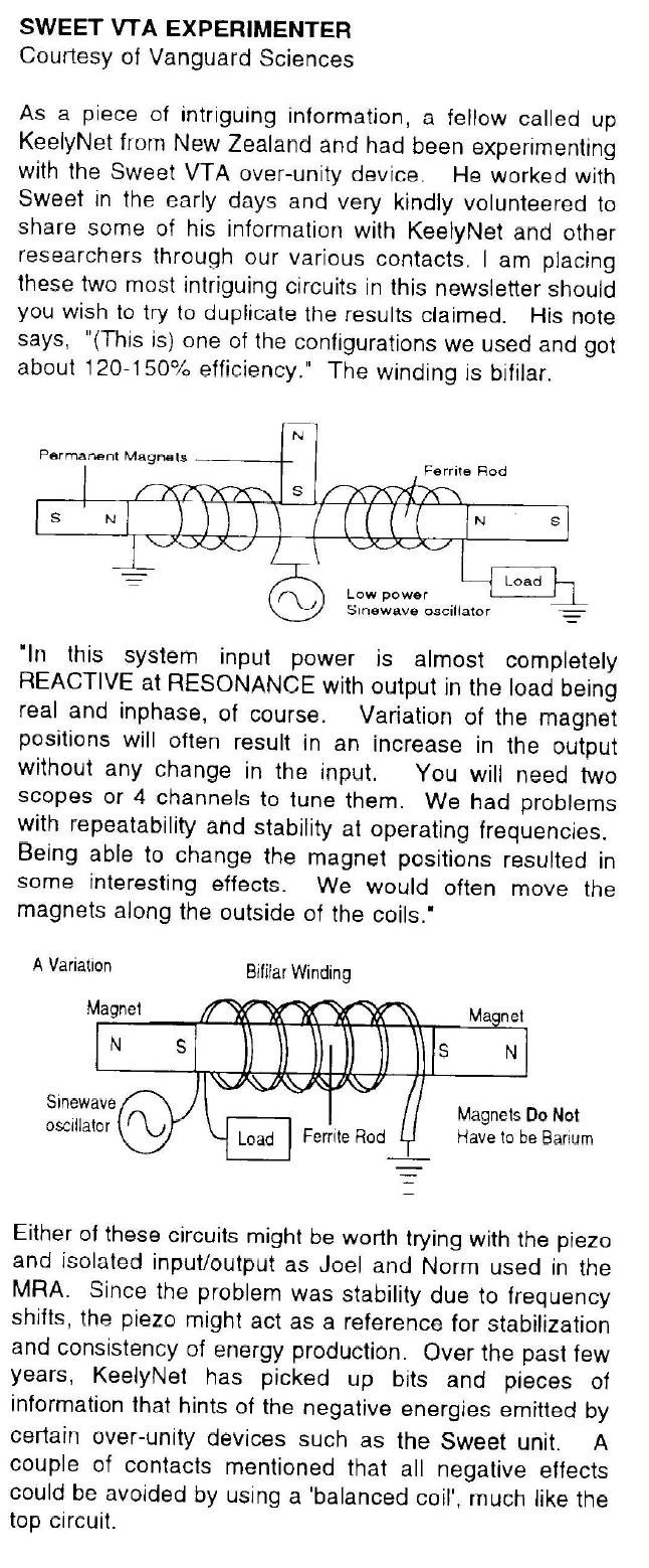
Magnetic Resonance is where the Currents in both Partnered Output Coils are 180 degrees out of phase. Equal in magnitude and opposite.
Alfred Hubbard, Floyd Sweet, and Don Smith used the term: Magnetic Resonance, or at least inferred it. Floyd sweet has this to say about it:
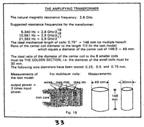
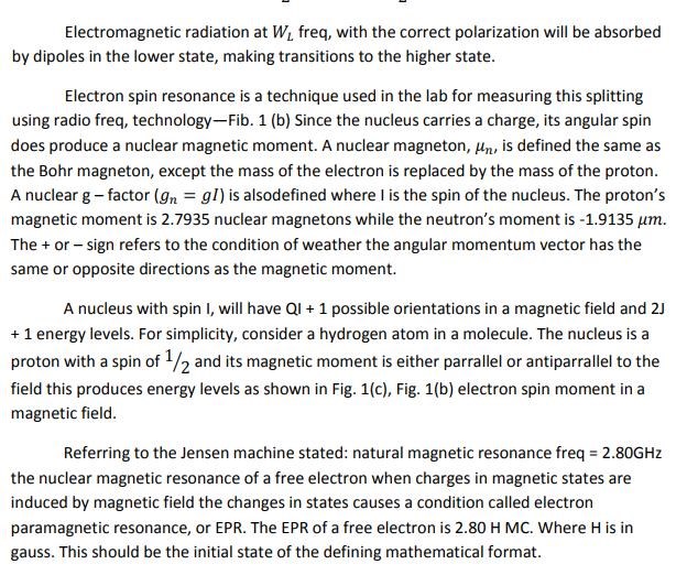
Natural magnetic resonance freq = 2.80GHz the nuclear magnetic resonance of a free electron when charges in magnetic states are induced by magnetic field the changes in states causes a condition called electron paramagnetic resonance, or EPR. The EPR of a free electron is 2.80 H MC. Where H is in gauss.
Alfred Hubbard gave us this insight:
Don Smith spoke of Magnetic Resonance all the time:
Useful energy occurs as the result of imbalances in the ambient background energy, which is a transient phenomena. In the electrical field, it is a closed system subject to heat death, which severely limits it's utility. The flip side of the electron, produces magnetic waves which are an open system, not subject to heat death. These waves, being unrestricted, are the universal source of energy when unlimited resonate duplicates from this one source are available. Therefore, the key to unlimited energy, is Magnetic Resonance. In order to understand this, requires putting a stake through the Heart of Antique Physics. Non-linear and Open Systems are universally available in Magnetic Resonance Systems, Explosions of any sort [including Atomic Explosions] and Combustibles of any type. Mechanical equivalents would be levers, pulleys and hydraulics. A highly obvious example is the Piano where the Key impacts the one note giving one sound level, which resonates with it's two side keys providing a much higher sound level. Magnetic Resonance Energy clearly amplifies itself, demonstrating more energy out, than in. Ohmic resistance does not apply to Magnetic Resonance which travels unrestricted for great distances, therefore multitudes of electrons are disturbed, and their back-spin translates magnetic into usable electric energy. The right angle component which the magnetic flux provides, translates into useful electrical energy. Taken at right angles, the Magnetic Dipole provides an unlimited source of electrical energy. The writer is recognized world-wide for his knowledge and experience. See his Web Site at altenergy-pro.com.
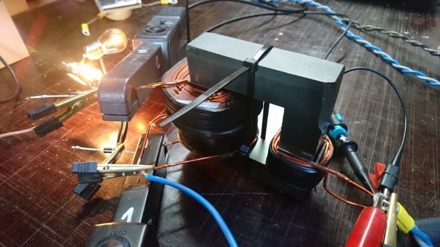
The Mr Preva Experiment shows us Magnetic Resonance:
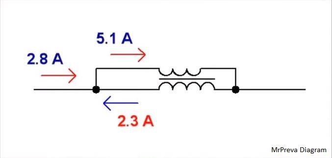
The Ampere Turns is equal to the Current I through Turns N, so 7 Turns times 5.1 Amperes = 35.7 Ampere Turns. The same is true for the second Coil, Current I through Turns N equals 11 Turns times 2.3 Amperes = 25.3 Ampere Turns. This is unusual, the ampere turns would normally be the same but we see quite a different figure, a difference of: 10.4 Ampere Turns.
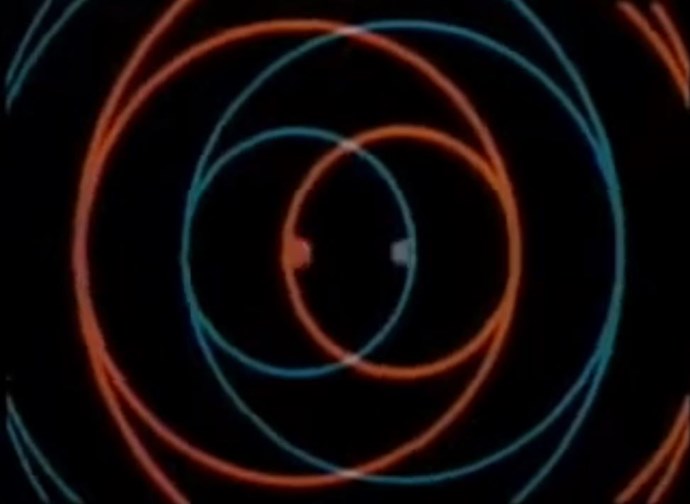
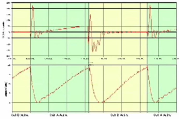
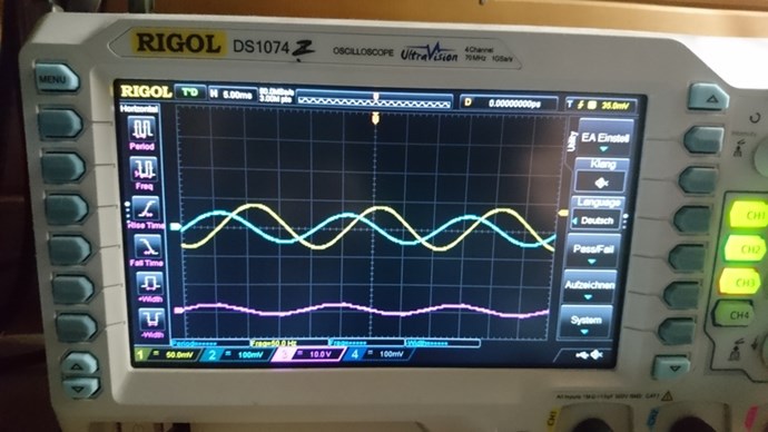
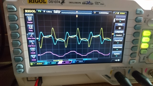
We see the Currents are 180 degrees out of phase, the Magnetic Fields are in Resonance:
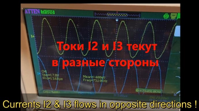
We can see, Magnetic Resonance is the bringing about by means of Circuit resonance of Magnetic Fields that are opposite, 180 degrees out of phase, and Magnitude are approximately equal.
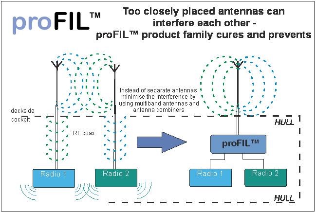
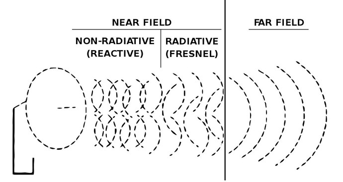
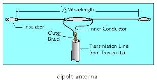
NOTE: Antenna Theory uses Magnetic Resonance techniques. We have covered this in great detail already.
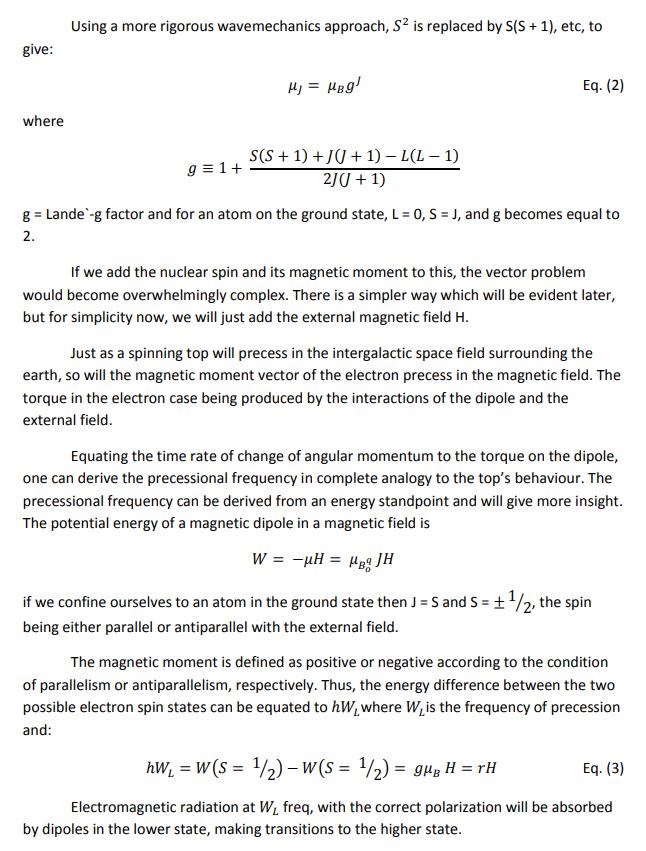
This Magnetic Resonance, does seem to be a quantum effect, Magnetic Moments of the Electrons precession like Spinning Tops in an external Magnetic Field.
Chris


 7 we repeat driving the meander


 .
.


 .
.


---open-tesla-research.jpg?width=20&crop=0,0,20,20)

