

Hello Friends, It occurred to me to post some lines regarding the measurements of Devices under Test, and want to invite all who are interested to discuss in this thread opinions, suggestions, techniques of measurements. Most Researchers know that testing of in and output power, COP and efficiency is an important tool when working on AU Devices, but also that it can be very tricky to achieve really reliable results. For this reason it would be helpful to elaborate the best possible convention for trustable measurement techniques and practice. Vidura
Measurements
- Topic Is Sticky
- 6.8K Views
- Last Post 02 November 2022


Chris
posted this
02 November 2022
- Last edited 02 November 2022
My Friends,
Bad Measurement Practice is rampant in the community, even by those that you may see working, and think are very impressive, they are mostly not skilled in the art, and with fancy words and lavish amounts of goulash, they swindle you from your end goal: Free Energy
Never forget:
There are those that work against us!
These people are employed to smear the field of Energy with Disinformation and Fakery!
It is up to you to learn the Best Measurement Practices, and apply them to the best of your ability!
Its up to you to make sure you are working on the right technology, which we here @aboveunity.com have shared and have many Independent Replications to show you the truth!
Your Scope Channel Zero Graticule Line is where you need to start!

Don't let them fool you with Bad Actor BS!
I see so much Disinformation and Fakery! It is disgusting to see!
Best Wishes,
Chris
- Liked by
-

-

-
-


scalarpotential
posted this
18 July 2022
- Last edited 18 July 2022
A bit offtopic, but since fusion was mentioned, it reminded me of this inventor that shows how to get fusion products in a combustion engine:
http://www.rexresearch.com/degeusboron/NL1030700.html
Listed patent WO0208787 is 100% similar to Stan Meyer's hydrogen fracturing.
- Liked by
-

-
-
Chris
posted this
14 July 2022
- Last edited 14 July 2022
My Friends,
This thread covers in great detail, why we should not be taking RMS Measurements on a DC Input Power! I want to re-iterate this fact, because we have had a situation on Jagau's Thread, where RMS was shown on each Channel.
Exactly as Jagau said:
It seems misunderstood that when we are in the presence of different waveforms the way of calculation is different
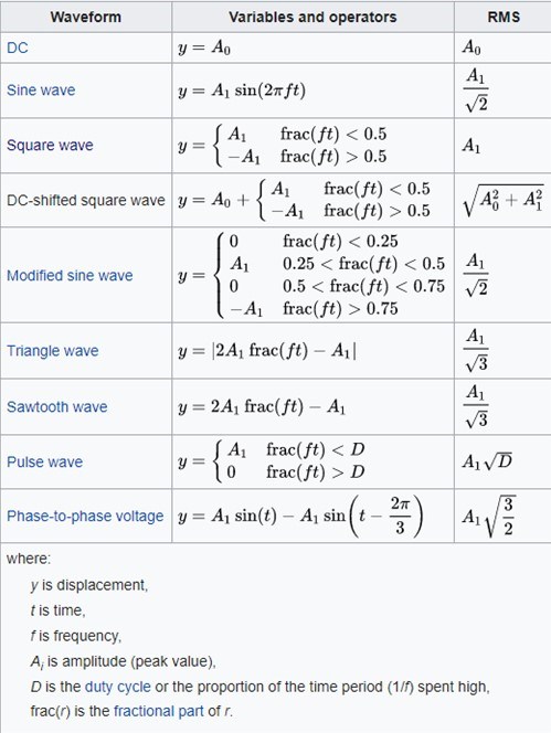
RMS Can not be used because all power on the line is counted as Input Power, active Power, used Power and this can be very different from the actual situation!
Why is this important? Watch this video:
Here is an example of why it can be very different: Using a Non-Linear Load on a DC Power Source
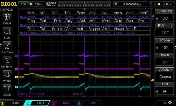
EG:
- 1.28 Watts RMS ⇐ Includes Negative Power: V x -! = -P
- 0.0957 Watt's Average ⇐ Only the Forward Power, Active or Used Power. If Negative, more Power is going back to the DC Source!
Power Flow in a Four Quadrant Argand Diagram:
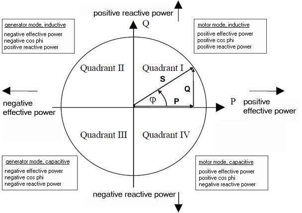
Its worth studding the Power Flow in the Four Quadrant Argand Diagram to see how this works. Again, Positive Voltage x Negative Current = Negative Power, Generator Mode!
Again, already covered, the V x I Power, if one does the math, can work out to be Negative, and RMS voids this Power! RMS Includes this power as Used Power when it is not!
Know what your Input is doing, and then you can make so much more progress! Ignore others that do not abide by Industry Standard Protocol!
We have the Best Measurement Protocols in the World! We are Accurate!
Bad or misleading procedure can cost you the Success you work so hard for, so learn Correct and Accurate Procedure, please!
Best Wishes,
Chris
- Liked by
-

-
-
-
- and 1 others
Chris
posted this
27 October 2021
My Friends,
Here are some videos I want to show you how confused Science is:
Fusion Reactors are SO INEFFICENT and SO EXPENSIVE to build and maintain, that one must ask why are they being pushed so hard and with such Blind Faith!
I believe Gravity Research is being done in these machines, and the public is not being told!
Best Wishes,
Chris
- Liked by
-
-
Chris
posted this
27 October 2021
- Last edited 27 October 2021
My Friends,
It seems Aboveunity.com's World Leading Measurement Techniques have now, all of a sudden, been adopted by others:
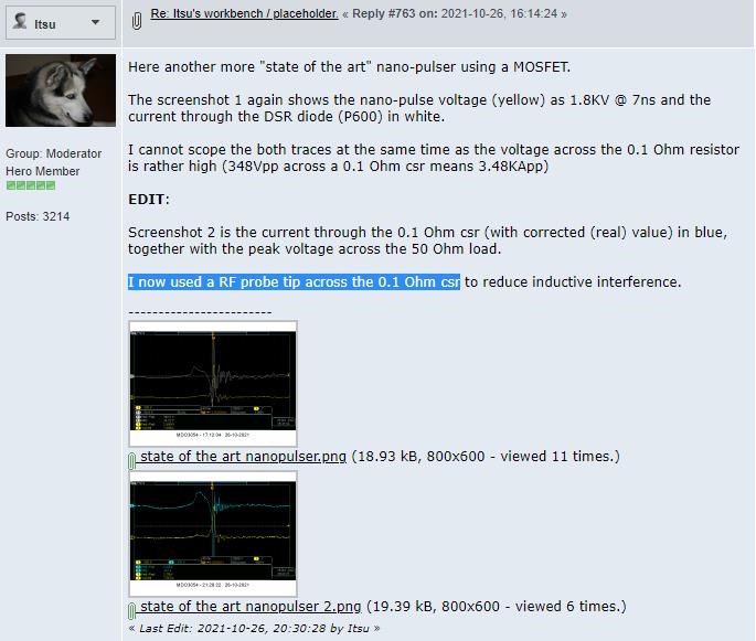
Ref: Itsu's "state of the art" nano-pulser
Those that used to try to call fault to Aboveunity.com's technique! Now use this very same Technique!
Isn't that Ironic! My how things have changed! Seems they have managed to pickup on Industry Standard Techniques, the ones we learned many years before!
If Itsu was measuring "Power", can anyone see a problem that Itsu would have in doing so? It is easy to spot!
Best Wishes and great to see the evolution of those that used to pick others work to pieces! See Here for details!
Chris
- Liked by
-
-
-
-
- and 1 others

raivope
posted this
26 November 2020
- Last edited 26 November 2020
Hi co-creators!
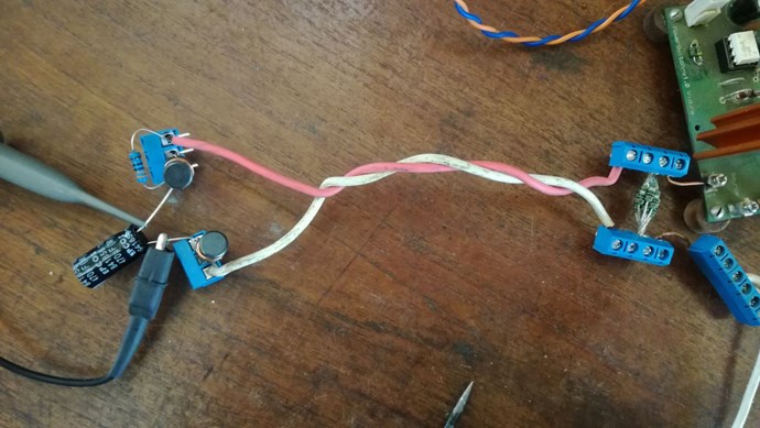
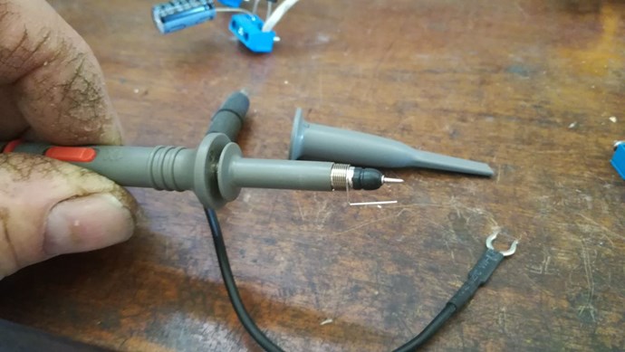
I found an amazing solution for current measurement by testing different shunts, resistors(10x in parallel), current clamp.
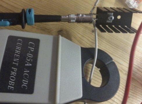
Lets call it HF shunt (above) and the bottom one is 200kHz bandwidth clamp (realistically you can go to 20kHz where you start having a phase lag).
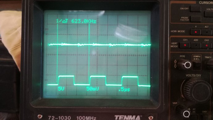
This HF shunt is virtually noise free and totally free from phase lag - tested up to 60MHz.
However, it will have some anomalous amplitude rise near 2MHz, so I would certify this shunt to have 1MHz bandwidth.
Only 3 pieces needed:
* Oscilloscope Probe, Passive, 150 MHz (run at 1:1) - https://uk.farnell.com/testec/lf312/probe-oscilloscope-low-frequency/dp/220619
* BNC Coaxial, Straight Jack, 50 ohm - https://uk.farnell.com/amphenol/b6251c1-nt3g-50/rf-coaxial-bnc-straight-jack-50ohm/dp/1111295
* Current Sense Resistor, 0.1 ohm, PWR220T-35 Series, 35 W, Thick Film, TO-220 - https://uk.farnell.com/bourns/pwr220t-35-r100f/resistor-power-0-1r-0-01-35w/dp/2101746
This Oscilloscope probe had special connector for BNC.
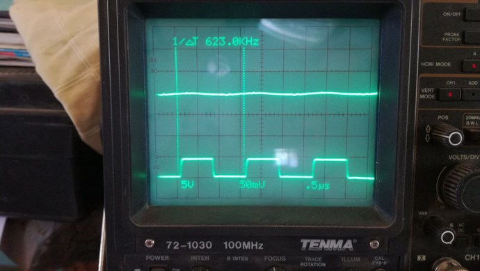
Here you can see the noise difference of this wire shunt you use and HF shunt:
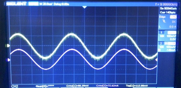
My top:
- HF shunt - 1MHz
- thru the hole wire shunt - 200kHz - the same as 10x 1ohm metal-foil resistors in parallel (less noise than wire shunt)
- CP-05A current clamp - 20kHz (good point to have it is low noise and galvanic isolation)
Best wishes,
Raivo
- Liked by
-
-

-
-

- and 1 others
Chris
posted this
21 November 2020
- Last edited 22 November 2020
My Friends,
It is true, some totally ridiculous statements are being made over on one of the Other Forums. You know where!
I want to stress again, use: Common Sense
Take a length of Wire, 3 Centimeters, it has an inductance of 300 μH, we remove 2 Centimeters of Wire and replace this length with a Current Sensing Resistor, or Current Shunt, it has an inductance of 200 μH, which just happens to still give us 300 μH in Total.
Are we Better off or Worse off?
Neither! We have the exact same Inductance!
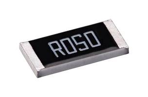
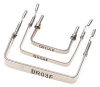
Some people absolutely Grasp at Imaginary Straws! Current Sensing Resistors come in all Shapes and Sizes, with many different Inductances and Resistances! Here are just a few examples:
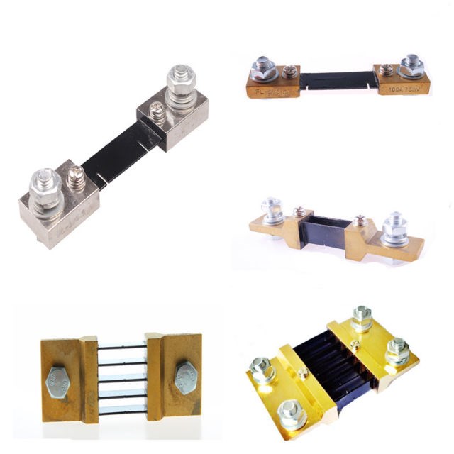
If someone is Un-Educated enough to choose a Current Sensing Resistor that has a large Inductance in Applications at High Frequencies, then this is a mistake!
However, as already pointed out, if your Current Sensing Resistor has no more Inductance than a piece of Wire of the Same length, then you are ONLY going to have a problem if you have not followed advice already given, which is: Keep all Wire Lengths as Short as Possible.
It is a total joke, just stupidity, to make any wild claims of:
- In Accuracy
- Current Waveform Difference
- Bad Data in General
Unless one has deliberately chosen bad Current Sensing Equipment! E.G: Wire Wound Resistor or similar!
It is obvious, the Current in a Circuit, MUST always be the same in the Circuit, the Entire Circuit, according to Kirchhoff's Current Law:
We simply can not read different Currents at each of the different Meters, or Nodes! That is, unless the Element itself is creating a Change in the Current! E.G: An Active Element!
Those people, out there, should know this already, unless they are Learning Impaired! Alas, they don't! And that's why you should not listen to them!
It simply can not be said, a Sense Resistor with the same Inductance as a piece of Wire the same Length will be any more problematic than the piece of Wire itself! That's just not true! Period!
The Comparison being made by these people is ridiculous:
All people with 5c of Common-Sense is not going to use L1 as a Current Sensing Resistor!
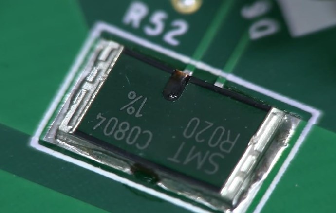
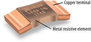
This Current Sensing Resistor:
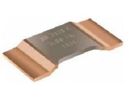
Has: < 3nH that's less than 3 Nano Henry's of Inductance. Less than some pieces of Wire, the same length! See Datasheet Below.
We have covered this many times:
Again, do stupid un-educated things, expect stupid un-educated Results!
Best Wishes,
Chris
- Liked by
-

-
-
Chris
posted this
20 November 2020
- Last edited 21 November 2020
My Friends,
I have decided to post this post here in the Measurements thread also, to help others out.
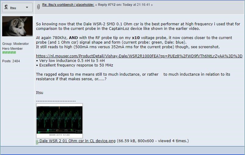
Itsu has a fresh round of "Surprising" data:
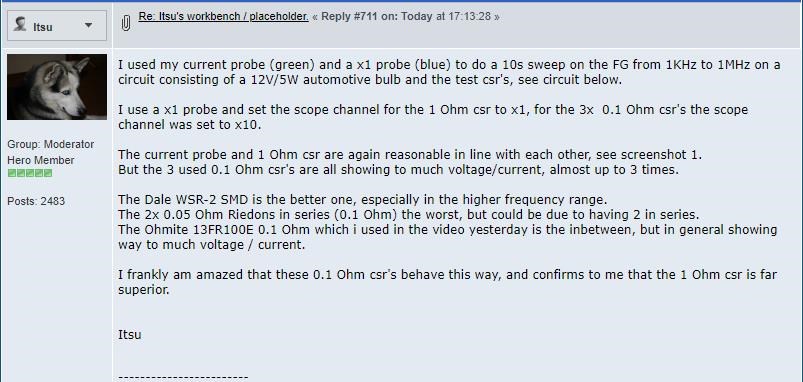
Ref: Itsu's workbench / placeholder.
This is an astounding series of statements! It really is!
Every single Engineer on the planet will disagree with Itsu's statement that a 1 Ohm Current Sensing Resistor is Superior!
Proving Incorrect
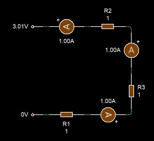
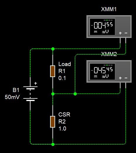
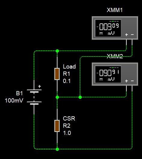
In the following circuits, you can see the Voltage Drop across the Load and the Current Sensing Resistor:
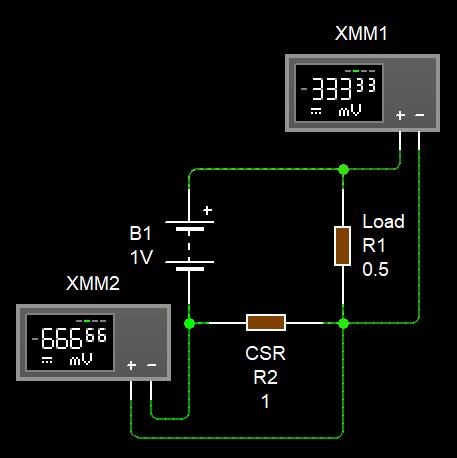
You can see, with a 1 Volt Supply, with a 0.5 Ohm Load, we get a greater Voltage Drop across the 1 Ohm Resistor than the Load, this means, more Energy is being wasted in the 1 Ohm Resistor than is being consumed in the Load!
This Circuit, because we introduced the 1 Ohm Resistor is now Mal-Performing by a factor of: 2
This circuit is NOT being measured properly, because we have changed the Circuit by introducing 2x In-Circuit Impedance is not greater than the Load!
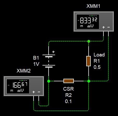
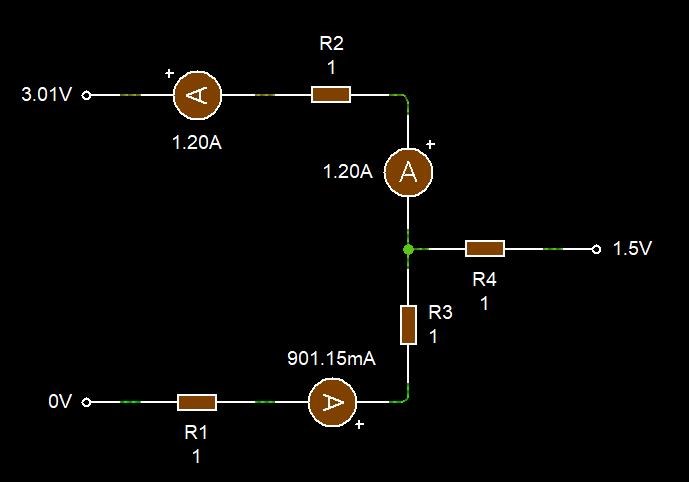
This Circuit, because we introduced the 0.1 Ohm Resistor is now Mal-Performing by a factor of: 0.2, an improvement of 10 times!
Now we can say we have reduced the In Circuit Impedance by 10 Times and also have a Circuit that is MUCH Closer to the actual way the Circuit is supposed to actually work!
It is Best Practice to measure a Circuit, with minimal Introduction of Impedances!
Current Sensing Resolution
How does Resolution work?
The Voltage Drop over a Resistor is using the Ohms Law equations to determined Current via: I = V / R
NOTE: Current Sensing Resistors are ideal at specific Ranges of Currents! Beyond those Ranges, they are not adequate and should be replaced with adequate Resistors!
As far as I understand, 50mV per division is Industry Standard Baseline for Noise test. So anything below 50mV per division is not useful for accurate Measurement.
People must think about this! This is important!
If we plot, the Voltage Steps vs the Current we see something that is very important:

The deviation between the 1 Ohm Resistor and the 0.1 Ohm Resistor grows linearly, this means, the Error is greater per Voltage Step, on the 1.0 Ohm Resistor! Yes, Error!
For every 50mV step, which is mA if on has the Scope set correctly, is: 10x
What does this mean? Well, we are able to Measure much more finely, we can Measure, 10mA to 1mA, let me show you:
There you have it, the Resolution is much greater on the 0.1 Ohm Resistor than the 1 Ohm Resistor, we lost a whopping: 45mA compared to the 0.1 Ohm Resistor: 4.5mA. So you see here, we have 10 times the Resolution with a 0.1 Ohm Resistor! 10 Times More Accurate! Simply: 0.1 Ohms is 10x the Resolution of a 1.0 Ohms Resistor!
A Resistor is a Resistor is a Resistor
NO! You need to carefully select a Resistor to do the Job! The exact same waveform should always be available every single time between the Resistors, except for the above stated Resolution issues! If the waveform is in any way distorted, throw away the Current Sensing Resistor and get a Good One!
We have very carefully selected the 0.1 Ohm 1% Tolerance, Metal Strip Through Hole Resistor to accurately give measurements in median Current Ranges! Others can try to find fault all they like, but really, they just show how un-educated they are about such things!
A good Current Sensing Resistor should be nothing more than a piece of Wire of Known Impedance. Remember, keep all wire lengths short as possible! Always!
Conclusion
I hope you can see, why we are Light Years ahead of the other Forums! This, what I have shown here is simple stuff and they should know this stuff!
It is Industry Standard to use Very Low Resistance Current Sensing Resistors! This is very well known! Extremely Low Resistances, even as low as 0.0001 Ohms, or 100 μOhms.

I recommend all to do their own research and even check and double check what I say!
Rigol DP832 Precision Power Supply Current Shunt Resistor: 0.02 Ohms 1% Tollerance
The top of the line Keysight Current Probe uses a 0.1 Ohm Sensing Resistor! Thanks Jagau for the link!
Don't let yourself be led up the Garden Path, is easy, if you let this happen!
NOTE: This group of people that have been calling: "Measurement Error", on your machines for decades! Do you see why I have done what I have done? They are not qualified, or well enough educated to make Judgment on Others Work!
Stick to Facts, Logic and what Makes Sense!
Best Wishes,
Chris
- Liked by
-
-
-
-
Chris
posted this
19 November 2020
- Last edited 19 November 2020
My Friends,
In our quest to bring easy simple measurement to every person with an Oscilloscope, we have had a few issues that have cropped up, simple issues to fix, but issues one needs to be aware of.
Best Practice: It is always best practice to use a Current Sensing Resistor ( CSR some use the term CVR Current Viewing Resistor ) that will have the least possible effect on the Circuit! As if the CSR was not in the Circuit! Remember, you always want to take measurement on the Circuit , which means if you change the Circuit by introducing large Impedances, the Circuit is no longer the same! To take accurate Measurements, the Circuit must be minimally affected by introducing your Measurement Equipment! This is important!
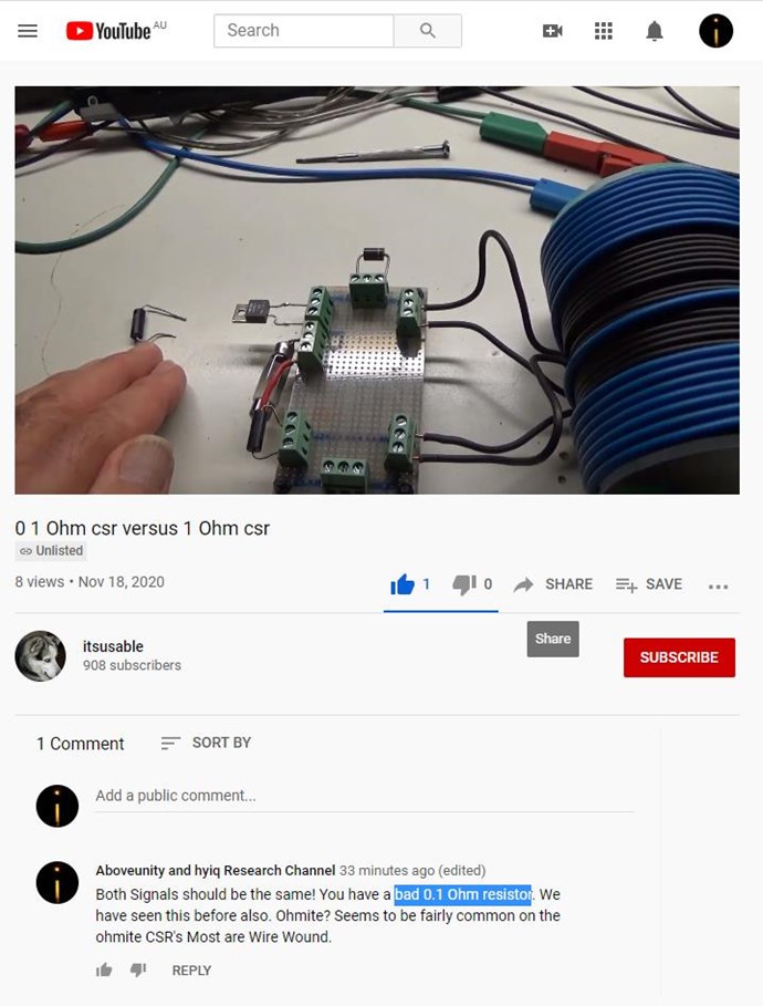
Recently, Itsu has done a video on 1 Ohm vs a 0.1 Ohm resistor:
For sure, the 0.1 Ohm Resistor is Bad!
Ohmite Resistors are commonly Wire Wound, they say that they are not, or say: "Non-Inductive" but beware, they can go bad very easily!
CD_Sharp has seen this issue before and we have resolved this simply by replacing the Resistor.
This is another reason Equipment should always be Calibrated and Checked! We have not yet seen any issues with the Measurement Block I have shared with you all! The Measurement Block should always give you a solid stable Signal! However, it is wise to Test its accuracy on a regular basis!
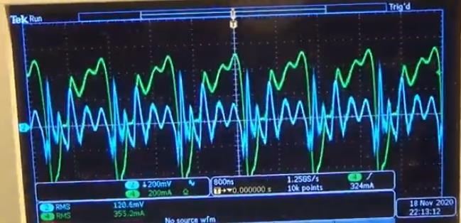
Where:
- Green Trace = Clamp on Current Probe.
- Blue Trace = 0.1 Ohm Current Sensing Resistor.
Current Signals should always be the same! If they are not, as in Itsu's case, above image, there is a Problem!
I have left a Message:
Best Wishes
Chris
- Liked by
-

-
-
Vidura
posted this
19 September 2020
- Last edited 19 September 2020
Hello,
In this post I will address another potential issue on measurements , which you won't find likely on any other Forum. On order to establish a really complete and trustworthy measurement protocol we have to be aware of the following effect. It is not explained by conventional EM theory. I have already posted something about it, but can't remember in which thread. It is documented in the videos
and
I could observe the effect in the following circuits, it happens when the core goes in the nonlinear region near or beyond saturation:
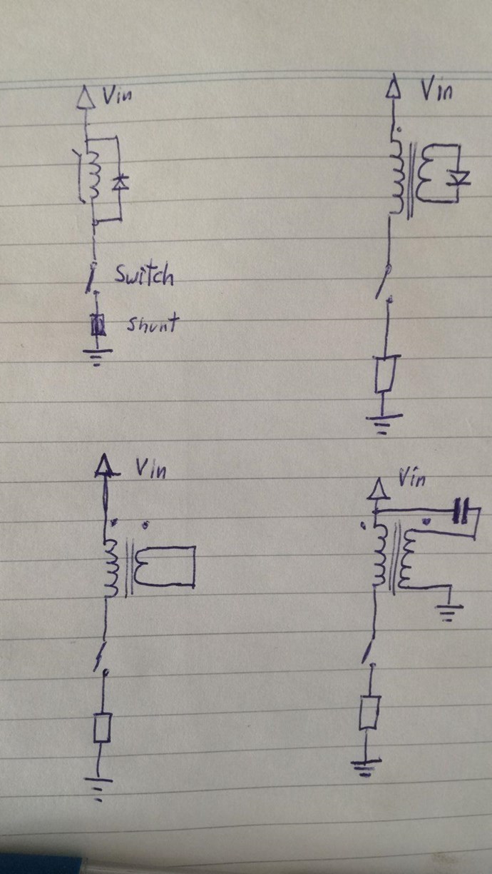
The most pronounced in the first one, where the core saturates always beyond a threshold duty cycle. In some cases it occurs only with a very fast switch, and the intensity might vary with various parameters. One most important is the physical length of the shunt, it's material and the distance of test point and scope ground connection. So here I have made a short video related to the effect on measurements:
Some recommendations regarding your measurements specially when in the DUT saturation or nonlinearity are likely: If you find some odd behaviour like currents against blocking diodes, or switches in off state, then check again using a different shunt, eventually carbon resistors, ensure that the scope probe is close to the shunt resistor(test point and ground, both).
Vidura
- Liked by
-
-
-
-

- and 5 others
Vidura
posted this
18 September 2020
Hello Friends,
In this post I will provide a solution for the interference issues shown in the last post. Note that this method is adequate (only) for quantitative measurement, that is for power measurements. It consists in averaging the signal from the shunt (for current) or from other test points (voltage). Note that this method will provide a clean signal, but will not account for the involved powerfactor. Thus it is suitable for resistive loads only.
Up to frequencies of 50khz we can do it as simple as this:
Also the analogue meters are very simple and trustworthy, if some decoupling capacitors are placed near the DUT.
In the following Images you can see how I developed a simple filtered circuit to make clean avarage measurements:
at lower frequencies the above circuit works fine.
But when we increase...
so i tried this:
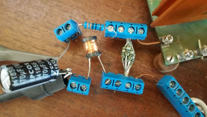
Much better, but not good enough.
next step....
the result, at maximum frequency of the PWM:
the remaining interference comes from the conector of the scopeprobe:
removed the ground clip:
Now it is acceptable. I hope this helps some.
Vidura
- Liked by
-
-
-
-
- and 4 others
raivope
posted this
17 September 2020
Hi,
For 0.001 ohm shunts, I have built, the op-amp must be chosen with very low offset error to have quality output. Plus and minus supply to op-amp must have good RC filter to avoid ripple noise.
(I used to build amp sensor plus multiplied by voltage we get power and power was forwarded (in range 0..5V) galvanically isolated to output where you can read with ADC or simply with panel meter. Usually I kept 2.5V as a zero centre to measure also negative range.)
Best,
Raivo
- Liked by
-
-
-
-
- and 4 others
Chris
posted this
17 September 2020
- Last edited 17 September 2020
Hey Vidura,
My Friend, you are exactly correct! Thank You for Sharing!
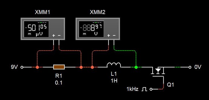
For very low Resistance ( 0.001 Ohm or lower ), a Op Amp may be required, depending on how much Current the Resistor carries, as the Scope may not be able to accurately measure such low Voltage Drops:
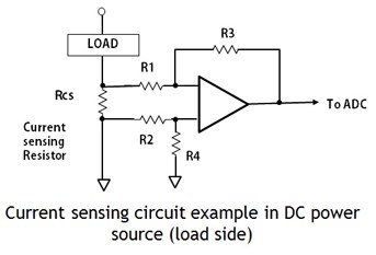
NOTE: ADC is Analog to Digital Converter. A Microcontroller uses a ADC to read the Voltage Drop in a Digital Meter.
None of this is hard, if others that are not sure, just follow the advice of those of us, here, that know better and are trying to help.
Selecting a Resistance Value is important for the Range of Currents you expect, just as Vidura has said.
Your Guide is very valuable! Thank You!
Best wishes, stay safe and well My Friends,
Chris
- Liked by
-
-
-
-
- and 4 others
Vidura
posted this
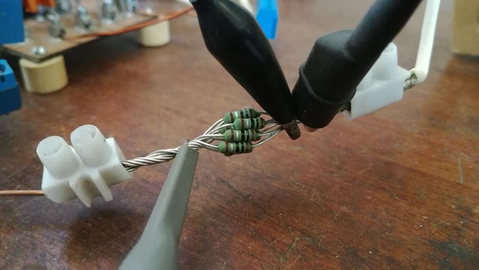
17 September 2020
A couple of things more: I haven't tested special nonconductive shunt resistors, as I don't have any available, they might be something more accurate . The best performance gave the bundle of precision resistors. For the practical implementation of shunt resistors we should choose the value In proportion to the expected current in the circuit. It has to be taken in account that the power dissipation of the shunt will increase at the square of the current, therefore for major current capabilities, shunts of very low resistance and high wattage will be employed. For example a shunt 0.001Ohm@ 100A will dissipate 10watts , and read 0.1V For more accurate measurement at lower current, the resistance should be increased. A 0.1ohm shunt rated for 10W would be capable up to 10A Reading 1V on the scope. This ratings are for the maximum amount of CONTINUOUS current, with pulsed current the value can exceed, dependent on the duty cycle. For measurement of small current in the mA range a 1ohm resistor could be a good choice, as the higher voltage reading will reduce noise on the scope.to be continued...
- Liked by
-
-
-
-
- and 4 others
Vidura
posted this
17 September 2020
Hello All,
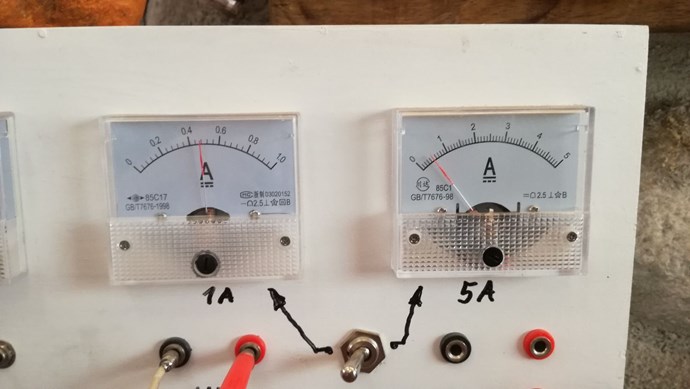
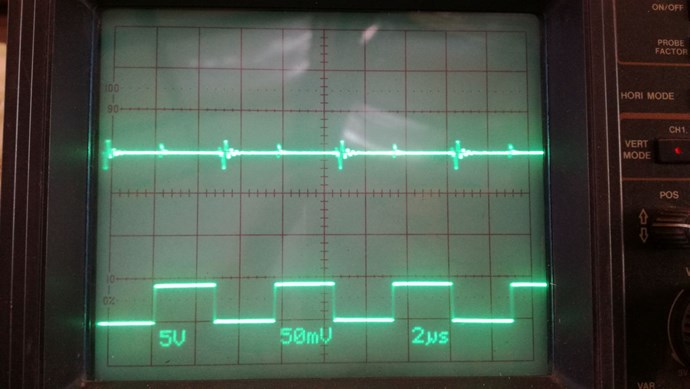
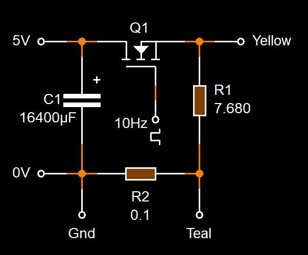
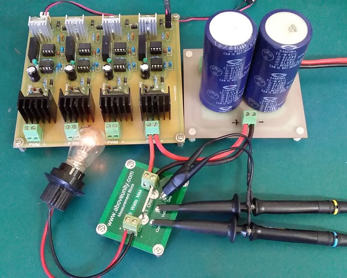
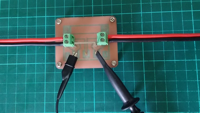
as there has been some uncertainty regarding the current measurements with the scope, I decided to make a series of tests with different shunts and test conditions. The circuit is simple, a low side switch, IRFP460 , a filament bulb 12V 20W, two capacitors on the supply line 10000uF + 100nF. PWM module set at 50% duty cycle.
.jpg?width=690&upscale=false)
the analogue Ammeter showed the expected average value of 1/2 peak current in all the tests:
.jpg?width=690&upscale=false)
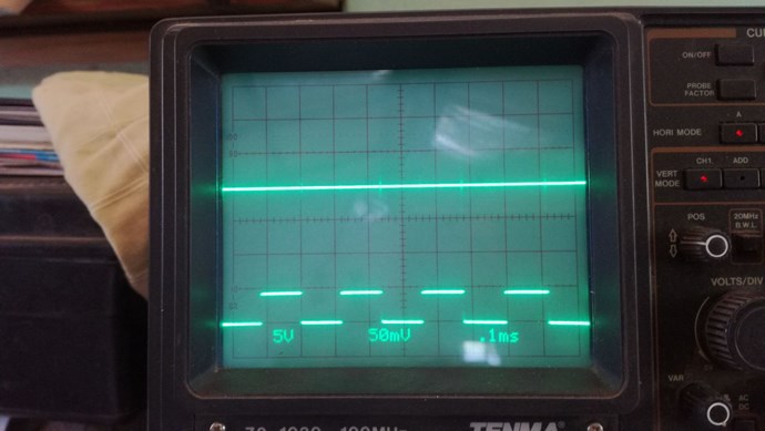
The first test is made with a wire wound 1 ohm 5 W resistor. I really expected a much worse result with this one, but note that the inductive part isn't significant as the "coil" has only 4mm diameter and 10 mm length, with bigger sizes we can expect more inductance of course. here the scope shots in three different frequency ranges:
.jpg?width=690&upscale=false)
.jpg?width=690&upscale=false)
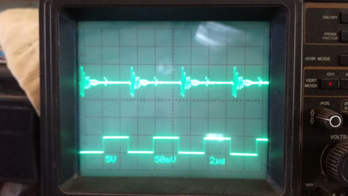
above 30khz switching spikes appeared.
.jpg?width=690&upscale=false)
@ 100khz notable ringing and large switching spikes
.jpg?width=690&upscale=false)
at 350khz ringing and alteration of duty cycle.
.jpg?width=690&upscale=false)
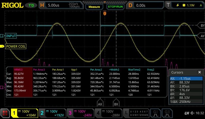
next tests with a boundle of 10 resistors 1 ohm 1% equivalent 0.1 ohm.jpg?width=690&upscale=false)
less ringing and smaller spikes
.jpg?width=690&upscale=false)
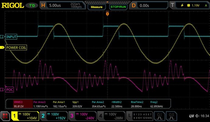
at 350 khz also a lot of distortion and ringing, but I realized that a lot of it is caused by the parasitics of the layout and wires.
.jpg?width=690&upscale=false)
I added a 100 nF cap near the shunt and the signals improoved notably:
.jpg?width=690&upscale=false)
.jpg?width=690&upscale=false)
.jpg?width=690&upscale=false)
A selfmade SS rod shunt:
.jpg?width=690&upscale=false)
.jpg?width=690&upscale=false)
At higher frequencies unsuitable.
.jpg?width=690&upscale=false)
metalstripe 0.1 ohm:
.jpg?width=690&upscale=false)
.jpg?width=690&upscale=false)
conclusion, for the instance non of the tested shunts would give a reliable readings above 150khz, using the math function of a scope. will continue.
- Liked by
-
-
-

-
- and 3 others

Jagau
posted this
14 September 2020
- Last edited 14 September 2020
Hi Chris
Analog device a very reputable semiconductor company and their service engineer produced a memo which you confirm Chris.
Read the pdf enclosed as irrefutable proof.
It is the average power that produces the correct value, and thus it is average power that has physical significance.
Jagau
- Liked by
-
-
-
-
- and 1 others
Chris
posted this
14 September 2020
- Last edited 14 September 2020
My Friends,
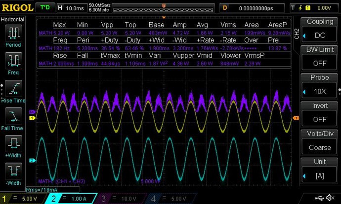
A simple experiment, lets see if we can take a simple experiment and learn something simple?
The Circuit:
The Scope Shot:
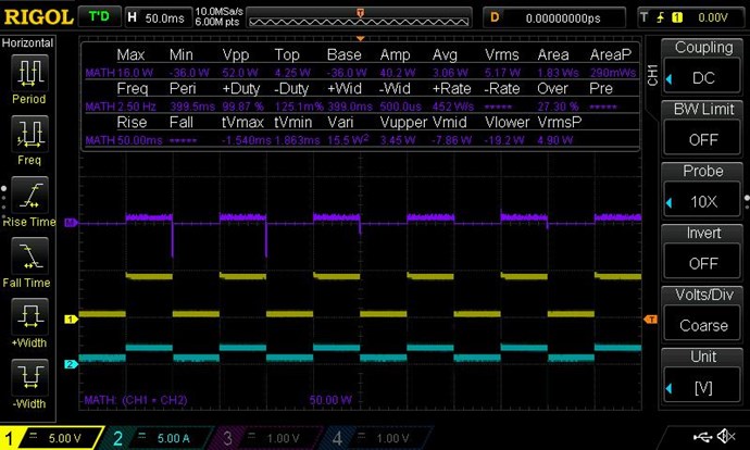
The Results:
The power used, is the Average: 3.06 Watts, but the RMS: 5.17 Watts, Power is a long way off!
Using DC, Switching on the High Side, and measuring the Input Power, going to the Resistor, or Globe, we see a massive difference! A difference that the other Forums have not even switched on to!
2.11 Watts of Error!
I have to say, the professionals that so many people have listened to for so long, over on the other Forums, are so far out of touch its just not funny! They are completely Wrong on nearly every aspect!
I hope all Aboveunity Members can now see why I have tried to tell everyone not to use RMS? When using DC, Switched, RMS is not sufficient to give anywhere near accurate measurements!
You must use Average, or Mean, on the Input!
The smallest Experiment can yeild the most important information!
Best wishes, stay safe and well My Friends,
Chris
- Liked by
-
-
-
-
- and 4 others
Jagau
posted this
13 September 2020
Hi baern
Its look like what EEvblog spoke about this rigol model MSO
Known Firmware Bugs / Issues 11 Time base bugs
look here:
https://www.eevblog.com/forum/testgear/review-rigol-mso5000-tests-bugs-questions/
Jagau
- Liked by
-
-
-
-
- and 2 others

baerndorfer
posted this
12 September 2020
- Last edited 12 September 2020
hi guys, here you can see a measurement from MSO5204
you will notice, that the measurement for the pulsewidth is not correct. the device switches between nanoseconds and microseconds for some reason. the cursor measurement is correct.
what i want to point out is, that we should not fully trust our equipment  it helps in many situations but only the operator who knows about how measurement is done correctly can derive meaningful theses out of it.
the next scope shot is for entertainment only...
greetings!
- Liked by
-
-
-
-
- and 2 others
Chris
posted this
30 August 2020
- Last edited 30 August 2020
My Friends,
Some so called measurement experts call the old fake news line: "measurement error", in reality, they are mostly wrong and can not correctly and accurately call "measurement error". They just don't have enough data and experience to make this call!
NOTE: Run a Scope Calibration before running important Measurements: Utility -> Down Arrow -> Self-Cal
Remember: Our Energy Machines are Non-Linear Energy Machines! They need proper protocols!
The following procedure is the basic procedure for the Rigol Oscilloscopes:
On the Output, RMS Measurements should be used. On the Input, Average should be used.
Mean is the same as Average.
Sampling, best to use the default: Normal, or use: High Res.
Setup the Probe Units, set V and I for the probes. Then hit the Math button, go to Math, set A x B, set operation: On, then set Source A and B to the channels you have set.
Set V and I for the Probe settings. Current on 10x on the scope, and 1x on the probe, for Voltage 10x on the scope and 10x on the probe.
Now go to Measure Button, set Measure all: On, and go to Measure All Source, set Math as the measure ticked.
At this stage, you should have a scope menu and it should be displaying Math in purple. You should have three Scope traces, Chx, Chy, and Math.
Turn on your DUT, and tune, adjust the Time and Division scales to fit all trace data, take measurements, screen shotting the Menu onto a USB Key plugged into your scope by pressing your Print Button. Then upload to the forum, this will give you a complete screen shot of the Scope Display.
Basic rule of thumb, Mean or Average is Forward Power minus Backward Power = Mean used Power. Remember, if 1 Amp + -1 Amp = Zero Amps, so forward Power can be the same as Backward Power, meaning if all your Power comes back to you, then you have used no power!
On the Output, RMS is used, as all Power Out is Used, so no Power is going back to your Input.
I have a short video on how to take measurements using the Rigol Oscilloscope.
Note: I have shown the basic setup for most measurements, using the Aboveunity.com Measurement Block using a 0.1 ohm metal strip resistor.
Don't let anyone else tell you you are wrong! You must only measure Used Power, Returned Power is not Used Power on the Input, so you MUST use Average and not RMS!
On the Output, You need to use RMS and compare it to the Average!
The procedures on this thread are very important and need to be understood and followed to make Close Approximations!
It is very easy for Experts, to make wild assumptions and for those not skilled in the Art, to become confused, a tactic they rely on to dissuade others, thinking they have it wrong when they do not! Let no one tell you any different especially when they have Zero Real World Experience!
Only Aboveunity.com Members should be trusted in this Field! No one else!
Best wishes, stay safe and well My Friend,
Chris
- Liked by
-
-
-
-
- and 4 others
Chris
posted this
04 August 2020
Hey CD,
Thank You My Friend! I have found these simple things extremely useful!
Best wishes, stay safe and well,
Chris
- Liked by
-
-
-
-
- and 1 others
Chris
posted this
25 June 2020
My Friends,
Most of us, here know this already, but because I though they were done so well, I thought I would post them here anyway:
I did a similar thing some time back and although it was very useful, its only good to a certain frequency. Ideally, DC Projects are what these are best for!
Best wishes, stay safe and well,
Chris
- Liked by
-
-
-
-
Chris
posted this
26 May 2020
- Last edited 26 May 2020
My Friends,
Some mostly constructive debate is occurring here: Partnered Output Coils - Builders Group - Moderated!
Note, there are no real Builders, not like here! The debate is on measurements, this the reason I put this post in this thread. Some posts from the one I linked to on are very beneficial if you wish to brush up on our existing knowledge.
Others, on the other forums have been doing it wrong for a very long time! No wonder they are chasing their tails!
Best wishes, stay safe and well,
Chris
- Liked by
-
-
-
-
Chris
posted this
12 March 2020
My Friends,
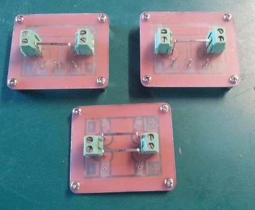
Vidura is right! There are plenty of things that can throw measurements off! Thermal Drift, to Stray Inductance, to a scope probe set incorrectly.
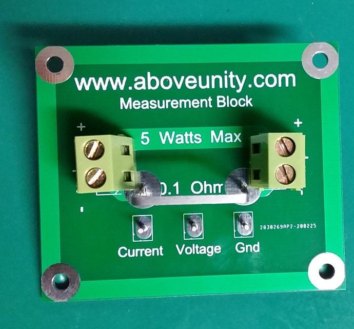
The Measurement Blocks I am selling use Industry Standard 0.1 Ohm accurate to 1% Through Hole Current Sensing Metal Strips, very accurate and very reliable:
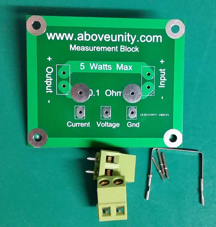
These PCB Kits are the product of years of experience, a product of on going reliability. This method is one of the most accurate methods of measuring power that I have every used for the price. Other accurate methods can cost many thousands of dollars, I show in this video just how easy it is to use:
See the thread: Measurement Block PCB and Kit on E-Bay for info on how to purchase.
Keep your cords short, wires short and there is be very few problems you need to watch out for! Stray Inductance is one of the worst!
It is always good to test and verify what your'e doing, always calibrate your scope and watch for thermal drift.
Best wishes
Chris
- Liked by
-
-
-
-
Vidura
posted this
12 March 2020
- Last edited 15 September 2020
Hello All!
this post in order to make you aware of the unusual behaviour of current shunts with a certain length, when tests are performed ,which involve partially or total core saturation. In some videos titled "the effect of core saturation " I have shown already this strange effects. I was not sure if it was something specific of the analogue scope , but lately I saw the effect on one of CD-sharps videos, on his DSO.
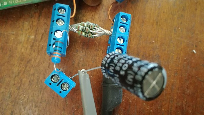
in this experiment he used as current shunt two metal strip precision resistors series connected. I recently made a test on a saturable device with this shunt:
and then y changed it for this bundle of 10 1ohm resistors(=0.1ohm):
Under "normal" conditions the stainless steel rod shunt is very accurate, but when a saturated core is present, it showed more than 5x the value of the resistor bundle. So when we are working with this kind of devices, the length of the shunt seems to be a critical factor. I also noticed this readings when I used a current transformer, but I have no data about professional current probes, as I dont have such tools. If someone has these, it would be interesting to make a comparison test , if there are inconsistencies.
Mostly I wanted to post this to avoid you to run in measurement errors, using for example the metal strip resistors, when there is a possibility to reach the saturation area of the core.
Vidura.
- Liked by
-
-
-
-
- and 1 others
Jagau
posted this
19 January 2020
- Last edited 19 January 2020
Another way to take a voltage measurement anywhere in a circuit. In differential mode with an oscilloscope,
try it out the friends it works very well
only with the 2 channels nothing else.
Jagau
- Liked by
-
-
-
-

- and 2 others
Chris
posted this
19 January 2020
- Last edited 19 January 2020
Atti is right!
A precision Resistor will be one of the best investments you can make! Get a 0.1 Ohm Precision Resistor, makes for easy Current Monitoring!
A precision Resistor, one with minimal Inductance, ±1% or so is important!
Worth going to have a read of this thread: Current Observation and Measurement
Chris
- Liked by
-
-
-

Atti
posted this
18 January 2020
It annoys the length of the measuring resistor I use. That's why I'm buying a precision resistor. We'll see.
"Four-wire resistor optimized specifically for the small-ohmic range. Separately wired sense connectors avoid measurement error caused by transient resistors. Particularly useful in power electronics."
https://www.conrad.hu/hu/precizios-ellenallas-pbv-01-ohm-447331.html
- Liked by
-
-
-
-
Chris
posted this
24 December 2019
- Last edited 24 December 2019
My Friends,
This post is in regard to recent posts on Fighters Thread, The ZPM, specifically the set of posts after this one.
I see a lot more confusion entering at the moment than is necessary! The introduction of Mains Metered, Low Bandwidth, Watt Meters and Input Power Circuitry was the topic.
No matter what the Circuitry is, in regard to the input Line and the Power Source, and as I said, the less the better, the circuitry will play a role in what occurs on the Input Side, being the Circuitry is Input side Circuitry.
Lets break this down to the most basic possible logic:
Your Input power Line:
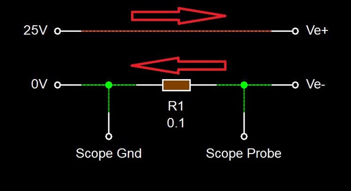
NOTE: This is Conventional Current, we know the opposite actually occurs in the wire. I am showing Conventional Current so as to not confuse people.
Every single soldier, Charge, that marches up one Wire, must march back down the other Wire. Meaning Current, a bunch of soldiers
From 25V at the Top Left to Ve+, then through the load, not shown, and back again, from Ve-, Right to Left to 0V. Completing the loop. Not a single soldier is lost, with respect to the Circuit!
This is DC, or Direct Current. Directly from one Terminal to the other Terminal. If the Direction of this Direct Current Changes, and this Change is not a function of the Power Supply, supplying the Power, then some or all, or in some cases more soldiers march back the other way.
If 100 soldiers march the Circuit, but 10 come back, then we have not used the 100 soldiers, we only use 90 soldiers. We have a 10% return on our Input Power, not all Input Power is Consumed. This concept appears to be very difficult for many EE's to grasp! Current is NOT Power, but Voltage x Current in a DC situation, is.
E.G:
- 25 Volts x 100 soldiers, or amps = 2500 Watts.
- BUT, we had 10 soldiers come back!
- 25 Volts x -10 soldiers = -250 Watts
So, we used 2500 + -250 = 2250 watts, 250 watts less than was initially thought!
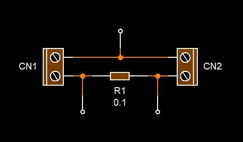
IMPORTANT: Not a single unit can be lost, with respect to the Circuit, every single unit must pass through R1, the Current Sensing Resistor or CSR, sometimes a Current Viewing Resistor CVR. This means all Current from the Source to the Load, and all Current from the Load to the Source can be observed flowing through this CSR, R1.
IMPORTANT: The Bandwidth of this measurement system is only limited to the Oscilloscope and the Current Sensing Resistor you choose to use.
Merry Christmas Everyone!
Chris
- Liked by
-
-
-
-
- and 2 others
Chris
posted this
16 December 2019
- Last edited 16 December 2019
My Friends,
Vidura has provided some very important insight! As has Atti!
Complex Signals are a problem for many Instruments - However, an Oscilloscope is designed to measure these signals. Of course, that's the entire design specification for the Oscilloscope.
We should expect from every single Oscilloscope: If it can be drawn on the screen it can be measured.
However, this is not always the case!
We should, as Atti pointed out, try to aim for a DC to DC Input to Output measurement! Thus smoothing out the complex Waveform we might be missing for accurate Scope Measurements.
If there is real power there, then it should be able to fill a Capacitor, then power a Load.
I want to share some helpful videos I shared on Tier II:
Both very good videos and help to understand how the Scope takes a measurement.
The Oscilloscope is by far the most advanced Instrument we have ever created to measure waveform's!
We Should not, we can not discard it as one of the most useful tools in our arsenal! If we are going to do this, we only need to learn how to use these tools properly!
We must not fool ourselves! We must investigate everything and do it properly!
Chris
- Liked by
-
-
-
-
- and 1 others

Atti
posted this
15 December 2019
- Last edited 15 December 2019
Hey Vidura.
You touched the point again.
I share the view that digital meters should only be used for orientation. Or DSO.
If there is something strange, you have to think about the possibility of moving on. Or why the situation happened.
But the exact definition requires the ratio of dc input to dc output.
No more accurate than that.
It is possible to deceive others, to mislead others.
But if I mislead myself, then something is wrong.
This can or may not be accepted.
The point does not change.
I think.
- Liked by
-
-
Vidura
posted this
15 December 2019
Hi Friends Some thoughts about interferences and noise. Certainly All who do experiments can observe this phenomenon in some cases. How does this impact on measurements? As you might know i don't own a DSO, and my old ctr scope don't have math functions to make measurements of complex wave forms, so I can only use my common sense to evaluate the influence of interference, ringing and so. We can have the case of a "real" ringing in a setup or device, which would of course display actual voltage and current on a scope, and count as actual power. If this power can actually be used to drive a load is another question. But there's also another case, where interference appears in the measurement device, meters or scope, not displaying the actual behaviour of the DUT. I have many times observed that all kinds of digital meters became practical useless, due to interference. Of course a DSO should be mostly immune to this as it is intended bas precision instrument. I have noted that this interferences are special notable when we have devices which develope standing waves, or with partially saturated cores, shorted coils(also half cycle with diode), and hi voltage Oscillating E fields. In a conclusion of my experiences the analogue meters are the most trustworthy ( not the multimeters, the simple versions). It is a good idea to put them in series to the PS , so you always have a comparison and will nota mayor deviations immediately. For the moment I believe that a backlooped device is the best proof to be AU. Regards Vidura.
- Liked by
-
-
-
-
- and 1 others
Atti
posted this
08 October 2019
Hi everyone.
For measuring Vidura inductance.
We can see that there is a short circuit between two identical coils
after insertion of iron, the inductance of one of the coils increases.
The magnetic field closure of the coils will be shorter.
They will also be more independent.
Thus, a distinction is made between the flux closing in the iron and the flux of the coil.
If it is no longer able to close in iron (due to saturation), it will close in the air. Or iron in between the two rolls.
- Liked by
-
-
-
-
- and 2 others
Jagau
posted this
08 October 2019
Yes indeed Vidura
it is still a very good question that I had already asked and if it can help. I have read a lot of interesting things here.
I believe in this forum we can make good exchanges of ideas between each member.
I like this forum.
Jagau
- Liked by
-
-
-

-
- and 2 others
Vidura
posted this
08 October 2019
Thanks Jagau, This helps, for air coils it seems to apply also. Vidura
- Liked by
-
-
-
-
- and 2 others
Jagau
posted this
08 October 2019
- Last edited 08 October 2019
Hello Vidura
may be an answer to your question with exemple,
look at page 56 of the pdf published recently:
The resulting inductance of a single layer powdered iron toroid can not be precisely predicted due to the effect of leakage inductance, (uncoupled flux). The further apart the turns are, the lower the resulting inductance will be due to reduced flux linkage between turns
Jagau
- Liked by
-
-
-
-
- and 3 others
Vidura
posted this
08 October 2019
Hello Friends, I Wang to present here a simple test i did , maybe anyone can help to verify if we can trast the LCR measurements, or if this results can be bached up with calculations. I took a lenght of wire 12 meters and connected the inductance meter first with the extended wire:
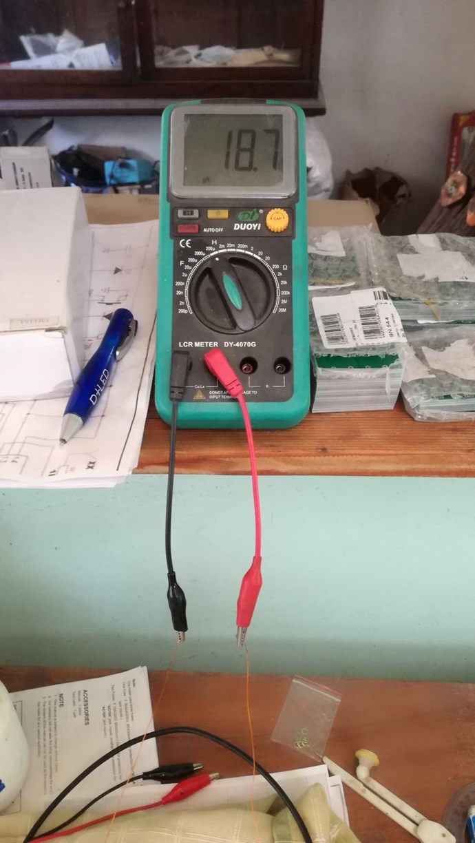
reading 19,7 uH
then with 75 turns on a plastic former, in all tests the same wirelenght:
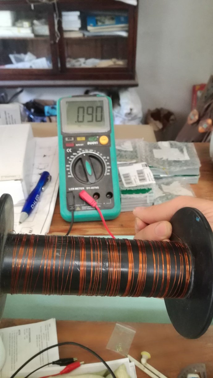
the coil is extended over 20cm lenght, reading:90uH
now the lenght is reduced to 4cm:
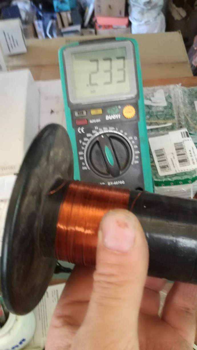
reading 233uH
the lenght is further reduced:
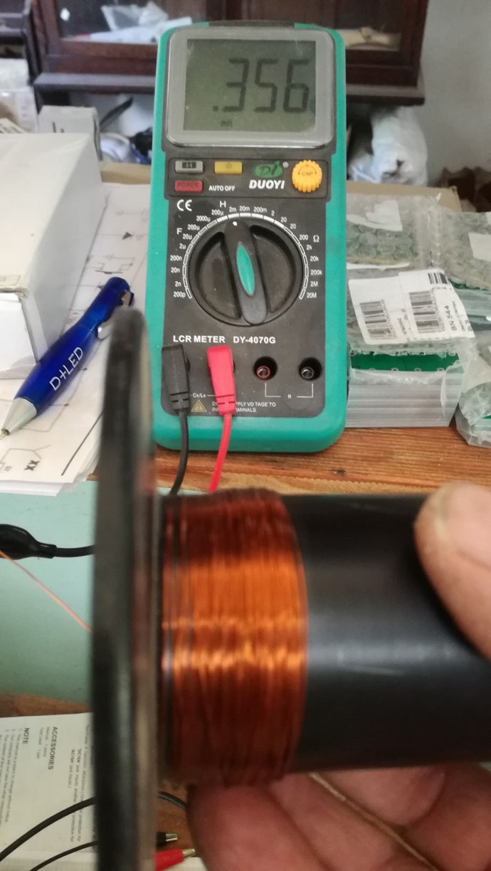
Reading 356uH
now the last on a smaller former with 145 turns in 6 layers:
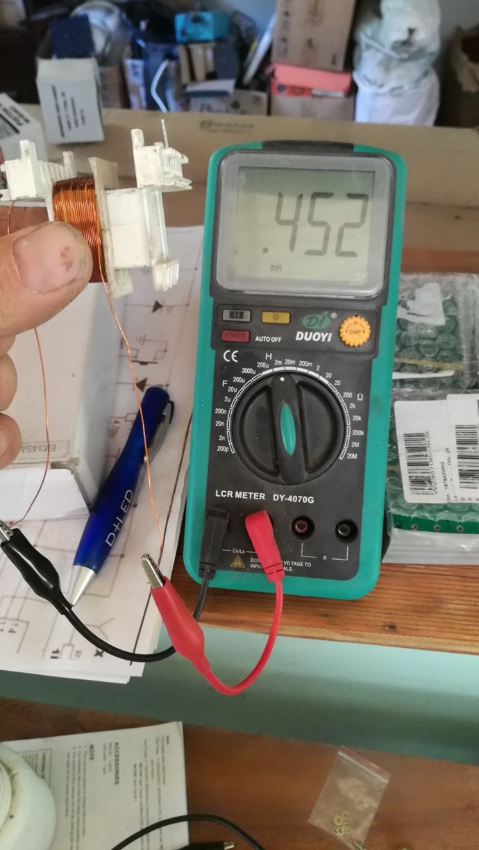
Reading :452 uH
I did this tests just out of curiousity, but now i have some doubts on the measurements, or what formulas would mach this results,
regards Vidura
- Liked by
-
-
-
-
- and 4 others
Vidura
posted this
12 September 2019
Hello Friends,
here i will post about an odd result when i was measuring the signal current feeding the opt isolated driver of the Power Switch Modules. In the video you can see the comparison when using the PWM module and then the SG. The scope probes are connected for voltage ch1 (5V/div) and current across a 1 ohm resistor ch2 (10mV/div). the frequency is 30khz 50% duty cycle in both signal sources. Here is the Video:
If someone can check if other SGs also show the same effect would be helpful.
Regards VIDURA.
- Liked by
-
-
Chris
posted this
11 September 2019
My Friends,
For the historical record, we have some conversation over on: Current measuring using non-inductive resistors
This is so we can keep track of posts that flip flop between threads.
Chris
- Liked by
-
-
-
Atti
posted this
10 September 2019
Vidura. Szép munka .
CD. Unfortunately, I have a similar problem.
- Liked by
-
-
-
-
Vidura
posted this
10 September 2019
I have made a test of the simple circuit suggested by Chris, and want to remark a couple if things: in any circuit where a switch abruptly is turned on and off there will occur transient spikes, the magnitude depending on parameters like the parasitic inductance and capacitance , voltage , current and frequency. Note also that incandescent lightbulbs have a spired filament, which at high frequencies will have considerable inductance, and high power Leds have a lot of parasitic capacitance. One thing I noted , and can not be explained convincedly with the above mentioned influence, is that the shorter the duty cycle becomes the higher the switching transient spikes. I would guess that the ether environment is stroked harder by very short pulses, but this will be subject of another topic. here the video:
Vidura
- Liked by
-
-
-
-
- and 3 others
Vidura
posted this
10 September 2019
- Last edited 10 September 2019
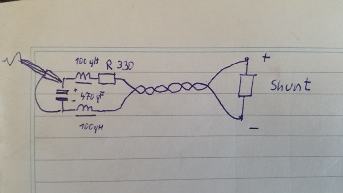
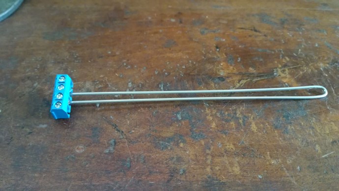
Hello All
Here I will show you how you can make a low cost precision shunt resistor 0.1 ohm made from a 1.6mm 308 grade stainless steel welding rod. First cut a length of 299mm of the rod, 291 mm corresponding to 0.1 ohm resistance, plus 4mm each side for the screw connectors:
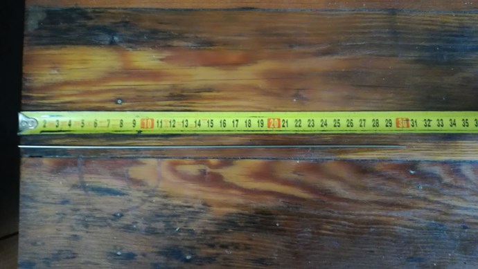
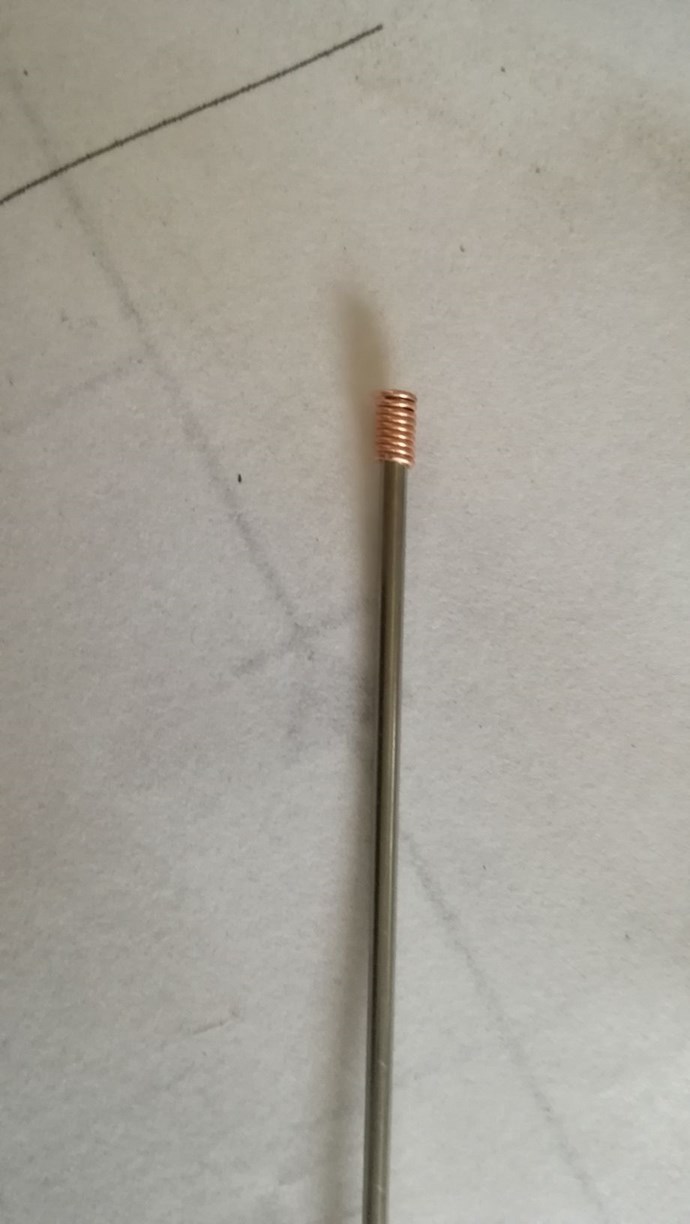
Then wrap several turns of a uninsulated thin copper wire over the 4mm reserved for the connector on each side. This is very important, because if only a small area of the resistive rod is touching the connector, the resistance can increase notably and lead to erroneous results.
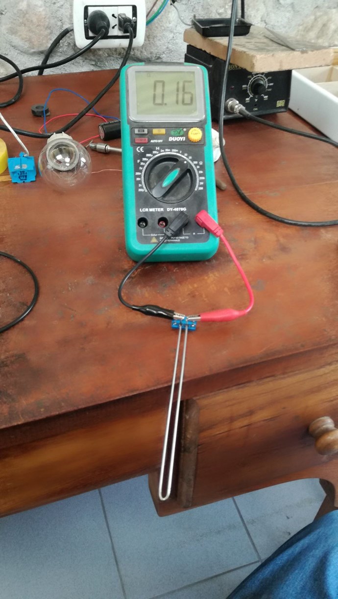
Then bend the rod in the centre exactly to get a U shape like this:
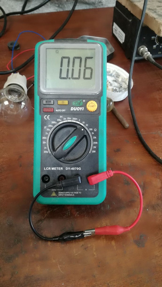
And finally mount it tightly on a screw connector :
- Liked by
-
-
-
-
- and 3 others
Chris
posted this
10 September 2019
Hey CD,
If I may remind you of our thread: On and Off, Conduction in a Mosfet
We looked at properly switching a Mosfet. This should help greatly with your problem.
I hope this helps!
Chris
- Liked by
-
-
-


solarlab
posted this
10 September 2019
- Last edited 10 September 2019
Hi CD Sharp,
** Jagua's more than likely correct. **
Might be MOSFET jitter or oscillation due to Gate bounce or noise - the MOSFET is being turned on - off rapidly due to gate trigger threshold being exceeded (noise - probably created by feed-back from the drain - source switching side).
Refer to some FET gate driver application notes for details.
JMHO of course... [but, I'd bet that's what it is  !]
!]
SL
- Liked by
-
-
-
-
- and 1 others
Jagau
posted this
10 September 2019
it is a very good idea to use gate series resistors of 1K to 10K.
This is especially important if the Gate signal comes from another circuit board.
If a MOSFET could be left floating then use a pull down resistor (100K to 1M is generally ok) from Gate to Source.
you will avoid many problems like this one.
Jagau
- Liked by
-
-
-
-
- and 2 others

Fighter
posted this
10 September 2019
- Last edited 10 September 2019
I would suggest to replace all the inputs and outputs of the device plus the connection from the signal generator to the MOSFET driver with thicker multifilar wire like I use (you can see it in my photos).
Links:
Don't forget all those coil wires I see intersecting each other are producing high-frequency and powerful enough magnetic fields interfering with each other. That could be the source of the ringings, those coil wires are forming themselves small coils interacting with each other.
The only ringings should come from the device itself.
Just my opinion.
- Liked by
-
-
-
-
Chris
posted this
09 September 2019
Well, CD, this is odd!
I am going take a guess and say bad Mosfet, perhaps stray capacitance on the Gate? You truly should not be seeing this, even with wire wound resistors!
Testing both Resistors, do you get the same results?
To me, this just does not look like the Resistors are causing all this noise! It is coming from somewhere else, perhaps even a bad connection in the breadboard?
Upwards of 3 to 10 MHz you might see noise like this, but not this low! 1KHz!
Chris
- Liked by
-
-
-
-
Vidura
posted this
09 September 2019
- Last edited 09 September 2019
Hey Fighter, Yes this shunts are also ok, the stripe shape has very little inductance , a drawback might be the small resistance, depending of course on the measured current., This one will have a voltage drop of 7.5mV @1A. You can test them with DC, although they are factory calibrated. For practical reasons and easy reading without calculations it is recommended to use values like 0.1 ohm,(100mv @1A) or 1ohm (1v@1A)for smaller current values. Vidura.
- Liked by
-
-
-
-
- and 1 others
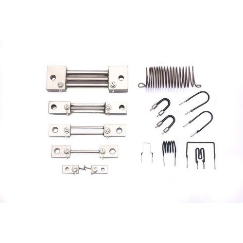
Fighter
posted this
09 September 2019
... or something like this ?...

They are 10A/75mV shunts and I intend to use them for real-time and permanent measuring system on ZPM's input and output.
I will try to use them with some analog ampere-meters, the only problem is calibrating this system to make sure the measurements are accurate all the time in any conditions...
- Liked by
-
-
-
-

We're Light Years Ahead!

Our Above Unity Machines:
Recomended Protocol:
Members Online:
No one online at the moment
What is a Scalar:
In physics, scalars are physical quantities that are unaffected by changes to a vector space basis. Scalars are often accompanied by units of measurement, as in "10 cm". Examples of scalar quantities are mass, distance, charge, volume, time, speed, and the magnitude of physical vectors in general.
You need to forget the Non-Sense that some spout with out knowing the actual Definition of the word Scalar! Some people talk absolute Bull Sh*t!
The pressure P in the formula P = pgh, pgh is a scalar that tells you the amount of this squashing force per unit area in a fluid.
A Scalar, having both direction and magnitude, can be anything! The Magnetic Field, a Charge moving, yet some Numb Nuts think it means Magic Science!
Start Here:
Message from God:
Hello my children. This is Yahweh, the one true Lord. You have found creation's secret. Now share it peacefully with the world.
Ref: Message from God written inside the Human Genome
God be in my head, and in my thinking.
God be in my eyes, and in my looking.
God be in my mouth, and in my speaking.
Oh, God be in my heart, and in my understanding.
Your Support:
More than anything else, your contributions to this forum are most important! We are trying to actively get all visitors involved, but we do only have a few main contributors, which are very much appreciated! If you would like to see more pages with more detailed experiments and answers, perhaps a contribution of another type maybe possible:
They REFUSE to tell me why!
The content I am sharing is not only unique, but is changing the world as we know it! Please Support Us!
Thank You So Much!
Browse by Category:
Weeks High Earners:
-
Chris
190
-
 FringeIdeas
22
FringeIdeas
22
The great Nikola Tesla:

Ere many generations pass, our machinery will be driven by a power obtainable at any point of the universe. This idea is not novel. Men have been led to it long ago by instinct or reason. It has been expressed in many ways, and in many places, in the history of old and new. We find it in the delightful myth of Antheus, who drives power from the earth; we find it among the subtle speculations of one of your splendid mathematicians, and in many hints and statements of thinkers of the present time. Throughout space there is energy. Is this energy static or kinetic? If static, our hopes are in vain; if kinetic - and this we know it is for certain - then it is a mere question of time when men will succeed in attaching their machinery to the very wheelwork of nature.
Experiments With Alternate Currents Of High Potential And High Frequency (February 1892).
