Parametric Excitations of Electric Oscillations

  • Topic Is Sticky
  • 3.2K Views
  • Last Post 09 January 2022
Chris posted this 09 August 2017

This thread is based entirely around the very old document, 1934, from Russian Researchers: "ON THE PARAMETRIC EXCITATION OF ELECTRIC OSCILLATIONS"

This document is attached below, in two pdf's, the original and a Translated OCR'ed by myself document also.

I want to include a snippet from the document, it is an example used in the document: Page.3, second paragraph.

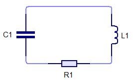
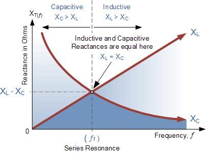
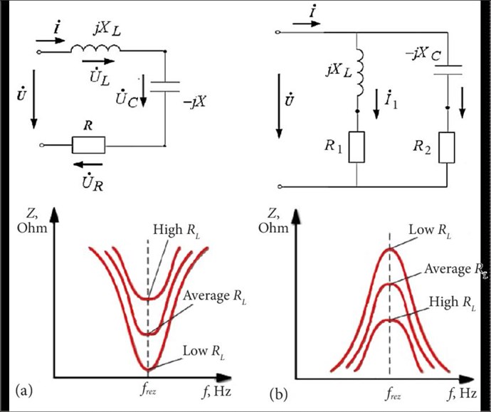
Suppose that a current i is flowing in an oscillatory system consisting of a capacitance C, ohmic resistance R, and self-inductance L, at some instant of time which we shall take as the starting instant.

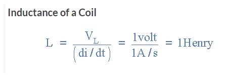
At this moment we change L, by, ΔL, which is equivalent to increasing the energy by 1/2  ΔLi2 The system is now left to itself.

After a time equal to 1/4 of the period of the tuned frequency of the system, all the energy transforms from magnetic into electrostatic.

At this moment, when the current falls to zero, we return the self-induction to its original value, which can evidently be done without expending work and again we leave the system alone.

After the next 1/4 period of resonance oscillations the electrostatic energy transforms fully into magnetic and we can begin a new cycle of variation in L.

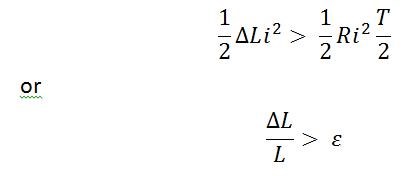
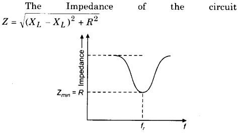
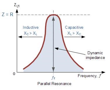
If the energy put in at the beginning of the cycle exceeds that lost during the cycle, i.e. if


where ε is the logarithmic decrement of the natural oscillations of the system, then the current will be larger at the end of each cycle than at the beginning. Thus, repeating these cycles, i.e. changing I with a frequency twice the mean resonance frequency of the system in such a way that

we can excite oscillations in the system without any emf acting on it, no matter how small the initial charge. 


I think we have seen now, many times, the importance of such Timing. The Timing Thread, we cover such phenomena! This with the MrPreva Experiment, it is a key component in the steps forward.

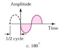
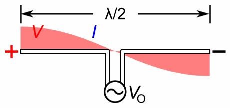
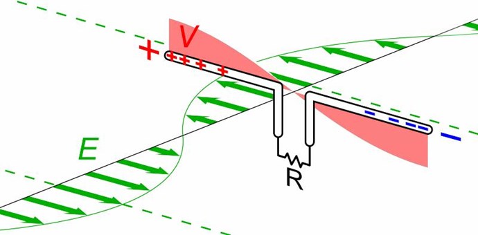
Energy is changing in time! Energy is entirely Electrostatic Energy (Red), Charge from the Capacitor discharges into the Coil for 1/4 of the Cycle, and then, Magnetic Energy (Green) is converted by the Coil back into Electrostatic Energy filling the Capacitor, on the second 1/4 Cycle:


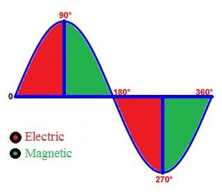
So, the Capacitor discharges its potential Charge, entirely into the Coil, then the Coil, because it reverses polarity, discharges its Magnetic Field back into the Capacitor. Thus the opposite Sine for the Charge Polarity. I have covered this in some detail in the: A Coil, the Current and the Voltage Thread.


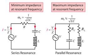
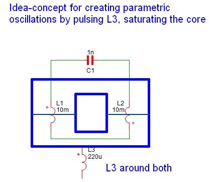
Below, an example of how Energy is added to the system by changing a parameter:


Parametric Oscillations can have two forms:

  • autoparametric excitation
  • heteroparametric excitation

Each with Regeneration (an external Voltage/Current Source) and without Regeneration.


Its very interesting to read the documents provided, it is a job to absorb it however! Much is complex, but not all of it needs to be understood!

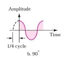
Its worth noting: 1/2 the Resonant Frequency, or Twice the Resonant frequency is one of the optimum point. This could be seen as:


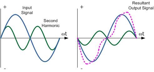
You can see, at 1/4 cycle, the sine of the second harmonic changes. Thus the Opposing Coils, Opposing Magnetic Fields.

Dynamic Magnetic Field Interactions, it is mentioned in the same document:

Thus a linear system cannot serve as an A-C generator.

Thus, as we have covered, this is the reason a "Common-Mode Choke" is good at its job, but nothing else.

We need a Dynamic System, Non-Linear in its operation, or Asymmetrical in its operation, not the same at the same time!

This is why we see Graham Gunderson's switching at near peak Current (Green Trace):


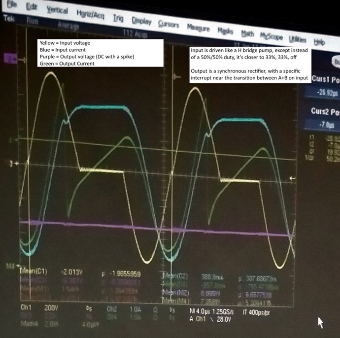
Because, this is where we need to change the Inductance, as he has.

   Chris

Attached Files

Order By: Standard | Newest | Votes
Chris posted this 09 January 2022

Hey Scalarpotential, 

In the thread: Non-Linear Inductance we saw that Inductance L = ε / di / dt

Where ε is the Back E.M.F, restricting the Current Flow, created by the change in Current that produced the E.M.F.

Reactance XL and XC in an LCR Circuit is about as Reactive as a Circuit can be, thus the Q Factor = 2 π f L / R and 2 π f L = XL  which is the Reactance, and R = Resistance.

However, in a Series Resonant LCR Circuit, Reactance XL and XC, Cancel:


In a Parallel Resonance LCR Circuit, Impedance is at Maximum:

It is well known:


In the Thread: Reduced Impedance Effect we saw Experimentally, that the Coils Resistance R can be the only Limiting Factor in a Coils Flow of Current: di / dt which is equal to the Inductance L.

Ref: Inductance of a Coil

Where: L is the inductance in Henries, VL is the voltage across the coil and di/dt is the rate of change of current in Amperes per second, A/s.

InductanceL is actually a measure of an inductors “resistance” to the change of the current flowing through the circuit and the larger is its value in Henries, the lower will be the rate of current change.


This has nothing to do with Saturation.

We learned that it is very easy to change, Up or Down, the Impedance of a Coil, due to Magnetic Field Interactions, which Changes the Inductance also!

Best Wishes,

   Chris

scalarpotential posted this 08 January 2022

There's a wiki now: https://en.wikipedia.org/wiki/Parametric_transformer

So V=L.di/dt becomes V=i.dL/dt

  • Liked by
  • Chris
  • Augenblick
Himrael posted this 15 October 2020

  • Liked by
  • Chris
  • Augenblick
raivope posted this 15 October 2020

Hi!

Here is my idea how you could change the core saturation (2x C cores) with L3 that is wrapped around all the setup.

(Capacitor and coil values are not important)

So far, I do not know any good (free) simulator where you can model the core saturation this way.
And had no time to test this concept, so I posted it here. It is just a concept!

[Edit]
Idea behind of parametric modulation is that you have two independent references of a nonlinear system: one thru induction (LC) and one thru saturation. They will not "add up" but multiply (modulation). 

So where we put a load? Load can be put on LC, switched on LC, in series with LC.
Also, theoretical-philosophically speaking - if you have no load/dissipation - then you will have reactive/generative response. Any system you have (POC, single phase or 3-phase system) that when you omit the load - energy has no dissipation - will phase shift and return to source. Provided that this system is negentropic/asymmetric. Aha! Then you can have H-Bridge inverter and feed back (overcharge) the bus (or battery) or directly to the grid.

Further ideas:
If you pulse L3 you can have inductance in series for ensuring more constant current, so that the secondary will not affect primary current.
Better yet, if you have two of those circuits, it will resemble more like a magnetic amplifier. A practical connection from one LC will modulate the input coil and the other system is a mirror, so like yin-yang.

Best,

Raivo

  • Liked by
  • Chris
  • Augenblick
Chris posted this 13 June 2018

Hey Mrblobby,

I do not know about documents as such, but yes he did refer to the Russian Parametric Oscillator.

   Chris

  • Liked by
  • Augenblick
Chris posted this 01 September 2017

Hi Zanzal - I meant to spur thought processes. Rhetorical, no, to try to help only. Great answers! At Ideal Resonance, V and I are 90 degrees, out of phase.

We saw in the Wave Propagation, or Antenna Video that when in resonance, the optimum wavelength across the antenna is 1/2 Wavelength. The reasons are explained in the video: avoid Reflection and not waste Energy:


Please visit Here for animated Gif's


Note: Each Polarity, to the above depicted Antenna is 1/4 Wavelength - Positive and Negative! We learned in the Mr Preva experiment  that Positive Current and Negative Current Add to the Total Current.

In the specific case of positive charges moving to the right and negative charges to the left, the effect of both actions is positive charge moving to the right.

Current to the right is: I = da+ / dt + da- / dt.


Negative electrons flowing to the left contribute to the current flowing to the right.

Again from Floyd Sweet:

Resonance frequencies may be maintained quite constant at high power levels so long as the load remains constant. We are all familiar with AM and FM propagation, where in the case as AM, the voltage amplitude varies, and with FM, the frequency is modulated.

However, the output power sees a constant load impedance, that of the matched antenna system. If this changes, the input to the antenna is mismatched, and standing waves are generated resulting in a loss of power. The frequency is a forced response and remains constant. Power is lost and efficiency becomes less and less, depending on the degree of mismatch. Let’s assume the Jensen amplifying transformer is in a resonating condition. Its output is connected to a transmission line which is X number of miles long

Yes, you are right.

A Capacitor changes Polarity, two times per Cycle! However, there are four Actions Per Cycle!

  • Cap Charges Coil.
  • Coil Charges Cap.
  • Cap Charges Coil.
  • and lastly Coil Charges Cap.

This is a critical aspect to what we are looking at! Why?

Because in the Coil, at Resonant Frequency X, One Half the Wavelength is across the Coil! The Coil Converts Electrical Energy into Magnetic Energy, then, Magnetic Energy back into Electrical Energy, charging the Capacitor for the next Half Cycle.

However the Coil changes Polarity Four Times per Cycle, but only has two Actions per Cycle.

  • Magnetic Field in one Direction
  • Magnetic Field in the opposite Direction.

However, one could say, Four Actions exist, Magnetic Field Expansion and Contraction for each One Half Cycle. My point being the Coil see's One Half Electromagnetic Wave each One Half Cycle. 

Wave propagation, Invokes an E.M.F, or moves other Charges at One Half the Wavelength, but we want to be tricky, and induce Opposite Magnetic Fields with the Charges in motion... Then how will we do this? Knowing we can invoke more Charge motion via Electromagnetic Induction! E.G: Mr Preva Experiment.


Reactance

Reactance is Capacitive XC and Inductive XL, these two values are part of the Impedance (Z).

The Magnetic Field has a Resistance, like the Electric Field (Current) has a Resistance. Perhaps not the best analogy. A Magnetic Field influences another Magnetic Field by changing the internal properties of the Coils. 

Yes, you're right, XL Inductive Reactance is Frequency driven, it is the "Generation" of Current in Opposition to the Source Frequency's Current, it impedes the increase of Frequency - Why? Electromagnetic Induction!!!

Experiment

Take a small Audio Transformer, not loaded, measure the input, phase angle, voltage and Current.

Now load the Transformer, the Phase angle will change along with the Current, the input voltage shouldn't change much if at all depending on your source impedance.

Result

The Phase angle will be larger, a greater difference when the Transformer is not loaded compared to when it is loaded. Why? The Magnetic Fields, the Secondary in opposition to the Primary, changes the Coils Impedance, allowing more current to flow the stronger the Magnetic Fields become.


I have not covered all of it, Answers are all throughout my pages, but like I said, as time goes on, more becomes clear. Also, I am still learning, I am trying to make sense of and also best describe what I have learned. Sometimes I am not always right, or pick the best analogy's.

I think this is cool:


I hope this helps some! 

   Chris

Zanzal posted this 01 September 2017

You know it just dawned on me, resonance causes the capacitor to charge twice as fast as it should and it also causes it to discharge twice as fast as it should?

  • Liked by
  • Chris
  • Augenblick
Zanzal posted this 01 September 2017

Hey Chris,

I hope you didn't intend these questions to all be rhetorical. But, since I asked, and you countered my question with a bunch of questions, I'll give an answer as to my opinion.

  • Where are the Electrons in the Wire at 1/4 Wavelength? What direction are they traveling? Think MrPreva Experiment... Not all the Electrons are induced from the Primary!

The direction of electron movement is always towards the positive emf, except at a time representing 1/4 cycle if the frequency of oscillation is not in resonance its entirely possible the electrons will only have begun to move since they may be lagging behind or will have already ceased moving.

WHY?

Why is the Input completely Reactive at Resonance? What is Reactance? What changes the Voltage to Current Phase Angle making for a Reactive Input?

Half of this question I've wondered myself. Though I think overall I would say that I probably don't really understand it. I know that inductive reactance increases with increasing frequency and capacitive reactance decreases.. or maybe i got it backwards, anyway, depending on frequency current will either lead or lag as a result of of capacitive and inductive reactance. At resonance these effects are balanced so current is in phase with voltage. But the why, well, that would probably because of voltage drop while charging the capacitor, causes current to lead and counter emf for lag in inductance would be my guess.. 


Study the Coil, why is it that the Grenade is wound like it is, 1/3 counter wound back on itself?

I know people have this great skill to look at some youtube video and instantly know how the coil is wound, or to see a circuit print and be able to reverse engineer it into a schematic.. but yeah, I'm not one of those people. I personally attribute this to a complete lack of experience.. I'm like a toddler in this field, trying to run before I've figured out how to crawl.

The Distributed Capacitance of the Coil and the Inductance, but why? What is Coil Resonance?

Anytime you have two parallel conductors there will be a capacitance, so the coil turns act as very small capacitors.

I am not sure if those were the answers you expected, but I still don't understand the 1/4th wavelength thing. No worries though, you are not responsible for what I cannot understand.

  • Liked by
  • Augenblick
Chris posted this 31 August 2017

Hi Zanzal - Some notes to ponder:

  • The first requirement for Energy "Generation" is Magnetic Fields in Opposition.
  • The Change in Magnetic Field Invokes an EMF, faster the change the greater the EMF.
  • If the Primary has one wave length applied across it, then the Secondaries can only have Opposing Magnetic Fields in certain configurations.
  • A Standard Conventional Transformer can never go over unity, not unless a Third Magnetic Field is introduced.
  • Where are the Electrons in the Wire at 1/4 Wavelength? What direction are they traveling? Think MrPreva Experiment... Not all the Electrons are induced from the Primary!
  • Look at the Experiments I have shown:


WHY?

Why is the Input completely Reactive at Resonance? What is Reactance? What changes the Voltage to Current Phase Angle making for a Reactive Input?

When one Magnetic Field Influences another, loading the Magnetic Field, Lenz's law, then another Magnetic Field in opposition to the Second will Counter Balance the Loaded Magnetic Field! We are Counter Balancing Lenz's Law!


Study the Coil, why is it that the Grenade is wound like it is, 1/3 counter wound back on itself?

Because it "Generates" Electrical Energy. The KapaGen becomes "Regenerative" at Resonance!

Why does a Standalone Coil/Inductor exhibit a Self Resonance:


The Distributed Capacitance of the Coil and the Inductance, but why? What is Coil Resonance?


The trick is to make the Electrons flow efficiently. To Efficiently run these devices, like the MrPreva Experiment, we needed to find RLC Resonance!

In RLC Resonance, what happens? What are the Unique Characteristics that happen at RLC Resonance?


"Regenerative", "Must be in Phase" Exactly what we have seen! We see the Regenerative Current, In the MrPreva Experiment. Yet we have Magnetic Fields in Opposition!

Exactly what we were told by Floyd Sweet and so many others! 

   Chris


Zanzal posted this 31 August 2017

No worries Chris, just trying to understand how you see it. Radio theory isn't really on my radar right now. But, the problem with the antenna video is it is EM propagation (photons). Its not clear that this can be applied to systems involving transformers or even electrons unless those electrons are moving at speeds near the speed of light.. Unfortunately, I don't know enough to unify the two concepts.

Let's say I have two cables, each nearly identical, one cable is 4 feet long, the other is 1 foot long. I wrap them both around my transformer in whatever configuration. I am assuming for this concept coil configuration is not relevant (or maybe this only works with POC). Are you saying that for any such transformer with a 1 to 4 ratio, there is some frequency where the AC signal through the 4 feet cable can be called "1" wavelength and the transformer at this frequency will produce an overunity effect in the secondary because it is exactly 1/4 the length of that cable?

  • Liked by
  • Augenblick
Chris posted this 31 August 2017

Some of my friends say Wave Theory is incomplete, or incorrect. So what I say may not ring true for some people. Experiment proves critical to understanding.

Study this:


Then as time goes on, a better understanding will become clear in conjunction with the above data.

   Chris

  • Liked by
  • Zanzal
  • Augenblick
Zanzal posted this 31 August 2017

Hey Chris, Regarding the 1/4th wavelength.. I never really understood this, can you give a laymen's explanation of the basics for determining the relative "wavelengths" of a wire?

  • Liked by
  • Augenblick
Chris posted this 30 August 2017

The definition of the word Parametric is interesting:

adjective: parametric
  1. relating to or expressed in terms of a parameter or parameters.
    • Statistics assuming the value of a parameter for the purpose of analysis. "variables with normal distribution were compared by means of parametric tests"
    • Electronics relating to or denoting a process in which amplification or frequency conversion is obtained using a device modulated by a pumping frequency, which enables power to be transferred from the pumping frequency to the signal.

The definition one is able to deduce by means of reading the above paper is more so:

Non linear change in Time of one or more dependant Parameters.

With little work, one could modify the above "Arduino Uni-Polar Parametric Switch", into an "Arduino Bi-Polar Parametric Switch".

Please remember, all this is not necessary if one gets the correct Wave Lengths in the Coils. This is a way to force the Action without having to make lots of modifications and mistakes. The 1/4 Wavelength is the key.  

I hope, with the examples I have provided, that everyone can see that this is critical, it is key to understanding how Energy Machines and also AC "Generators" actually work! Without knowing this, or at least the basics of the process described, then there is a large gap.

Where the Green "Magnetic" area in the Cycle enables us to "Generate" an excess of Electrical Energy!

   Chris

  • Liked by
  • Augenblick
  • ISLab
Chris posted this 28 August 2017

For those that don't know already, way back on: 10/01/2014 I published an article:

and even earlier: 17/12/2013 an Experiment:

I have researched this technology for many years.

This is very closely related, as stated above, to an AC "Generator". The AC "Generator" is a dynamic System, changing in Time, not Static.

Some simple work to try to make simple the requirements:

"***   Arduino Uni-Polar Parametric Switch V 1.0   ***"

I have moved this post and the project contents to: Arduino Uni-Polar Parametric Switch

   Chris

We're Light Years Ahead!
Members Online:

No one online at the moment


What is a Scalar:

In physics, scalars are physical quantities that are unaffected by changes to a vector space basis. Scalars are often accompanied by units of measurement, as in "10 cm". Examples of scalar quantities are mass, distance, charge, volume, time, speed, and the magnitude of physical vectors in general.

You need to forget the Non-Sense that some spout with out knowing the actual Definition of the word Scalar! Some people talk absolute Bull Sh*t!

The pressure P in the formula P = pgh, pgh is a scalar that tells you the amount of this squashing force per unit area in a fluid.

A Scalar, having both direction and magnitude, can be anything! The Magnetic Field, a Charge moving, yet some Numb Nuts think it means Magic Science!

Message from God:

Hello my children. This is Yahweh, the one true Lord. You have found creation's secret. Now share it peacefully with the world.

Ref: Message from God written inside the Human Genome

God be in my head, and in my thinking.

God be in my eyes, and in my looking.

God be in my mouth, and in my speaking.

Oh, God be in my heart, and in my understanding.

Your Support:

More than anything else, your contributions to this forum are most important! We are trying to actively get all visitors involved, but we do only have a few main contributors, which are very much appreciated! If you would like to see more pages with more detailed experiments and answers, perhaps a contribution of another type maybe possible:

PayPal De-Platformed me!

They REFUSE to tell me why!

We now use Wise!

Donate
Use E-Mail: Chris at aboveunity.com

The content I am sharing is not only unique, but is changing the world as we know it! Please Support Us!

Thank You So Much!

Weeks High Earners:
The great Nikola Tesla:

Ere many generations pass, our machinery will be driven by a power obtainable at any point of the universe. This idea is not novel. Men have been led to it long ago by instinct or reason. It has been expressed in many ways, and in many places, in the history of old and new. We find it in the delightful myth of Antheus, who drives power from the earth; we find it among the subtle speculations of one of your splendid mathematicians, and in many hints and statements of thinkers of the present time. Throughout space there is energy. Is this energy static or kinetic? If static, our hopes are in vain; if kinetic - and this we know it is for certain - then it is a mere question of time when men will succeed in attaching their machinery to the very wheelwork of nature.

Experiments With Alternate Currents Of High Potential And High Frequency (February 1892).

Close