Raivope's POC replication attempt

  • 981 Views
  • Last Post 07 October 2021
raivope posted this 22 November 2020

Hi,

I really wanted to keep it simple. LOL!

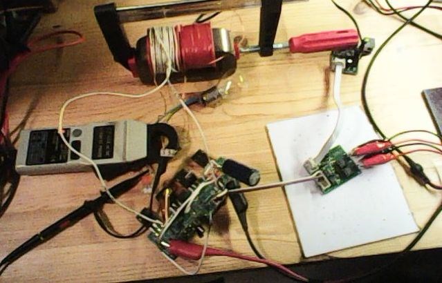
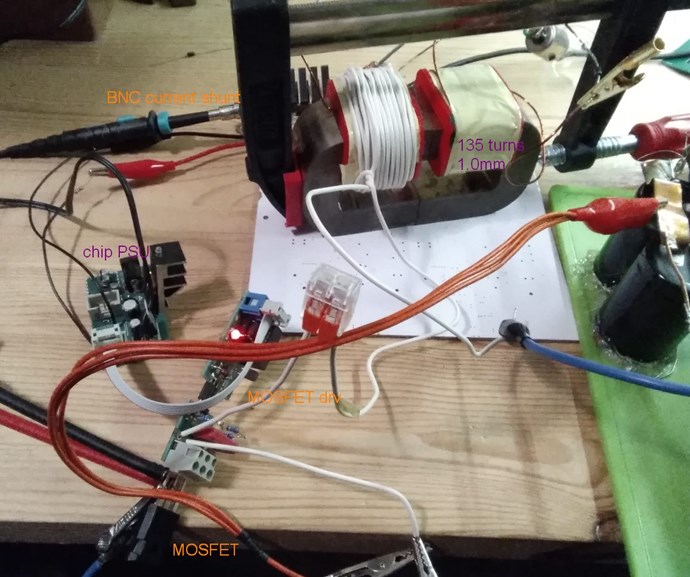
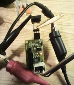
Here is a standard POC setup - in my case 14-turn primary and two POC opposing coils (0.8mm wire, ca 180 turns). Maybe @Chris will correct me if I have to modify the turns value.

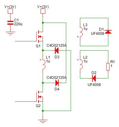
I created double-rail circuit that has special mosfet driver sync switching. Kept power supply low 3V and noticed the collapsing EMF (CEMF) to fry the mosfet. Upgraded CEMF bypass diodes to 1200V SiC shottky diodes - now better.

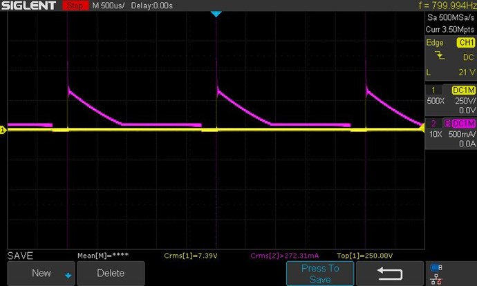
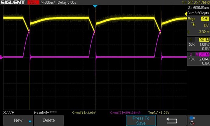
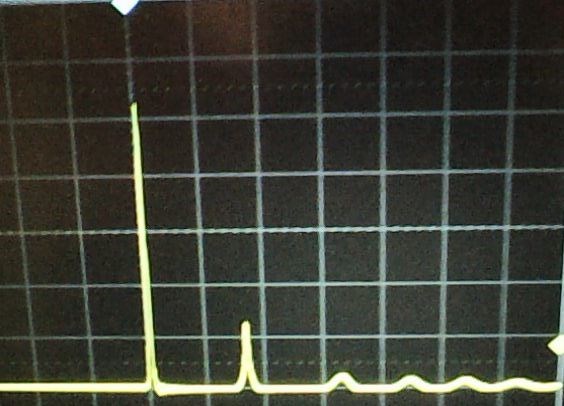
Then played with different PW and frequencies - found that the lower mosfet Q2 was a bit out of sync and still got CEMF fry at 110V level (debugged with oscilloscope).

circuit


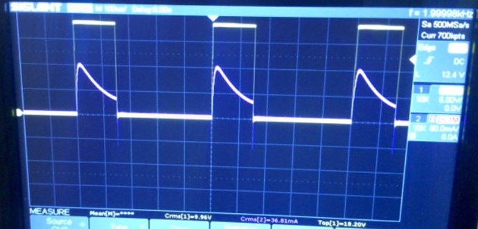
Sorry about the picture quality, noticed later in computer that it did not come out well. Using AMCC core.

Thoughts:

  • mosfets turn off very fast, mosfet driver has 10ohm resistor, primary has 14 turns, all together creates high voltage spike - mmm... I think I know where part of the problem is - my 220uF electrolytic cap is too slow to capture it
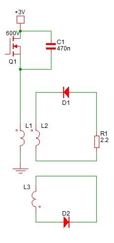
  • I really wonder how you guys manage with a single mosfet!? Either slow gate turnoff or high voltage mosfet to keep spike low.
  • oscilloscope is essential to debug mosfet driving and collector peaks

Raivo


Order By: Standard | Newest | Votes
Vidura posted this 22 November 2020

Hey Raivo, In a pulsed transformer the BEMF appears in all coils of a common core when the switch turns off, and normally if we want to trigger the POC with a magnetic pulse we should not recycle the BEMF to the source, but instead allow to be transferred to the POC and bring their voltage up. Therefore a single low side switch, without diode in the primary might be a better choice. For the protection of the switch a MOV can be used with a clamp voltage below the max rating of the MOSFET. Also check the diode polarity referenced the dot marks of the POC. Regards Vidura.

raivope posted this 07 October 2021

Hi again!

Built that setup:

Circuit - primary is pulsed from "above" with isolated mosfet driver:

Even that I had 600V mosfet, I had to protect it with parallel capacitor to trim high voltage peaks. 200MHz scope can reveal it.

L1,L2,L3 are 1:2:2 wire length, but actually I should experiment with 1:4:4 proportion.

Primary is directly on coil with a load. Diode direction is to catch the BEMF (activates on T-OFF). (that is the only direction that worked)

Secondary diode has a direction that during T-ON it is activated. (even better triangle happens when I short the diode).

PW 20% at 1200hz, current from lightbulb circuit and voltage on mosfet (goes above 248V):

PW 10% at 400hz, current from lightbulb circuit and voltage on mosfet :

Current direction from the primary (it is not 22.2 khz as scope shows):

Every scope yellow trace is a voltage (measured with isolated voltage probe) and purple trace is a current (from my new BNC current shunt).

Best regards,

Raivo

Chris posted this 22 November 2020

Hey Raivo,

Excellent Work! Thank You for Sharing!

If I may suggest, while at this stage, please keep the Mosfet Switching High Side, if you follow the thread: The Input Coil, and look for the Waveform: Here

At least while learning. Makes for easier steps forward.

The Sawtooth Waveform is important, some over look this and do not study its importance! I recommend In depth Study in this area! Do you have an Oscilloscope? Sounds like you do, check for The Sawtooth Waveform, pay special Attention here.

Great Work! Thank You for Sharing! It is great to see others Progressing!

Best Wishes,

   Chris

raivope posted this 23 November 2020

Hi,

I thought I give you guys a quick update. Took some advice and tested with a single mosfet.

Found my mini retro mosfet driver (similar circuit as quadratron) and connected it to 800V fast mosfet.

Power supply was at 3V, 12khz PW=10% where BEMF peak exceed 650V and lasted about 50ns. Mosfet runs cool, because its rating is 800V.

While zooming out - we can see 1200khz reflection

It was interesting, when I lowered frequency - at some point below 5khz this peak started to descent. I explain it so that the POC coils have its own frequency and it when it fluctuates, it creates changing impedance, and it affects the BEMF.

So - what about the current?

Did not get much current flowing yet from 3V input (tested from 100hz up, actually, the driver can run up to a few megahertz) - I had oscilloscope current clamp connected and it showed current fluctuation, but it had very short duration. In a week or two - will update component stock and will build a dedicated current shunt.

So - my advice to the beginners is to use at least 600-800V mosfet to avoid BEMF destruction.

Raivo

raivope posted this 26 November 2020

Hi,

After building my new shunt as promised, I can provide you clean picture.

The same standard POC setup:

Here I have a clean gate signal (18V, 2kHz) and current measured from lightbulb circuit (37mA).

Played from 3 to 10V - mosfet went hot, lightbulp did not start.

I know, Chris likes triangles, but still to go... (triangle must continue after the activation pulse) 

(I hate my coils so in time will build better and more symmetric coils, and later will use more expensive mosfet)

Best wishes,

Raivo


Chris posted this 07 October 2021

Hey Raivo,

Excellent work! Thanks for sharing!

All you need do now is search for Resonance, find the best Frequency and Duty Cycle, maximise the Asymmetrical Regauging Events:


Magnetic Resonance is where Currents are 180 Degrees out of Phase, Equal in Magnitude and Opposite direction.

At Magnetic Resonance, the Input will go way down, but the Output will stay the same or go up in some cases.

Great Work Raivo! You have the correct configuration, all thats need nopw is to make improvements! 

"Little Steps for little feet" - Sir Richard Feynmann

Can you see where this video plays a role here:


This, where the Magnet Drops, is the Work Region in Asymmetrical Regauging, our Input Pulse is the Regauge, where we place the Magnet on top of the Copper Tube, and at resonance, this is a very cheap process to achieve! Very little input power is needed at Resonance! For the same or better Output!

Best Wishes,

   Chris

Fighter posted this 07 October 2021

Even that I had 600V mosfet, I had to protect it with parallel capacitor to trim high voltage peaks

Be careful with those voltage peaks, they can damage your equipment.

They always appear when two opposing magnetic fields are pulsating at high frequency.

With ZPM they burned many of my IRFP250 MOSFETs.

Better go with those rated at 1200V, I use Cree/Wolfspeed C2M0160120D MOSFETs, they're fast and they handle better those spikes and they get less hot than usual MOSFETs.

Mine are 2nd generation but in the meanwhile there appeared the 3rd generation.

Regards,

Fighter

raivope posted this 23 November 2020

I want to Stress about The Sawtooth Waveform. In the Thread: Some Coils Buck and some Coils DONT, I gave the different Waveforms and how each Waveform was different depending on how we Wound, and Connected our Coils.

What waveforms, voltage or measured from shunt, did you mean current?

The second Waveform is very much more Linear that the first Waveform. - This is really important and we want to see this Linear and not the Exponential Curve. /../

same here

Figure 4. - the same.

We have read this over and over again, it is obvious for the smart mind, but my transient memory cannot handle over one thing, have to scroll back to find out what was actually meant. Chris - just a word or two are missing, can you reedit the post, and every time you write waveform expand it: a la "current waveform must be sawtooth".

Thanks for the help!

Raivo

PS! I basically understand the road. Have to find the sawtooth wave that indicates the coils are talking and generating. My coils are wound by hand and are a bit different. Will fix coils if they refuse talking. I guess then there are no limits! I see in my mind a number of different ways to pulse coils.

  • Liked by
  • Chris
  • Vidura
Chris posted this 26 November 2020

Hello Jcil.nl,

I agree! Stop Posting Jcil.nl! Until you have something of VALUE To Share!

Your posts are really just spam and non-sense! I will Ban and Delete your Posts if you continue!

You have been put on Moderation until further notice!

Best Wishes,

   Chris

  • Liked by
  • Jagau
  • Shadow_
Chris posted this 23 November 2020

Hey Raivo,

Voltage and Current will follow each other, so both the Voltage and the Current Waveform will have a Sawtooth Waveform! You will see when doing further experiments.

Experiment is the path forward, this will give you more insight! Follow what I shared in my video and remember, this is just the start!

Best Wishes,

   Chris


P.S: I have moved the post to the thread: The Sawtooth Waveform.

  • Liked by
  • raivope
We're Light Years Ahead!
Members Online:

No one online at the moment


What is a Scalar:

In physics, scalars are physical quantities that are unaffected by changes to a vector space basis. Scalars are often accompanied by units of measurement, as in "10 cm". Examples of scalar quantities are mass, distance, charge, volume, time, speed, and the magnitude of physical vectors in general.

You need to forget the Non-Sense that some spout with out knowing the actual Definition of the word Scalar! Some people talk absolute Bull Sh*t!

The pressure P in the formula P = pgh, pgh is a scalar that tells you the amount of this squashing force per unit area in a fluid.

A Scalar, having both direction and magnitude, can be anything! The Magnetic Field, a Charge moving, yet some Numb Nuts think it means Magic Science!

Message from God:

Hello my children. This is Yahweh, the one true Lord. You have found creation's secret. Now share it peacefully with the world.

Ref: Message from God written inside the Human Genome

God be in my head, and in my thinking.

God be in my eyes, and in my looking.

God be in my mouth, and in my speaking.

Oh, God be in my heart, and in my understanding.

Your Support:

More than anything else, your contributions to this forum are most important! We are trying to actively get all visitors involved, but we do only have a few main contributors, which are very much appreciated! If you would like to see more pages with more detailed experiments and answers, perhaps a contribution of another type maybe possible:

PayPal De-Platformed me!

They REFUSE to tell me why!

We now use Wise!

Donate
Use E-Mail: Chris at aboveunity.com

The content I am sharing is not only unique, but is changing the world as we know it! Please Support Us!

Thank You So Much!

Weeks High Earners:
The great Nikola Tesla:

Ere many generations pass, our machinery will be driven by a power obtainable at any point of the universe. This idea is not novel. Men have been led to it long ago by instinct or reason. It has been expressed in many ways, and in many places, in the history of old and new. We find it in the delightful myth of Antheus, who drives power from the earth; we find it among the subtle speculations of one of your splendid mathematicians, and in many hints and statements of thinkers of the present time. Throughout space there is energy. Is this energy static or kinetic? If static, our hopes are in vain; if kinetic - and this we know it is for certain - then it is a mere question of time when men will succeed in attaching their machinery to the very wheelwork of nature.

Experiments With Alternate Currents Of High Potential And High Frequency (February 1892).

Close