

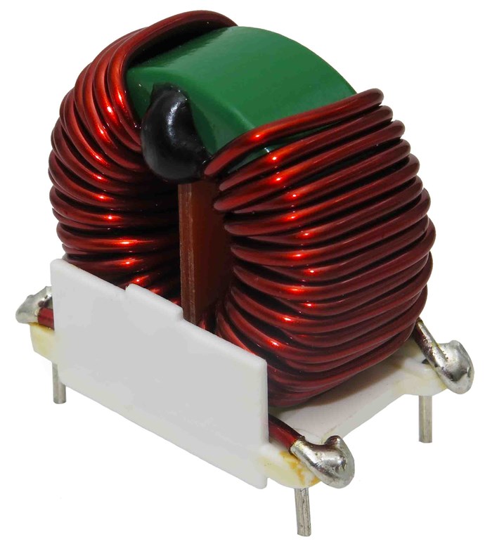
Bucking Coils are used in many ways. One example is “Common Mode Chokes”, an example that has perhaps clouded the entire concept of Electromagnetic Induction. Let’s look at the “Common Mode Choke”
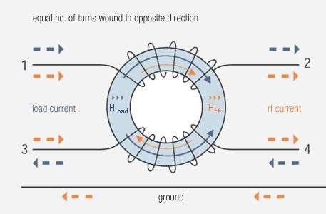
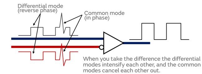
A common mode choke is where both line and neutral windings are wound on a single core. When using a current compensated choke to decrease common mode noise, (the interference pattern or the unwanted noise) you want to have a high impedance at the unwanted frequencies to knock down that unwanted noise.
Let’s think, what’s is the actual purpose in Common Mode Chokes? What are they designed to do? What are they particularly good at doing? Think really hard at what they are doing. Because it is really important to understand!
Any Coil carrying a Current will always have a Magnetic Field. The Magnetic Field is defined, by Amperes Law, as: B=μ0nI
Where:
· B = Magnetic Field in Gauss (CGS) or Tesla (MKS)
· μ0 = The Permeability of Free Space, or Permeability of the Core Material μr
· n = is the number of turns per unit length.
· l = The length.
ref: see Magnetic Fields Produced by Currents: Ampere’s Law
You can see, the term Ampere Turns: AT = NI, which is Turns (N) x Amperes (I). This means the more Current through the more Turns we have, the more Ampere Turns we have, this is part of the above equation, thus, the more Magnetic Field we have!
Kirchhoff’s Current Law states that the Current In to a Node, must be the same as the Current Out of the Node, and so we have the same Magnetic Field in each Coil in our Common Mode Choke! Each Field is Equal and Opposite.
There is a problem with the way we understand Magnetic Induction, that may already be apparent. We see the exact same requirements that are necessary in Electromagnetic Induction, but yet we see none, we see the opposite! We see the reduction of Transients, surges, and the like. Thus the design and use of the Common Mode Choke.
But why?
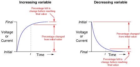
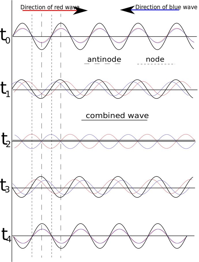
The answer is surprisingly simple! Because the Magnetic Fields are being held steady, they are not allowed to change, the Current is Equal and Opposite, it is a locked, a Rigid System
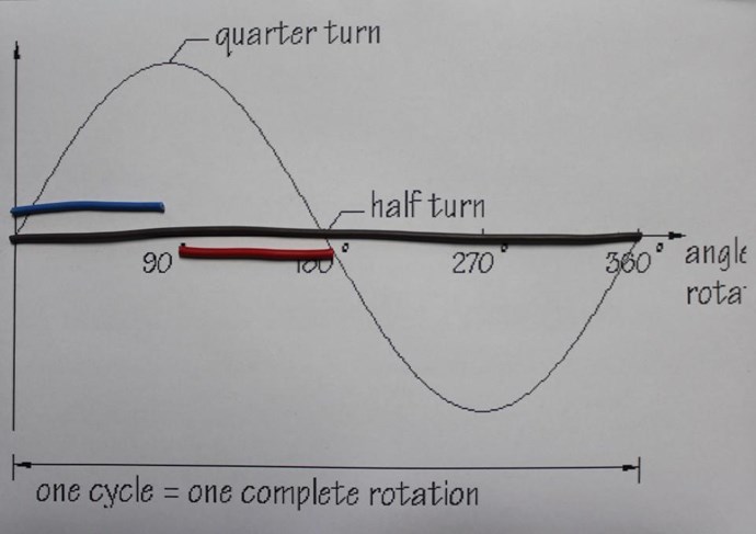
This is NOT what happens in an Electrical Generator! The Magnetic Field is aloud to Change over Time in respect to the timing of the System. This is not the case in the Common Mode Choke! The Magnetic Fields in an Electrical Generator dynamically change, at any one point in time and the “Generating” Coil can vary with Load, so the total System is dynamic, changing, not held steady.
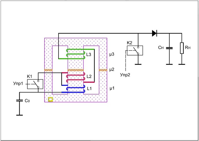
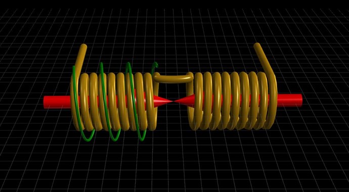
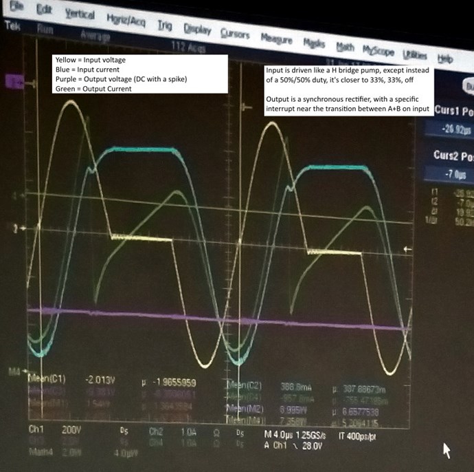
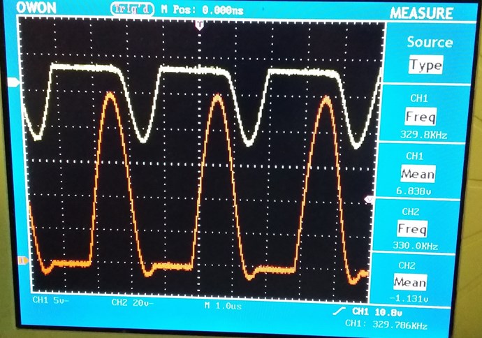
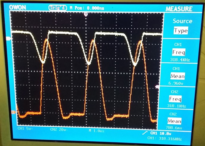
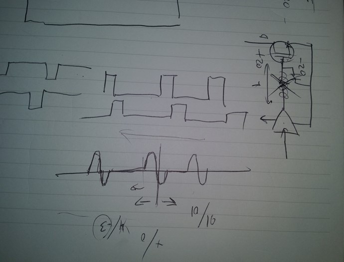
So, delay one of the Coils Magnetic Field relative to the other in the Common Mode Choke and see what happens… Wow we have a completely different System! No longer any good as a Common Mode Choke, not serving the purpose of a Common Mode Choke anymore.
Bucking Coils, or I like the term Partnered Output Coils, can and do "Generate" Electrical Energy! You need to let the System Breath, bring it to life!
Chris


---open-tesla-research.jpg?width=20&crop=0,0,20,20)


