

Hi guys! This tread is a place to share my experience with the POC. It will be as simple as I am. So do not ask for measurement, it all about the phenoment. Hope you will appreciate and participate! 😁
Wistiti experiments :)
- 8K Views
- Last Post 04 January 2023

Wistiti
posted this
23 December 2018
- Last edited 23 December 2018
Here are one of my first experiences with the POC.
- Liked by
-

-

-

-
- and 5 others


Chris
posted this
23 December 2018
Hey Wistiti,
Excellent thread!
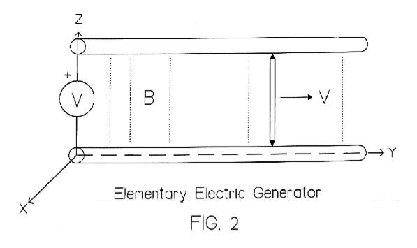
My first Experience with POC was experiments prior to Jul 18, 2011, published in this video:
These experiments included observing the necessity for Current Flow:
Floyd Sweet making the same observation:
If the voltmeter draws no current, there can be no electromagnetic force on the free electrons of the wire. Therefore, the E.M.F along the path of the metal conductors including the moving conductor is zero.
Its worth noting, the Positive Energy passage talks about Clockwise and Counter Clockwise E.M.F's. Directly after this passage, Floyd Sweet talks about: INDUCED MOTIONAL FIELD - NEGATIVE ENERGY, unfortunately there is not much useful information in there.
Any and all Insulated Copper Conductors when carrying a Current have an associated Magnetic Field. Voltage can be present with NO Current! Current is a function of the Load and the Source.
Chris
- Liked by
-
-

-
-

- and 3 others
Wistiti
posted this
23 December 2018
- Last edited 23 December 2018
Completely agree Chris!!! And I will add when using DC for the source, the current from the output POC must be extracted to buck the primary DC source... Like I do is this video. (Sorry for my English) 😉
- Liked by
-
-
-

-

- and 8 others

Chris
posted this
23 December 2018
- Last edited 23 December 2018
Wistiti, one of my favorite videos of yours!
I started with a few small, for most perhaps insignificant, effects. Just a few coils, having a bit of insight, looking for something. Knowing in my heart that there was something to find there. Took me some years to make real progress, much confusion and mistakes along the way.
You my friend are a natural! Also, your English is perfectly understandable!
Chris
- Liked by
-
-
-
-

- and 2 others

Jagau
posted this
24 December 2018
Hi wistiti
Very interesting this video. I take note of it.
You know in this forum we learn things that move us forward. Thanks for sharing.
Jagau
- Liked by
-
-
-

-

- and 2 others
Wistiti
posted this
24 December 2018
- Last edited 24 December 2018
Yes my freind!
And this is (openly sharing) what we move us forward!  Thanks to Chris to bring it back to us!!!
Now it's up to us (as a team) to improve it!
😀
- Liked by
-
-
-
-
- and 1 others
Wistiti
posted this
27 December 2018
- Last edited 27 December 2018
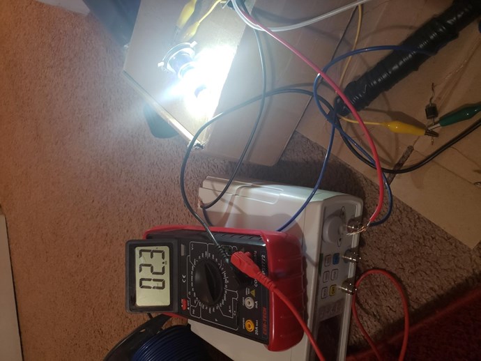
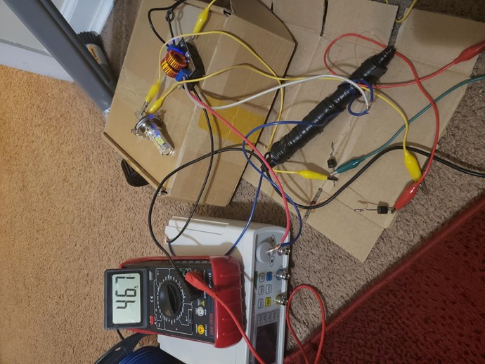
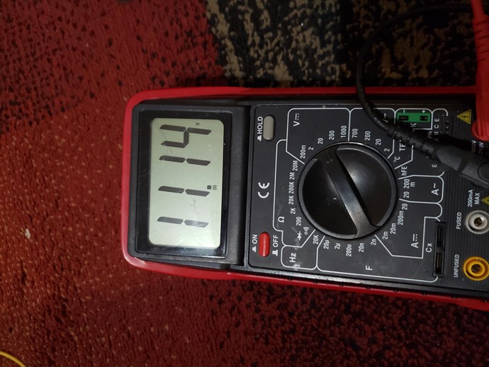
Hi guys! Just let you know I have passed the last day's playing with POC.
I build a toroid transformer (really long to wind on a toroid...😒) on a plastic ring (so air core) . The effect is there but way less than when using a magnetic core. The couplings seem not optimal... I will continue my experiment with magnetic core. 😀
- Liked by
-
-

-
-
- and 3 others

Zanzal
posted this
27 December 2018
That toroid looks awesome. If you have only been playing with it a day then its too soon to give up IMO, but you need a signal generator to get the most out of it. PM me if you want to sell it.
- Liked by
-
-
-
-
- and 2 others
Wistiti
posted this
27 December 2018
Thank you Zanzal ! I have not yet give up on it. It took me so much time to wind it I will keep it for further test. 😉 I don't have a signal generator. But agree, it might have a sweet frequency spot. Have you a good one not to expensive to suggest?
- Liked by
-
-
-
-
- and 2 others
Zanzal
posted this
27 December 2018
Yes, I don't blame you, it is a work of art, personally I'd mount it on my wall before I sold it had I built something so nice.
Regarding function generators your best pick for a starter is the JDS6600 15Mhz for $65. For a more complete answer I posted more options in the Function Generators thread.
- Liked by
-
-
-
-
- and 2 others

Vidura
posted this
28 December 2018
Nice coil Wistiti! Agreed that a function generator will be useful, resuming the latest information we have to look for magnetic resonance, and the frequency depending on the corematerial, so we can assume that for an aircore much higher frequencies will be required, like in the aircore devices from Don Smith. Also a disruptive discharge on the primary could likely set up a resonance. Wish you success , Vidura.
- Liked by
-
-
-
-
- and 2 others
Wistiti
posted this
28 December 2018
Thank you Vidura . Disruptive discharge is the way I explore now to improve the effect.
It seem to be a must... I'm looking for a way to do it at low voltage. I try with a reed switch at the base of a transistor and have interesting results but I'm wondering what are the other ways I can make this kind of abrupt discharge without hv and spark gap...??🤔
Any idea are welcome!
- Liked by
-
-
-
-
- and 3 others
Vidura
posted this
28 December 2018
As a suggestion i had good results with a mosfet and capacitor array, one device you can see in many of my vídeos, it has five mosfets in parallel and a capacitor bank on the supply rail and with very short dutycycle it give good pulses for striking the resonance. Also a SCR with a neon as trigger works very well at a little higher voltages. Sorry that I cant load up image's until fixing the internet installations, my phone dont have enough memory to do it. In a few days it should be up again ,then I can share some circuits I have used.
- Liked by
-
-
-
-
- and 2 others
Zanzal
posted this
29 December 2018
- Last edited 29 December 2018
Any idea are welcome!
You could try using an avalanche pulse generator. Basically you need a HV source, through a resistor you charge a HV low pf capacitor, the capacitor gets discharged when it reaches the avalanche voltage of the transistor. You can adjust the frequency of the pulses by changing the resistance, but you want to keep enough resistance so that the capacitor cannot recharge too quickly after discharging.
You set the voltage by using a number of cheap transistors with a known avalanche voltage in series. So if you use an npn with an avalanche voltage of 200V and you want 600V pulses you just use 3 of them in series. Keep the capacitance low to avoid damaging them. So at 100pF it might be ok, but 600V at 100nF you might have dead transistors.. Or that's how I understand it anyway (never built one myself).
You can see an example of the most basic one like I described here: Avalanche Pulse Generator Circuit
- Liked by
-
-
-
-
- and 3 others
Wistiti
posted this
29 December 2018
Thank you guys for the info! Vidura I will wait to see your picture. Have a good day!
- Liked by
-
-
-
-
Wistiti
posted this
27 July 2019
Hi freinds!
I have a spare time to experiment and i want to share my findings with you.
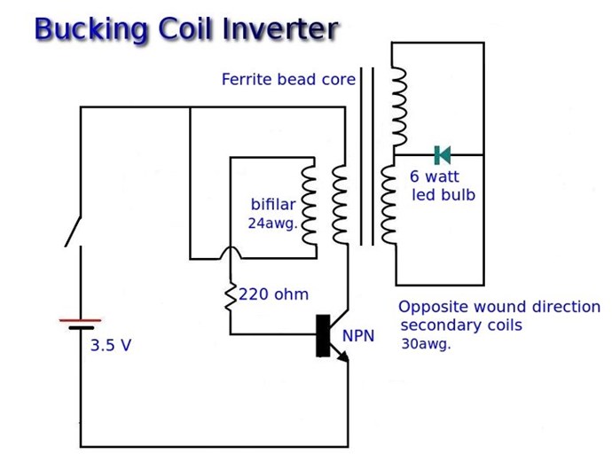
I have rebuild the Skywatcher bucking coil inverter and have good results.
Since now, im charging my 3rd 12v 7,2ah battery with a 5v 5.3ah usb power bank.
The usb power bank have drop of 0.03v and im toped 3 12v 7,2ah batt to 15v!!
The new thing i have done is give a space between the POC on my ferite rod. The primary is still a joule thief. The output diode have to be oriented the good way to assist the primary.
My little bit to share.
Keep on experimenting!!!!
- Liked by
-
-
-
-
- and 5 others
Chris
posted this
27 July 2019
Hey my friend,
Very nice! Excellent work! Power coming out at both ends!
Chris
- Liked by
-
-
-
-

Satmedia
posted this
29 July 2019
Thank you for your report of the interessting results.
Do you have a schematic of the skywatcher poc circuit / coil windings?
Regards Roland
- Liked by
-
-
-
-
- and 1 others
Wistiti
posted this
30 July 2019
- Last edited 30 July 2019
Thank you for your report of the interessting results.
Do you have a schematic of the skywatcher poc circuit / coil windings?
Regards Roland
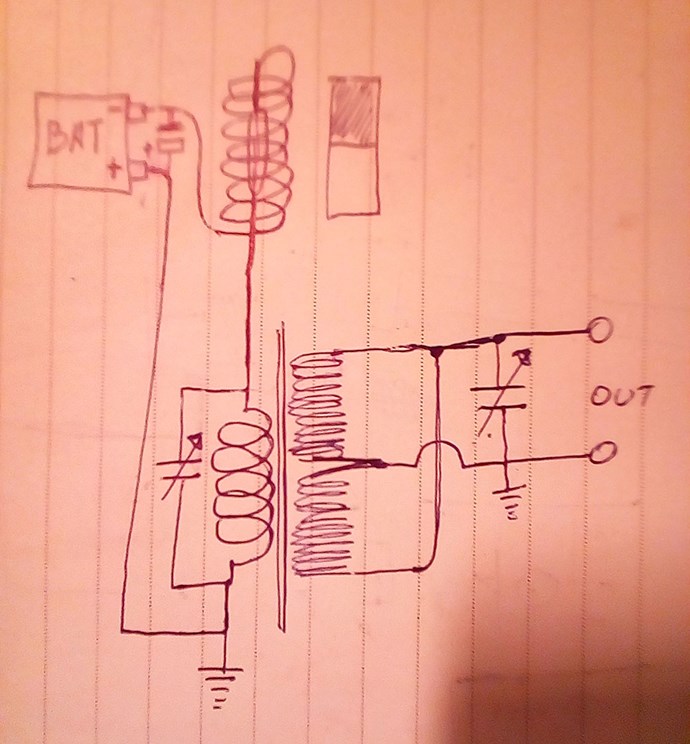
Sure! Here it is. Make sure to have a space between the POC. Reverse the diode to have the best output snd see a reduced consumption of the primary's when the secondary is loaded.
- Liked by
-
-
-

-
- and 4 others

leonel
posted this
28 January 2020
Thank you very much Wistiti for sharing such valuable information. I'm pulling it and I made the buck coil of 500 turns each, I don't know how many turns, can you help me with that please?
- Liked by
-
-
-
-
- and 3 others
Wistiti
posted this
28 January 2020
Thank you very much Wistiti for sharing such valuable information. I'm pulling it and I made the buck coil of 500 turns each, I don't know how many turns, can you help me with that please?
Hi Leonel. I have not try with as much as 500 turns.
Mine are something between 200 and 350 turns.
The primary use less turns 30 to 100... you have to experiment and look for the effect.
Will be nice to read your results!
- Liked by
-
-
-
-
- and 4 others

leonel
posted this
29 January 2020
Thank you very much Wistiti,
ok, as I told you, it was about 500 cw and ccw turns, then I put the primary with 120 turns in two-wire (60 +60). I tried several ways, with 2n3055 transistor and buck booster card; The result was inverse all the time (not good).
At the moment I measured the current in input and it was lowered with load but the voltage at the output also dropped a lot.
I don't know where I'm wrong, maybe I must buy material and do it all over again. some suggestion??
- Liked by
-
-
-
-
- and 3 others
Wistiti
posted this
29 January 2020
- Last edited 29 January 2020
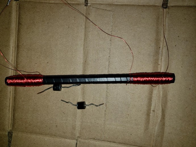
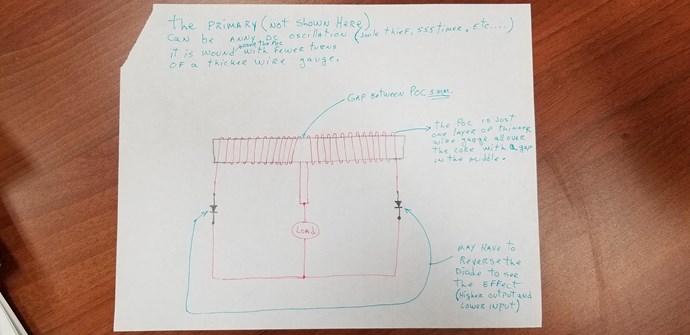
Hi Leonel. Your poc in my opinion are to far from each other... Here a picture of how i wind mine in this experiment.

Hope its helped!
- Liked by
-
-
-
-
- and 4 others
leonel
posted this
29 January 2020
Thanks you, Yes you are right, wasn't sure how far it should go between them. Ok here we go again (never give up!)😁 I just need a little more time. Thanks
- Liked by
-
-
-
-
- and 1 others
Chris
posted this
29 January 2020
- Last edited 29 January 2020
Hi Lionel,
Wistiti is very knowledgeable when it comes to Partnered Output Coils! CD Sharp is also another, there are others here also very skilled!
Everyone will tell you the same, its practice, doing the experiments, learning from them, learn as much as you can from each experiment!
From my work, 500 Turns is way to many.
40 to 200 turns is about the figure you want to be!
This forum and the fantastic people here have a HUGE amount of information, if you want to learn, then you in the right place! Its good to see your work and your progress! Keep up the good work!
P.S: PayPal Donate Button may help you in your progress if you wish to look at this? there are rules to this, so please read and understand the rules.
Best wishes
Chris
- Liked by
-
-
-
-
- and 4 others
leonel
posted this
29 January 2020
- Last edited 30 January 2020
Thank you Chris.
That's why I've switched from ou.com to here, because I know I'm in the right place, with right guys. Thank especially to you! 
- Liked by
-
-
-
-
- and 5 others
leonel
posted this
13 February 2020
My brother Thanks a lot, I got it I need to improve that, but so far I could charged a battery, a little slow, but it go up.
I also charge a 15,000 uf very fast capacitor, I have video and photos but it has been a bit difficult to upload, maybe I'll put more later ... Everything with 2.5 v two batteries an it lost 0.01v
OK I think it's time to go for something bigger

- Liked by
-
-
-
-
- and 1 others
leonel
posted this
13 February 2020
- Last edited 13 February 2020
https://youtu.b
I'll switch for other account
- Liked by
-
-
-
-
Wistiti
posted this
13 February 2020
Great achievement Leonel! Im happy you see the effect. 👍
- Liked by
-
-
-
leonel
posted this
13 February 2020
Thank you very much everyone especially Chris and wistiti. cd I'll put it back but I need to make an account for those!
- Liked by
-

-
-
-
Vidura
posted this
13 February 2020
Very good to see other replication of Wistitis experiment. Someone has noted that the magnetic fields are aligned, not opposed regarding the schematic. Interesting. Vidura.
- Liked by
-
-
-
-
- and 1 others
leonel
posted this
13 February 2020
Thanks Vidura, I don't understand, you mean NN in the center and SS in the corner?
- Liked by
-
-
-
-
- and 1 others
Chris
posted this
14 February 2020
Very good to see other replication of Wistitis experiment. Someone has noted that the magnetic fields are aligned, not opposed regarding the schematic. Interesting. Vidura.
Hey Vidura, if I may, where did you see this, the aligned Fields?
@Loinel, Vidura means North North, Opposing Magnetic Fields as compared to North South, meaning Aligning the Magnetic Fields. I did not see any mention of this, only diode directions, but Wistiti did say adjust the diodes to make this work.
Best Wishes,
Chris
- Liked by
-
-
-
-
- and 1 others
Vidura
posted this
14 February 2020
Hey Chris , all following.
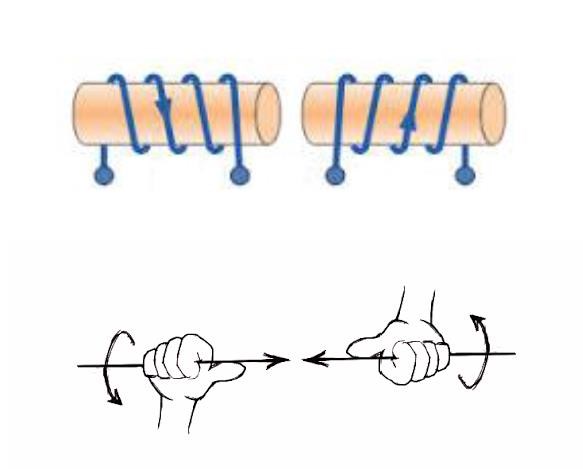
in the sketch here you can check with the right hand grip rule that the diodes force the current to align the fields NS-NS.
also in the earlier posted schematic here as the coils are wound CW-CCW the fields align in contrast to the Don smith POC where the coils are wound in the same sense , and thus fields opposes. But this does not mean that there are no opposing fields at all, as also the input coils have to been taken in account.
Regards Vidura.
- Liked by
-
-
-
-
- and 1 others
Chris
posted this
14 February 2020
- Last edited 14 February 2020
Hey Vidura,
Ah, yes, I thought that's where you may have come to this conclusion.
@Wistiti and @Lionel - Please can you show what your Circuits are, using the Diodes and the Right Hand Grip Rule to verify the Field Direction vs the Diode Polarity.
If you can measure the Current, if you have a scope, to show what the Current is doing, I would be grateful!
Remember we have had occasions where the Current flows against the Diodes so a Diode is not the best way to determine the Magnetic Field directions!
Best wishes,
Chris
- Liked by
-
-
-
-
Wistiti
posted this
14 February 2020
- Last edited 14 February 2020
Very good to see other replication of Wistitis experiment. Someone has noted that the magnetic fields are aligned, not opposed regarding the schematic. Interesting. Vidura.
Hi Vidura. Sorry but im not agreeing with you on this... The way i see it the magnetic field is forced to buck cause of the way the diode are positioned. The current flow through the diode . 😉
- Liked by
-
-
-
-
- and 1 others
Wistiti
posted this
14 February 2020
Hey guy's Sorry but i can not give some scope shoot cause i have no scope....
The schematic is the same Skywatcher "original " give ghe first time with few modification. I will try to draw it tomorrow.
The way i see it the poc field opposes.
Please, remember what i have said in my first post, this tread is there to show my experiment. Not to debate on mesurement or theorise over a certain point...
Maybe it's a better idea to start a new tread to talk about this.
Thank you. 🌞
- Liked by
-
-
-
-
- and 2 others
Chris
posted this
14 February 2020
- Last edited 14 February 2020
Thank You Wistiti!
Yes, from your video here, this is what I also saw:
I agree, if we need to further investigate the Diode to Coil Polarity, I think we need to create a new thread and not take this thread off topic. To those doing the experiments, please change the Diode Polarity untill you see the above effects! Its important you get the best from your Machine, and this is what Wistiti has been showing for years now!
Thank You Wistiti! Sorry to distract you my friend I know you were busy.
Best Wishes,
Chris
- Liked by
-
-
-
-
- and 1 others
Wistiti
posted this
14 February 2020
No problem freinds! I will be a pleasure to give my opinion in another tread. 😉
- Liked by
-
-
-
-
- and 1 others
Wistiti
posted this
23 March 2020
- Last edited 23 March 2020
Hi guy's! I have try many ways to drive the POC this last time. One thing i am sure is the polarity is important... Hope it help!
- Liked by
-
-
-
-
- and 4 others

stand by
posted this
23 March 2020
hello Wistiti
Do you use the same strategy as in the previous videos?
Which transistor do you use? Thanks for sharing
respectfully cristian albax
- Liked by
-
-
-
-
- and 2 others
Wistiti
posted this
23 March 2020
Hi Stand by. Yes its the same strategy.
The transistor is c3552 npn.
Hope it help!
- Liked by
-
-
-
-
- and 1 others
Wistiti
posted this
24 December 2020
Hi Drago. I suggest to change the core for a better one... if you really have nothing to salvage from (ferrite or laminate steel) i mean real magnetic transformer, I suggest you to use air core instead of what you are currently doing...
- Liked by
-
-
-
-
- and 2 others
Wistiti
posted this
25 December 2020
Hi Drago. Interesting to see you use single coil with a signal generator and a scope. With all this equipment, i suggests you to build the circuit Chris have shared. It is much more like the one you have then mine and many here have experienced with it. I use a bifilar coil (as a joule thief) for my primary.
I'm happy to se you are a builder I believe it's the way to go for learning. I suggest you to start your own thread. This way everyone can evolve with their own experience.
Thanks for sharing your work.
- Liked by
-
-
-
-
- and 3 others
Chris
posted this
25 December 2020
- Last edited 25 December 2020
Hi Drago,
Wistiti has very kindly given us a very detailed set of experiments here. With anything in life, it is important to follow as closely as possible, the guideline possible! Attention to Detail is very important! on this thread, you will find the Circuit used and also the Video shows the Coir, Coils and approximate wire size.
I kindly ask, please Pay Special Attention to Detail, please ensure you copy to the best of your ability, the experiment.
When one changes things, one is no longer replicating this work, they are off, working on something unrelated. Wistiti has made great advances, if you want to learn what he is trying to share, you need to follow the guidelines.
Like Wistiti said, it is good to see experiment, but I do ask, please stay on target if you want to learn!
Best Wishes,
Chris
- Liked by
-
-
-
-
- and 2 others
Wistiti
posted this
27 December 2020
Currently playing around the last circuit of L0stf0x.
Nothing special to report for now...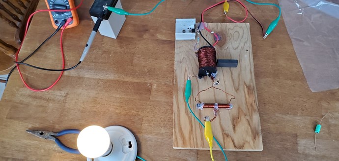
Will have some time in the holiday to experiment 🙂
- Liked by
-
-
-
-
- and 3 others

L0stf0x
posted this
28 December 2020
- Last edited 28 December 2020
My dear friend, If you searching for the growing effect I think is better to follow my circuit and not use transistor. But this is just an opinion. I have no idea how this effect works.
But if you just testing for overunity as a complete circuit, I tell you is not complete..
Is my fault I wasn't clear that this is just a testing circuit... At my past messages I forgot to explain what I was trying to accomplish..
Usually I try different setups that jump in my head but without any plan. Just to test and observe things. But this had a plan.
let me explain.
I wanted to make the simplest setup that may be proved overunity.. So I started from the primary side trying to spend the lowest power to make oscillations.
You know from past experiments that this classic reed setup is very efficient! It offers free bidirectional switching, with the cost of the difficulty to get a stable frequency and the current limits. That is working but the battery needs to be low capacity so you will not worry about excessive current passing through reed. Also a high inductance coil does act as current limiter, but to be sure do both. Of course effect proved me wrong and fried the reed. That made me stop and try to replicate the effect... So is my fault I should explain before I let you proceed with that circuit.
The main purpose is to get secondary and third in resonance but in a way that will not kill reeds oscillations... To be isolated somehow. This will transfer power to third coil and make secondary coil a big resistor, this resistor must not kill reed's oscillations somehow. So I am not sure I have this correct in my head.. It was in plan for testing it.
So again the circuit I showed at my thread is just a test, is not complete.! I am sorry my friend for my fault.. but because of what happen (growing effect), it was the reason I stopped and post it.
The secondary is bifilar... BUT It shouldn't .. remember I was testing... I had it ready so I give it a go..
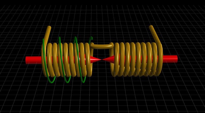
The plan was the secondary to be electrically connected but be inductively separated coil away from primary, to protect reed's oscillations and be on a core with a third coil. (See image) So by having secondary and third coil in resonance with the reed working is most important. Power will be transferred to third coil and also because secondary is electrically connected to primary (remember primary is only needed for the reed to work.. It is not a real primary), will appear as a large resistor (extra current limiter) at primary.
Now the secondary and third coil should be tanked with a capacitor each, to be in resonance, the third coil in my opinion has to be POC.. like don smith secondary for best results. But even with a simple coil should work fine.
This is the circuit I had in mind.. So I will continue working on it..
Resonance is a must for the cored coils. The hard is to have reed also tuned.
The electrolytic capacitor at battery may be a problem, I just put it there for testing.
This is a basic concept circuit.
- Liked by
-
-
-
-
- and 2 others
L0stf0x
posted this
28 December 2020
I know it is difficult to get more than 2Khz from reed but maybe a passive frequency multiplier can be between the primary and secondary coiling to bring frequency more compatible with the tank LC's. I am not sure it will fit but I guess it will not kill reed oscillations as long as the high frequency is a complete wave division. Just thinking.. needs testing!
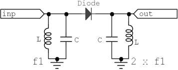
https://doc.xdevs.com/docs/_Materials/Frequency_multiplier_circuits_survey_and_theory_ROSU.pdf
- Liked by
-
-
-
-
- and 2 others
Wistiti
posted this
28 December 2020
Hey L0stf0x my freind, please don't be sorry!!
I have give a try to your original circuit (no transistor and a toroidal core) but my reedswitch are bigger.
Anyway it give me some idea to try when I see your experiment and I have good time experimenting around it! So please don't be sorry!😉
Thank you for explaining your global idea, I found it very interesting! It is nice to see your head is still boiling with brilliant ideas!😁
I will continue to share my experiences here.
Have a great day my freind!
- Liked by
-
-
-
-
- and 2 others

deleted
posted this
28 December 2020
- Last edited 28 December 2020
[img]https://www.aboveunity.com/content/uploads/b5d8d256-5657-4ec2-ac7c-a741014a20b4/e8ba81c8-a939-4ed9-8aa2-ab51014bd4fa_wistiti's-poc-experiment.jpg?width=690&upscale=false[/img]
The load should be on one coil only, the other must have least resistance for max Lenz to the coupled coil.
- Liked by
-
-
-
-
- and 1 others
Chris
posted this
28 December 2020
Hi Alann
No, this is not correct! Wistiti is showing the Partnered Output Coils here! Equal load must be on each Coil at the same time to make this work!
Magnetic Asymmetry is how Lenz's Law can be avoided on the Input Coil, not shown in this image you show.
Experiment is the best path forward, we will help you if you want to gain a better understanding, please create your own thread.
Best Wishes,
Chris
- Liked by
-
-
-
-
deleted
posted this
28 December 2020
- Last edited 28 December 2020
Hi Chris,
The image I copied from this thread is correct then? I think this is the first one I see that resembles the 3d render with the U connection between the coils.
Then I did understand it incorrectly that one coil must have least resistance to maximally oppose the changing flux.
- Liked by
-
-
-
Wistiti
posted this
28 December 2020
Hi Alann. You are right about what you say. It is one of the way. Im showing another's one like Chris said. There are different configuration where poc can be used.
Ciao!
- Liked by
-
-
-
Chris
posted this
28 December 2020
Hi Alann
Yes, Wistiti has shared everything as he has laid out, this post:
Hi Drago,
Wistiti has very kindly given us a very detailed set of experiments here. With anything in life, it is important to follow as closely as possible, the guideline possible! Attention to Detail is very important! on this thread, you will find the Circuit used and also the Video shows the Coir, Coils and approximate wire size.
I kindly ask, please Pay Special Attention to Detail, please ensure you copy to the best of your ability, the experiment.
When one changes things, one is no longer replicating this work, they are off, working on something unrelated. Wistiti has made great advances, if you want to learn what he is trying to share, you need to follow the guidelines.
Like Wistiti said, it is good to see experiment, but I do ask, please stay on target if you want to learn!
Best Wishes,
Chris
Explains what Wistiti has done and shared. Its all correct, if one follows the outline
Best Wishes,
Chris
- Liked by
-
-
-
-
- and 2 others

OriginalSkywatcher
posted this
08 January 2021
Hi all, Hi wistiti, back to making some experiments, was taking a little break, to gain some perspective on things.
I'm using a 555 timer to pulse a single 600 volt n-channel mosfet.
Using a ferrite c-core, from older TV flyback.
I super glued the two halves of the core together, so no gap.
Using 24awg. for POC coils, one coil on each side, on the longer length sides, one side is cylinder shape and other is square shape, resistance per coil is around .7 ohms.
On the cylinder shaped side, an 18awg. primary coil is wound on top of the POC coil, in same winding direction as POC coil underneath.
Using the 555 timer, the pulse on time is adjustable and the off time, as well as frequency, by changing a capacitor.
I have come upon a setting, that is not showing any input wattage, on my killiwatt meter, while powering a homemade 12 volt led bulb.
It is lighting to a usable, night light type level and yet the meter doesn't even show at least .1 watts, which is the bare minimum it starts showing readings at, yet it shows zero.
I'm using a 19 volt dc laptop power supply as input to primary coil/mosfet and that power supply is plugged into the killiwatt meter.
Also using a 12 volt dc power supply, for powering the 555 timer.
The POC coil underneath the 18awg. primary coil, has an ultra fast diode, going to the homemade, 12 volt led bulb.
The diode is wired to conduct, when the mosfet is off, which means the positive of the diode, is connected to the drain of the mosfet.
The other POC coil, on the opposite side of the ferrite core, is short circuited upon itself, if this is not done, the led output is reduced to less than half the brightness or more.
Will continue to experiment over the winter here.
peace love light
- Liked by
-
-
-
-
- and 2 others
leonel
posted this
08 January 2021
- Liked by
-
-
-
-
- and 1 others
Wistiti
posted this
08 January 2021
Hi Sky! Nice to have you back! I have learn from you since the beginning of this journey!😊
What you said about your experience seems really interesting! Can you share a schematic of it please? It will be much easy for me to understand with an image. 😉
It will also be a pleasure to replicate it.
Thanks for your return am happy to see you back!
- Liked by
-
-
-
-
- and 1 others
OriginalSkywatcher
posted this
09 January 2021
Hi leonel, I will start work on that tonight.
Hi wistiti, Thanks for your kind words, good to be back experimenting, though I've been keeping an eye on posts in this forum, will start working on the schematic.
peace love light
- Liked by
-
-
-
-
- and 1 others
OriginalSkywatcher
posted this
09 January 2021
Hi all, here is the schematic of the partnered output coil generator.
peace love light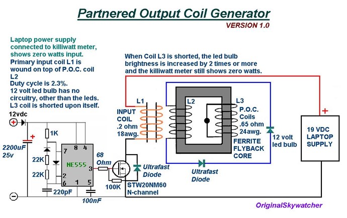
- Liked by
-
-
-
-
- and 4 others
Wistiti
posted this
09 January 2021
Thanks you sky! I think you should share this in your own thread. It's your invention and you deserve to be recognized for that. 🙂
Thanks again for sharing your experience with us!! 🌞
- Liked by
-
-
-
-
- and 1 others
OriginalSkywatcher
posted this
10 January 2021
Hi wistiti, not my invention, just me experimenting with ideas Chris has shared.
I think i will start a thread, since I have some theories on how this is working and showing zero watts on the killiwatt meter.
Of course, it falls inline with what chris has shared, as he has obviously done many more experiments and shared his ideas as well.
peace love light
- Liked by
-
-
-
-
- and 3 others
leonel
posted this
12 January 2021
Thank you very much OriginalSkywatcher for sharing this schematic with us! I will be waiting when your thread starts, I would like to know more details, so that I can replicate.
- Liked by
-
-
-
-
- and 1 others
Wistiti
posted this
12 January 2021
Hi Leonel Sky have already started a new thread.
You should give it a look! 😉
- Liked by
-
-
-
-
- and 1 others
Wistiti
posted this
12 January 2021
- Last edited 12 January 2021
Hello everyone! I have finished to build the transformer like the one OS (OriginalSkywatcher) have share. It is an experiment i want to try since a while but have not and when I see him, it give me the will to go!😁 On my setup, the POC are 222 turns each (23 awg) and the primary is 55 turns (18 awg).
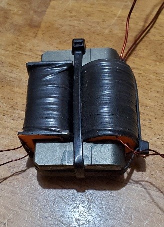
I have really few spare time for now but when time permits the next step will be the 555 timer control circuit. I plan to use the one shared by Jagau. Happy building to everyone! 🌞
- Liked by
-
-
-
-
- and 3 others
OriginalSkywatcher
posted this
13 January 2021
Hi all, Hi wistiti, nice work, coil bobbins look nice also, yes, 3d printers are very useful.
Not sure I've seen the 555 timer circuit shared by Jagau, could you share that, thanks.
peace love light
- Liked by
-
-
-
-
- and 1 others
Wistiti
posted this
13 January 2021
Hi Sky!
Here is the tread from Jaugau.
https://www.aboveunity.com/thread/square-wave-oscillator/

- Liked by
-
-
-
-
OriginalSkywatcher
posted this
13 January 2021
Hi wistiti, thanks.
I've taken a look at that circuit, it appears it will output an AC square wave signal.
That is different to my setup.
Also, I'm not sure that TLC555 can be made to lower the duty cycle below 50%, though most likely it can, with similar components added to it.
Calculations show, the pulse on time of my setup is 154 nano seconds and 6.8 micro seconds off time and 2.27% duty cycle.
I'm thinking, that very short pulse on time is doing something good and the low duty cycle.
peace love light
- Liked by
-
-
-
-
- and 3 others
Wistiti
posted this
14 January 2021
Good question, I have not play with any of this clock timer for this purpose until now...
Jagau may be the best person to reply to your questions. 🤷♂️
- Liked by
-
-
-
-
- and 2 others
Jagau
posted this
14 January 2021
- Last edited 14 January 2021
Hi sky
This circuit with the TLC555 is the same square wave that comes out of a signal generator, it is a square wave above and below 0
When you do an oscillator with an ordinary 555 the square wave does not go below 0 it stays above 0 all the time in both directions.
But whit this oscillator it produces a true plus and minus square wave and by changing a few components it can easily change the frequency and the amplitude is variable.
The DTC is fixed at 50%, yes it will be good if I modify the circuit to make it a variable DTC it will be a nice addition, to come
P.S. can you tell me in your circuit 555 above how you arrived with such an accuracy of your DTC of 2.27%?
Jagau
- Liked by
-
-
-
-
OriginalSkywatcher
posted this
14 January 2021
Hi all, Hi Jagau, I used the math formulas that are given for the 555 astable version with bypass diode.
peace love light
- Liked by
-
-
-
Jagau
posted this
14 January 2021
- Last edited 14 January 2021
if you want a circuit that adjusts the frequency and DTC use this one
pot 1 is fir frequency and pot 2 is for DTC
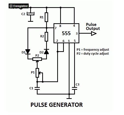
A complete description here
https://www.electroschematics.com/pulse-generator-with-555/
Jagau
- Liked by
-
-
-
-
- and 2 others

Wistiti
posted this
28 December 2022
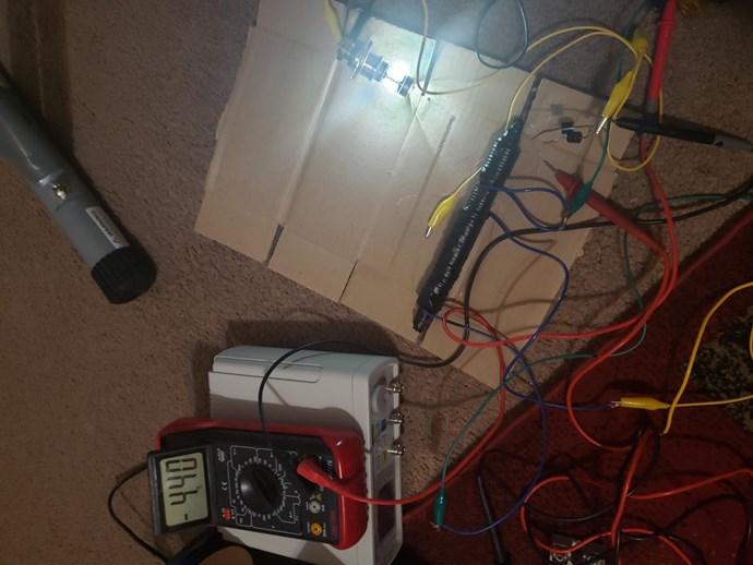
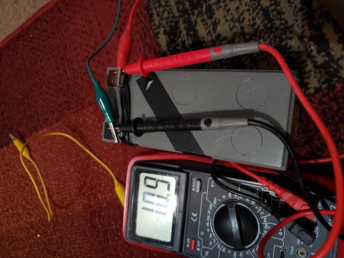
Hi freind! Im still here but with few little times for experience. Here are some pictures of my next experience.
- Liked by
-

-

-
-
- and 1 others
OriginalSkywatcher
posted this
28 December 2022
Hi all, Hi wistiti, looks good, I await further details of what you are working on. I also, started some more experiments. More like, refreshing my mind on all this stuff. Though as always, I see and get the effects we are looking for, with a device built in a day. Will be here, keeping an eye on this thread. peace love light
- Liked by
-
-
-
-
- and 1 others
Wistiti
posted this
04 January 2023
Hi Sky!
Nice to see you are still here.
For now, nothing new to share. I'm just playing around with my old stuff. Trying to add new idea around it or look at it with a different point of view. Who knows, some new idea might pop up!
🌞
- Liked by
-
-
-

We're Light Years Ahead!

Our Above Unity Machines:
Recomended Protocol:
Members Online:
No one online at the moment
What is a Scalar:
In physics, scalars are physical quantities that are unaffected by changes to a vector space basis. Scalars are often accompanied by units of measurement, as in "10 cm". Examples of scalar quantities are mass, distance, charge, volume, time, speed, and the magnitude of physical vectors in general.
You need to forget the Non-Sense that some spout with out knowing the actual Definition of the word Scalar! Some people talk absolute Bull Sh*t!
The pressure P in the formula P = pgh, pgh is a scalar that tells you the amount of this squashing force per unit area in a fluid.
A Scalar, having both direction and magnitude, can be anything! The Magnetic Field, a Charge moving, yet some Numb Nuts think it means Magic Science!
Start Here:
Message from God:
Hello my children. This is Yahweh, the one true Lord. You have found creation's secret. Now share it peacefully with the world.
Ref: Message from God written inside the Human Genome
God be in my head, and in my thinking.
God be in my eyes, and in my looking.
God be in my mouth, and in my speaking.
Oh, God be in my heart, and in my understanding.
Your Support:
More than anything else, your contributions to this forum are most important! We are trying to actively get all visitors involved, but we do only have a few main contributors, which are very much appreciated! If you would like to see more pages with more detailed experiments and answers, perhaps a contribution of another type maybe possible:
They REFUSE to tell me why!
The content I am sharing is not only unique, but is changing the world as we know it! Please Support Us!
Thank You So Much!
Browse by Category:
Weeks High Earners:
-
Chris
350
-
---open-tesla-research.jpg?width=20&crop=0,0,20,20) akoteles
100
akoteles
100
-
Arya 100
-
 Gucio_81
92
Gucio_81
92
-
 FringeIdeas
90
FringeIdeas
90
-
thaelin 50
-
skywatcher 20
-
anarsu 20


The great Nikola Tesla:

Ere many generations pass, our machinery will be driven by a power obtainable at any point of the universe. This idea is not novel. Men have been led to it long ago by instinct or reason. It has been expressed in many ways, and in many places, in the history of old and new. We find it in the delightful myth of Antheus, who drives power from the earth; we find it among the subtle speculations of one of your splendid mathematicians, and in many hints and statements of thinkers of the present time. Throughout space there is energy. Is this energy static or kinetic? If static, our hopes are in vain; if kinetic - and this we know it is for certain - then it is a mere question of time when men will succeed in attaching their machinery to the very wheelwork of nature.
Experiments With Alternate Currents Of High Potential And High Frequency (February 1892).
