Hey Guys,
Thanks for posting this Aetherholic:
I was asked by PM if the shunt resistor has any inductance at the frequency being used.
This question is a reasonable question to ask! However, the method of Measuring Current, is Industry Standard Precision Measurement! So Aetherholic's response:
It is absolutely correct to ask this question.
The answer is it is a manganin copper shunt with negligable inductance and an almost flat frequency response up to 40kHz. It is the most accurate way to measure high frequency AC current.
Is a very important response that I would like to add some more information on!
I think it is important to note, all Electrical Components have:
- Resistance / Impedance
- Inductance
- Capacitance
Sometimes, some or all of these values can be very small!
For example, the following manganin copper shunt, which may not be the same as Aetherholics, has very specific very precise Ratings:
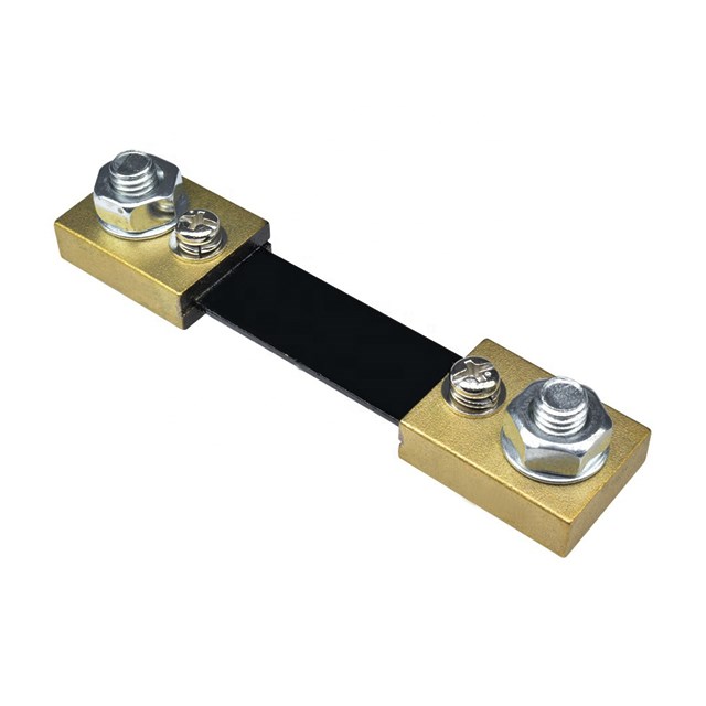
- Application: Electrical, Meter, Current Measurement
- Rated Power: 1~10W
- Resistance: 100~1000μΩ, 20
- Supplier Type: Original manufacturer
- Tolerance: 40ppm
- Technology: Metal Alloy
- Package Type: Through Hole
- Resistance Tolerance: 0.1%
- Temperature Coefficient: 40ppm
- Operating Temperature: -45℃~125℃
These Shunt Resistors are very precisely Rated! As you can see, there is a very narrow margin of Error: 0.1% Normally the value of Inductance is also provided, but not in this case, however, a Resistive Shunt this large, will have a very tiny Inductance.
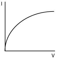
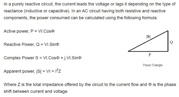
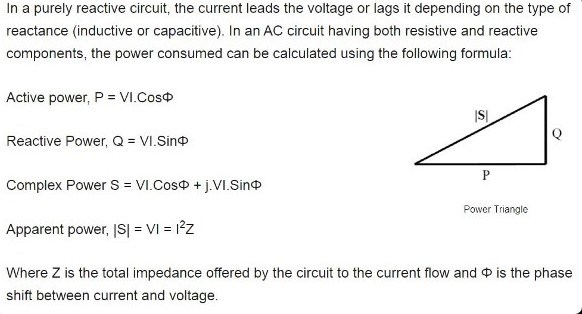
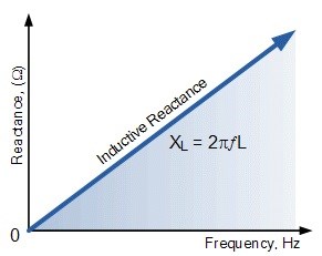
As we know, the Impedance of an Inductor increases with Frequency: Note Omega ω is the increasing Frequency f:
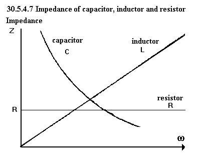
However, the DC Resistance does not! Normally!
Resistance is not Inductance! However, Resistance R, measured in Ohms Ω, is related to Impedance Z, which is also measured in Ohms Ω. We have been through this before on Captainloz's thread! Care must be taken not to make silly mistakes when making assumptions! Impedance is Inductive Reactance XL, and Capacitive Reactance XC, and Inductive Reactance changes with Frequency:
Assuming this Increase, is just stupidity!
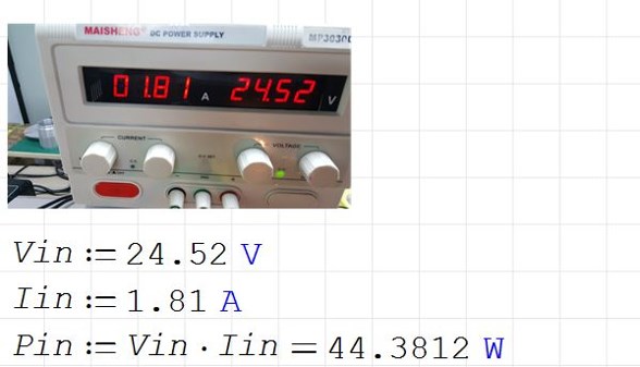
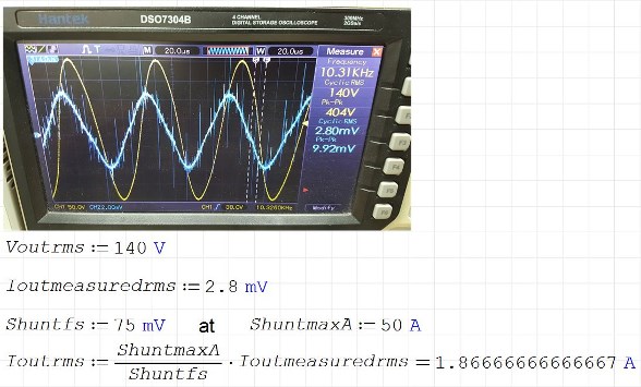
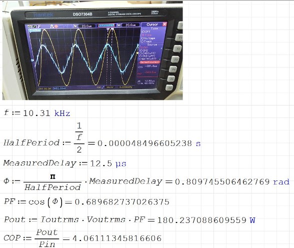
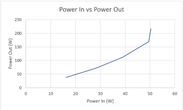
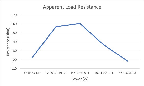
Simple checks can verify what you are Measuring, measuring the Average Output Voltage, or RMS if the Output is Sinusoidal, then one can calculate the Output Current.
For Series Load Resistance:
ResistanceTotal = R1 + R2 + R3 + ... Rn
For Parallel Load Resistances
1 / ResistanceTotal = 1 / R1 + 1 / R2 + 1 / R3 + ... 1 / Rn
These simple Equations verify the Current Measurement! Which we did as part of our due diligence!
It is worth noting, if there is any discrepancy over the Inductive Reactance XL, across the Precision Shunt Resistor, will see the very same Error on the Input to Output anyway! In other words, at the same Frequency, if the Output Shunt resistor has a 2% Margin of Error, then the Input will also have a 2% Margin of Error also!
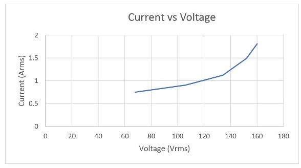
As the Frequency Increases, the Inductive Reactance Increases, then as a result, via Ohms Law, I = V / R, the Current Measured must come down on both Input and Output Precision Measurement Resistors!
Truth of the matter is, there are some that can not fathom what we are doing! We are truly Light Years Ahead of the Others!
Thank You Aetherholic for bringing this up before Numpty's start jumping to ridiculous conclusions!
Best Wishes,
Chris