Arduino Aquaponics

  • 1.3K Views
  • Last Post 03 September 2018
  • Topic Is Solved
Marathonman posted this 27 May 2018

I don't know if anyone is interested in growing their own food and vegetables but this Aquaponic system i have built works just perfect. i am i newbie when it comes to programming and i am sure someone could do better but all i can say is it works and works very darn well. i studied Arduino platform for a few weeks and the two programs are the start up which runs for 10 days and the run program cycles 8.5 times in 24 hours.

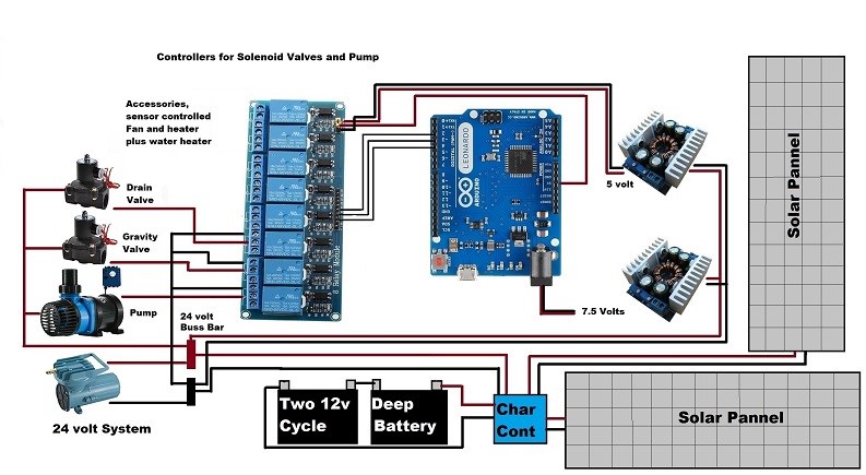
it uses AC as back up only utilizing the light out function on a charge controller at 24 volts and two solar panels supplying all the power to the system. it has an air pump that is on 24/7 with a water pump on for 8 times in 24 hours and two 24 volt solenoid valves on for 15 minutes every 2 hours. the whole system only takes 60 watts for the air pump @ 24/7, the water pump @ 80 watts for 5 minutes every 2 plus hours and each solenoid valve are on at separate times for 15 minutes every 2 plus hours @ 12.5 watts each.

i have built two systems near my house for people and they are very happy i designed the system and helped them build it. i made a few bucks off of it but not much. and yes i know aerate is spelled wrong.

the system in the video was before i installed it into it's permanent home. the LED lights indicate that stage complete which is LED 1 -5 with the red blinking LED shown upcoming stage. turning the sound up you will hear the relays clicking on and off working flawlessly.


Marathonman

  • Liked by
  • Chris
  • Zanzal
Order By: Standard | Newest | Votes
Marathonman posted this 27 May 2018

The start up program is designed for the colonization of good bacteria. instead of taking up to three months to form good bacterial i  have taken it down to 10 to 11 days and here is how.

cycle the water for for three days to rid the water of chlorine adding vitamine C, add a bottle of food grade ammonia then circulate for one day. add bottle of Nitrifying  bacteria and circulate for 6 to 7 days then test for colonization . bugs took both times i built the system so then you can add the fish and plants making sure no soil is introduced to the system. wash off all soil from the roots before transplanting to the Aquaponic system as soil has bad bacterial and diseases in it and can harm the eco system.

when our world goes shit very soon people need to learn how to grow their own food to survive and this system is a good way to do it.

this method of nitrifying the system was studied and conducted by me and verified to work 100 %.


Marathonman

Attached Files

  • Liked by
  • Zanzal
  • Chris
Marathonman posted this 27 May 2018

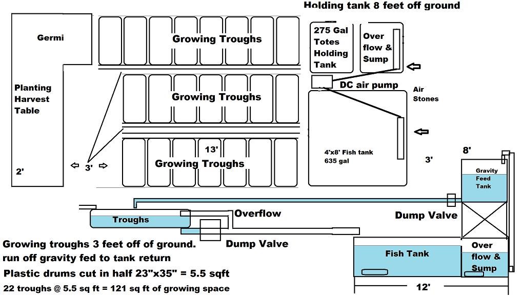
The system is what you call an ebb and flow system. the pump pumps the water into the overhead tank then shuts off. then the flood valve opens and floods the troughs from gravity. the system soaks for two hours allowing the nutrient to be absorbed by the plants then the drain valve opens and drains the clean water into the fish tank then the overflow tank. the water then sits for 15 minutes to aerate which is reoxygenating the water for the next cycle.

the above pic in the previous post is the cycle of Aquaponics system. the pic below is the actual system i built.

Marathonman

  • Liked by
  • Zanzal
  • Chris
Marathonman posted this 27 May 2018

Each system can be increased or decreased in size according to your own desires as the gravity feed tank can hold up to 275 gallons. once the growing troughs are filled with growing media it will hold around 5 to 7 gallons of water so many growing troughs can be added in the range of 39 to 55 media beds depending on the size of the grow media.

the electronics involved are the pic below which were designed by me and me alone. i am sure you could alter the system to your liking.


Marathonman

  • Liked by
  • Chris
Marathonman posted this 27 May 2018

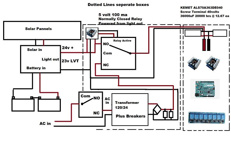
As you can see from circuit diagrams the AC transformer is shut out of the system and not used until the LVT (Low Voltage Threshold ) is crossed which when designed properly will not ever be used if enough battery amp hour rating is in the range of 150 to 200 Ah.

if the AC should kick in the surge to the system will be minimal because of the four large 24v DC caps and the use of an inductor. also the use of circuitry to kick on at the zero crossing will help minimize surge currant which is incorporated into the AC relay.

the system uses the 24 volt light out function of the charge controller that activates two low voltage relays from NC to NO keeping the two systems completely separate. also the two buck power supplies keep the Arduino and the relays completely separate through Optoisolation also in case of an accident or short of any of the systems minimizing the chance of whole system failure.

this system can be completely Autonomous  when the Figuera system is complete or the 1932 Coutier device is used with these systems.

if anyone has any questions please feel free to ask or post your Aquaponic systems designs as this is about the very survival of the human race not corporate takeover of your lives.

Marathonman

  • Liked by
  • Chris
Marathonman posted this 27 May 2018

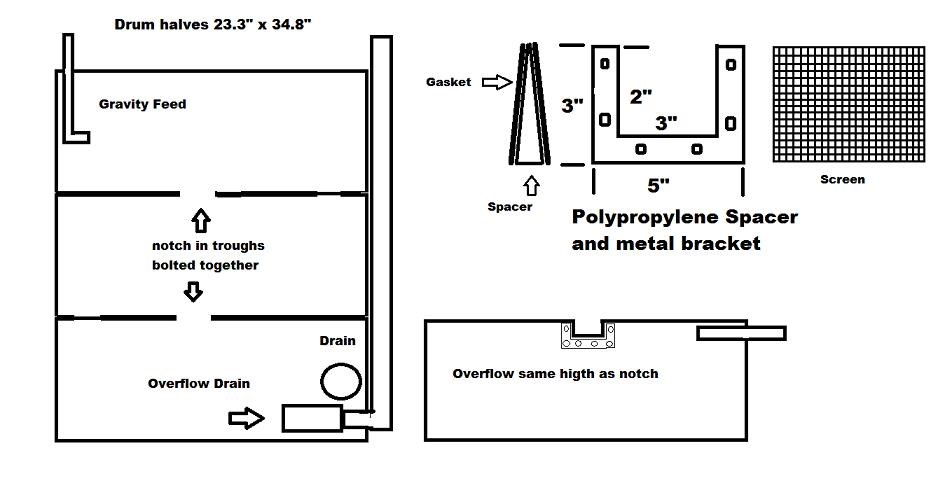
There is multiple ways to run the piping from the gravity feed tank to the troughs. you can either run piping to all the troughs to feed individually but you will also have to have separate overflow and drains for each trough. you can also do as i did by cutting the drums and adding spacers connecting each trough together  so when the first drum fills it overflows into the next drum and so on until the last drum is filled and overflows past the valve into the fish tank to the overflow sump tote. this decreases the amount of piping needed and all drum drains are connected to one trough drain valve for less complexity.

here is a pic of the spacers used to connect the half drum growing troughs together. the two inch by three inch grove is plenty to keep the troughs from overflowing draining into the next then out the overflow drain.

Marathonman

  • Liked by
  • Chris
Marathonman posted this 27 May 2018

Both systems have Tilapia because they are very hardy in Texas hot weather. they are aggressive, fast growers, taste good and can handle not so good water conditions.

if you live in colder weather i would suggest Trout as they can handle extreme cold conditions, grow fast and taste excellent.

always be aware the the plastics in above ground pools may not always be good for the fish and may not always last that long. building a tank lined with special blue paint specifically designed for fish tanks or food grade totes are always optimal choice. also always use approved piping for water transfer as the regular will kill fish being toxic.

in the picture of the system the tank is 8 feet but two feet has a very small net across the tank for fingerlings so when you harvest the tilapia the larger fingerlings can be put into the main tank area. tilapia as i said are aggressive and will eat the fingerlings if to small thus wiping out the fingerlings in a matter of minutes.

the use of a whole pool as the fish tank would be for a very, very large system and not recommended for anything less.

This is one of my many hobbies in which i know quite a lot about through years of studying and back yard testing. i also build and service computers, build firewalls, routers, networking homes/small businesses and such for people i happen to meet through casual conversations at grocery stores and such. i also dabble in board design using DipTrace. i  do industrial sewing making car, motor cycle and BBQ covers as i was a parachute rigger in the military. i am a wiz at home audio and video using surround sound setups. making multi-screen video game set ups is also fun. my best setup was a three projector video game system using a 30 x 10 foot wall as the screen. the dude cried when i turned it on and played CALL OF DUTY MW3 with a wireless controller. i am also great with all hand tools with wood and metal lath work. i can fix just about anything especially if it has moving parts. i work a little on cars to,  like breaks, rotor replacement and the like. good carpenter also. 

Marathonman

  • Liked by
  • Chris
Marathonman posted this 29 May 2018

It is actually quite easy to grow anything in an Aquaponic system, having the perfect system with fish and plants using good bacteria to break down the Ammonia to nitrogen the  plants thrive on.

below is a picture of two chocolate mint plants. one was grown in a pot with water from the hose and the other was watered from an Aquaponic system.

it is hard to believe both plants are six to eight weeks old.

Marathonman

  • Liked by
  • Chris
Marathonman posted this 29 May 2018

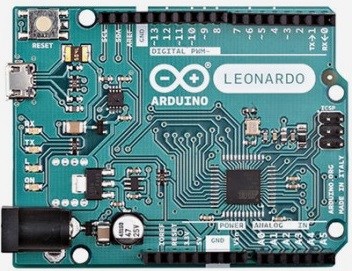
The newest Arduino IDE is 1.8.5 can be downloaded from here https://www.arduino.cc/

It can be used to program your Arduino board in which the two basic programs can be used on just about any Arduino board.

the Arduino platform is a great way to cycle your Aquaponics system as it being very low power and the optical isolated relays provide protection and a load up to 10 amp.


Marathonman 

  • Liked by
  • Chris
Marathonman posted this 30 May 2018

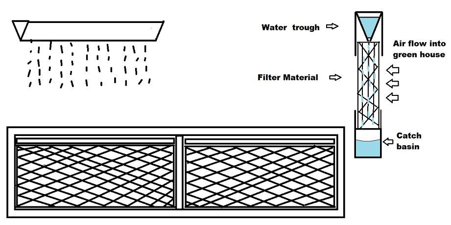
The system i have provided can also be used with just an AC step down transformer to 24 volts which the transformer is not very expensive.   24 volts @ 10 amp is plenty of headroom for this system and can leave room for a cooling system like the one below.

having 24 volt exhaust fans in the upper area  with louvers with an evaporative water trickle system in the lower half of your green house will keep things cool during the hottest days in summer and is very energy efficient to boot. the system can be incorporated with ease and minimal electronics which are everywhere on the net.

the pic below is the evap system that is easily incorporated near the ground level using a cheap 24 volt pump to pump the water from the catch basin to the upper trickle trough.


Marathonman

Marathonman posted this 30 May 2018

The pins can be changed in the program to match that of your Arduino used but just be aware they have to match when being declared or you will get an error when compiling from code to machine code uploading to the Arduino. the pump times and the valve times can all be changed to your liking which changes the cycle times. when cycling the system i would do 30 minutes for each stage to be on the safe side allowing the gravity feed  and troughs a chance to completely drain.

Marathonman

Marathonman posted this 30 May 2018

This is the RUN program used thereafter.

[code]
/* This sketch controls an Ebb and Flow Aquaponic system utalizing three relays and led lights for visualization
   of currant stage and upcoming stage. relay 1 water pump pin 2, relay 2 gravity feed solenoid valve pin 3 and
   relay 3 drain solenoid valve pin 4.
   1-5 led's indicate stage complete pin's 5-9, led 6 is upcoming stage indicator pin 13.
   stage 1 pump, stage 2 flood, stage 3 soak, stage 4 drain and stage 5 aerate.

   Relays power to opto's are all tied together so the low pin connected to the Arduino has to go low before the 
   relay will turn on. high means off, low means on so in setup declare them high before running loop.

   created on 11-15-2017
   Marathonman
 */

   int RELAY1 = 2;                 // assigning pin 2 of the Arduino for relay 1 
   int RELAY2 = 3;                 // assigning pin 3 of the Arduino for relay 2 
   int RELAY3 = 4;                 // assigning pin 4 of the Arduino for relay 3 
   int led = 13;                   // assinging pin 13 as led stage indication
   int led2 = 5;                   // assigning first stage led to pin 5 
   int led3 = 6;                   // assigning second stage led to pin 6
   int led4 = 7;                   // assigning third stage led to pin 7
   int led5 = 8;                   // assigning fourth stage led to pin 8
   int led6 = 9;                   // assigning fifth stage led to pin 9

  void setup()
   {
   pinMode(RELAY1,    OUTPUT);     // initializing the pin 2 of the Arduino as output
   pinMode(RELAY2,    OUTPUT);     // initializing the pin 3 of the Arduino as output
   pinMode(RELAY3,    OUTPUT);     // initializing the pin 4 of the Arduino as output
   pinMode(led,       OUTPUT);     // initialize LED pin 13 as an output
   pinMode(led2,      OUTPUT);     // initializing first stage led as output
   pinMode(led3,      OUTPUT);     // initializing second stage led as output
   pinMode(led4,      OUTPUT);     // initializing third stage led as output
   pinMode(led5,      OUTPUT);     // initializing fourth led as output
   pinMode(led6,      OUTPUT);     // initializing fifth led as output
   digitalWrite(RELAY1, HIGH);     // This will Turn Relay 1 Off
   digitalWrite(RELAY2, HIGH);     // This will Turn Relay 2 Off
   digitalWrite(RELAY3, HIGH);     // This will Turn Relay 3 Off
   }

  void loop()
   {
   digitalWrite(led,    HIGH);     // turn the LED on (HIGH is the voltage level)
   delay(250);                     // wait for a quarter second
   digitalWrite(led,     LOW);     // turn the LED off by making the voltage LOW
   delay(2000);                    // wait for two seconds
   digitalWrite(led,    HIGH);     // turn the LED on 
   delay(250);                     // wait for a quarter second
   digitalWrite(led,     LOW);     // turn the LED off
   delay(2000);                    // wait for two seconds
   digitalWrite(led,    HIGH);     // turn the LED on 
   delay(250);                     // wait for a quarter second
   digitalWrite(led,     LOW);     // turn the LED off
   digitalWrite(RELAY1,  LOW);     // This will Turn relay 1 on
   delay(276000);                  // Wait for 276 seconds
   digitalWrite(RELAY1, HIGH);     // This will Turn Relay 1 Off
   delay(250);                     // wait for a quarter second
   digitalWrite(led2,   HIGH);     // This will indicate stage 1 complete
   digitalWrite(led,    HIGH);     // turn the LED on 
   delay(250);                     // wait for a quarter second
   digitalWrite(led,     LOW);     // turn the LED off 
   delay(250);                     // wait for a quarter second
   digitalWrite(led,    HIGH);     // turn the LED on 
   delay(250);                     // wait for a quarter second
   digitalWrite(led,     LOW);     // turn the LED off
   delay(2000);                    // wait for two seconds
   digitalWrite(led,    HIGH);     // turn the LED on
   delay(250);                     // wait for a quarter second
   digitalWrite(led,     LOW);     // turn the LED off 
   delay(250);                     // wait for a quarter second
   digitalWrite(led,    HIGH);     // turn the LED on 
   delay(250);                     // wait for a quarter second
   digitalWrite(led,     LOW);     // turn the LED off 
   delay(2000);                    // wait for two seconds
   digitalWrite(led,    HIGH);     // turn the LED on 
   delay(250);                     // wait for a quarter second
   digitalWrite(led,     LOW);     // turn the LED off
   delay(250);                     // wait for a quarter second
   digitalWrite(led,    HIGH);     // turn the LED on 
   delay(250);                     // wait for a quarter second
   digitalWrite(led,     LOW);     // turn the LED off 
   digitalWrite(RELAY2,  LOW);     // This will Turn relay 2 on
   delay(900000);                  // Wait for 900 seconds
   digitalWrite(RELAY2, HIGH);     // This will Turn Relay 2 Off
   delay(250);                     // wait for a quarter second
   digitalWrite(led3,   HIGH);     // This will indicate stage 2 complete
   digitalWrite(led,    HIGH);     // turn the LED on
   delay(250);                     // wait for a quarter second
   digitalWrite(led,     LOW);     // turn the LED off
   delay(250);                     // wait for a quarter second
   digitalWrite(led,    HIGH);     // turn the LED on 
   delay(250);                     // wait for a quarter second
   digitalWrite(led,     LOW);     // turn the LED off
   delay(250);                     // wait for a quarter second 
   digitalWrite(led,    HIGH);     // turn the LED on 
   delay(250);                     // wait for a quarter second
   digitalWrite(led,     LOW);     // turn the LED off 
   delay(2000);                    // wait for two seconds
   digitalWrite(led,    HIGH);     // turn the LED on 
   delay(250);                     // wait for a quater second
   digitalWrite(led,     LOW);     // turn the LED off 
   delay(250);                     // wait for a quarter second
   digitalWrite(led,    HIGH);     // turn the LED on 
   delay(250);                     // wait for a quarter second
   digitalWrite(led,     LOW);     // turn the LED off 
   delay(250);                     // wait for a quarter second 
   digitalWrite(led,    HIGH);     // turn the LED on 
   delay(250);                     // wait for a quarter second
   digitalWrite(led,     LOW);     // turn the LED off 
   delay(2000);                    // wait for two second
   digitalWrite(led,    HIGH);     // turn the LED on 
   delay(250);                     // wait for a quarter second
   digitalWrite(led,     LOW);     // turn the LED off 
   delay(250);                     // wait for a quarter second
   digitalWrite(led,    HIGH);     // turn the LED on 
   delay(250);                     // wait for a quarter second
   digitalWrite(led,     LOW);     // turn the LED off 
   delay(250);                     // wait for a Quarter second 
   digitalWrite(led,    HIGH);     // turn the LED on
   delay(250);                     // wait for a quarter second
   digitalWrite(led,     LOW);     // turn the LED off 
   delay(7200000);                 // Wait for 7200 seconds
   digitalWrite(led4,   HIGH);     // This will indicate stage 3 complete
   digitalWrite(led,    HIGH);     // turn the LED on
   delay(250);                     // wait for a quarter second
   digitalWrite(led,     LOW);     // turn the LED off
   delay(250);                     // wait for a quarter second
   digitalWrite(led,    HIGH);     // turn the LED on 
   delay(250);                     // wait for a quarter second
   digitalWrite(led,     LOW);     // turn the LED off
   delay(250);                     // wait for a quarter second 
   digitalWrite(led,    HIGH);     // turn the LED on 
   delay(250);                     // wait for a quarter second 
   digitalWrite(led,     LOW);     // turn the LED off
   delay(250);                     // wait for a quarter second
   digitalWrite(led,    HIGH);     // turn the LED on 
   delay(250);                     // wait for a quater second
   digitalWrite(led,     LOW);     // turn the LED off 
   delay(2000);                    // wait for two seconds
   digitalWrite(led,    HIGH);     // turn the LED on 
   delay(250);                     // wait for a quarter second
   digitalWrite(led,     LOW);     // turn the LED off 
   delay(250);                     // wait for a quarter second 
   digitalWrite(led,    HIGH);     // turn the LED on 
   delay(250);                     // wait for a quarter second
   digitalWrite(led,     LOW);     // turn the LED off 
   delay(250);                     // wait for a quarter second
   digitalWrite(led,    HIGH);     // turn the LED on 
   delay(250);                     // wait for a quarter second
   digitalWrite(led,     LOW);     // turn the LED off 
   delay(250);                     // wait for a quarter second
   digitalWrite(led,    HIGH);     // turn the LED on 
   delay(250);                     // wait for a quarter second
   digitalWrite(led,     LOW);     // turn the LED off 
   delay(2000);                    // wait for two seconds 
   digitalWrite(led,    HIGH);     // turn the LED on
   delay(250);                     // wait for a quarter second
   digitalWrite(led,     LOW);     // turn the LED off 
   delay(250);                     // wait for a quarter second
   digitalWrite(led,    HIGH);     // turn the LED on 
   delay(250);                     // wait for a quarter second
   digitalWrite(led,     LOW);     // turn the LED off 
   delay(250);                     // wait for a quarter second
   digitalWrite(led,    HIGH);     // turn the LED on 
   delay(250);                     // wait for a quarter second
   digitalWrite(led,     LOW);     // turn the LED off
   delay(250);                     // wait for a quarter second 
   digitalWrite(led,    HIGH);     // turn the LED on 
   delay(250);                     // wait for a quarter second
   digitalWrite(led,     LOW);     // turn the LED off
   digitalWrite(RELAY3,  LOW);     // This will Turn relay 3 on
   delay(900000);                  // Wait for 900 seconds
   digitalWrite(RELAY3, HIGH);     // This will Turn Relay 3 Off
   delay(250);                     // wait for a quarter second
   digitalWrite(led5,   HIGH);     // This will indicate stage 4 complete
   digitalWrite(led,    HIGH);     // turn the LED on
   delay(250);                     // wait for a quarter second
   digitalWrite(led,     LOW);     // turn the LED off
   delay(250);                     // wait for a quarter second
   digitalWrite(led,    HIGH);     // turn the LED on 
   delay(250);                     // wait for a quarter second
   digitalWrite(led,     LOW);     // turn the LED off
   delay(250);                     // wait for a quarter second 
   digitalWrite(led,    HIGH);     // turn the LED on 
   delay(250);                     // wait for a quarter second 
   digitalWrite(led,     LOW);     // turn the LED off
   delay(250);                     // wait for a quarter second
   digitalWrite(led,    HIGH);     // turn the LED on 
   delay(250);                     // wait for a quater second
   digitalWrite(led,     LOW);     // turn the LED off
   delay(250);                     // wait for a quarter second
   digitalWrite(led,    HIGH);     // turn the LED on 
   delay(250);                     // wait for a quater second
   digitalWrite(led,     LOW);     // turn the LED off 
   delay(2000);                    // wait for two seconds
   digitalWrite(led,    HIGH);     // turn the LED on 
   delay(250);                     // wait for a quarter second
   digitalWrite(led,     LOW);     // turn the LED off 
   delay(250);                     // wait for a quarter second 
   digitalWrite(led,    HIGH);     // turn the LED on 
   delay(250);                     // wait for a quarter second
   digitalWrite(led,     LOW);     // turn the LED off 
   delay(250);                     // wait for a quarter second
   digitalWrite(led,    HIGH);     // turn the LED on 
   delay(250);                     // wait for a quarter second
   digitalWrite(led,     LOW);     // turn the LED off 
   delay(250);                     // wait for a quarter second
   digitalWrite(led,    HIGH);     // turn the LED on
   delay(250);                     // wait for a quarter second
   digitalWrite(led,     LOW);     // turn the LED off 
   delay(250);                     // wait for a quarter second
   digitalWrite(led,    HIGH);     // turn the LED on 
   delay(250);                     // wait for a quater second 
   digitalWrite(led,     LOW);     // turn the LED off 
   delay(2000);                    // wait for two seconds 
   digitalWrite(led,    HIGH);     // turn the LED on
   delay(250);                     // wait for a quarter second
   digitalWrite(led,     LOW);     // turn the LED off 
   delay(250);                     // wait for a quarter second
   digitalWrite(led,    HIGH);     // turn the LED on 
   delay(250);                     // wait for a quarter second
   digitalWrite(led,     LOW);     // turn the LED off 
   delay(250);                     // wait for a quarter second
   digitalWrite(led,    HIGH);     // turn the LED on 
   delay(250);                     // wait for a quarter second
   digitalWrite(led,     LOW);     // turn the LED off
   delay(250);                     // wait for a quarter second 
   digitalWrite(led,    HIGH);     // turn the LED on 
   delay(250);                     // wait for a quarter second
   digitalWrite(led,     LOW);     // turn the LED off
   delay(250);                     // wait for a quarter second
   digitalWrite(led,    HIGH);     // turn the LED on 
   delay(250);                     // wait for a quarter second
   digitalWrite(led,     LOW);     // turn the LED off
   delay(900000);                  // Wait for 900 seconds
   digitalWrite(led6,   HIGH);     // This will indicate stage 5 complete
   delay(1000);                    // wait for a two seconds
   digitalWrite(led,    HIGH);     // turn the LED on 
   delay(500);                     // wait for half  second
   digitalWrite(led,     LOW);     // turn the LED off
   delay(500);                     // wait for half second
   digitalWrite(led,    HIGH);     // turn the LED on 
   delay(500);                     // wait for half second
   digitalWrite(led,     LOW);     // turn the LED off 
   delay(500);                     // wait for half second
   digitalWrite(led,    HIGH);     // turn the LED on 
   delay(500);                     // wait for half second
   digitalWrite(led,     LOW);     // turn the LED off 
   delay(500);                     // wait for half second
   digitalWrite(led,    HIGH);     // turn the LED on 
   delay(500);                     // wait for half second
   digitalWrite(led,     LOW);     // turn the LED off 
   delay(500);                     // wait for half second
   digitalWrite(led,    HIGH);     // turn the LED on 
   delay(500);                     // wait for half second
   digitalWrite(led,     LOW);     // turn the LED off 
   delay(500);                     // wait for half second
   digitalWrite(led6,    LOW);     // turns led off
   delay(250);                     // wait a quarter second
   digitalWrite(led5,    LOW);     // turns led off
   delay(250);                     // wait a quarter second
   digitalWrite(led4,    LOW);     // turns led off
   delay(250);                     // wait a quarter second
   digitalWrite(led3,    LOW);     // turns led off
   delay(250);                     // wait a quarter second
   digitalWrite(led2,    LOW);     // turns led off
   delay(1000);                    // wait 1 second

   }
[/code]

  • Liked by
  • Chris
Marathonman posted this 30 May 2018

This is the startup program used for 10 to 11 days to establish the nitifying bacteria in the system i discussed in a previous post.

[code]

/* This sketch controls an Ebb and Flow Aquaponic system utilizing three relays and led lights for visualization
   of currant stage and upcoming stage. relay 1 water pump pin 2, relay 2 gravity feed solenoid valve pin 3 and
   relay 3 grow bed drain solenoid valve pin 4.
   1-5 led's indicate stage complete pin's 5-9, led 6 is upcoming stage indicator pin 13.
   stage 1 pump, stage 2 flood, stage 3 soak, stage 4 drain and stage 5 aerate.

   Relays power to opto's are all tied together so the low pin connected to the Arduino has to go low
   before the relay will turn on. high means off, low means on so in setup declare them high before running loop.

   created on 11-15-2017
   Marathonman
 */

   int RELAY1 = 2;                 // assigning pin 2 of the Arduino for relay 1 
   int RELAY2 = 3;                 // assigning pin 3 of the Arduino for relay 2 
   int RELAY3 = 4;                 // assigning pin 4 of the Arduino for relay 3 
   int led = 13;                   // assinging pin 13 as led stage indication
   int led2 = 5;                   // assigning first stage led to pin 5 
   int led3 = 6;                   // assigning second stage led to pin 6
   int led4 = 7;                   // assigning third stage led to pin 7
   int led5 = 8;                   // assigning fourth stage led to pin 8
   int led6 = 9;                   // assigning fifth stage led to pin 9


  void setup()
   {
   pinMode(RELAY1,    OUTPUT);     // initialize pin 2 of the Arduino as output
   pinMode(RELAY2,    OUTPUT);     // initialize pin 3 of the Arduino as output
   pinMode(RELAY3,    OUTPUT);     // initialize pin 4 of the Arduino as output
   pinMode(led,       OUTPUT);     // initialize LED pin 13 as an output
   pinMode(led2,      OUTPUT);     // initialize first stage led as output
   pinMode(led3,      OUTPUT);     // initialize second stage led as output
   pinMode(led4,      OUTPUT);     // initialize third stage led as output
   pinMode(led5,      OUTPUT);     // initialize fourth stage led as output
   pinMode(led6,      OUTPUT);     // initialize fifth stage led as output
   digitalWrite(RELAY1, HIGH);     // This will Turn Relay 1 Off
   digitalWrite(RELAY2, HIGH);     // This will Turn Relay 2 Off
   digitalWrite(RELAY3, HIGH);     // This will Turn Relay 3 Off
   }

  void loop()
   {
   digitalWrite(led,    HIGH);     // turn the LED on (HIGH is the voltage level)
   delay(250);                     // wait for a quarter second
   digitalWrite(led,     LOW);     // turn the LED off (LOW is the voltage level)
   delay(2000);                    // wait for two seconds
   digitalWrite(led,    HIGH);     // turn the LED on 
   delay(250);                     // wait for a quarter second
   digitalWrite(led,     LOW);     // turn the LED off
   delay(2000);                    // wait for two seconds
   digitalWrite(led,    HIGH);     // turn the LED on 
   delay(250);                     // wait for a quarter second
   digitalWrite(led,     LOW);     // turn the LED off
   delay(250);                     // wait for a quarter second
   digitalWrite(RELAY1,  LOW);     // This will Turn relay 1 on
   delay(300000);                  // Wait for 300 seconds
   digitalWrite(RELAY1, HIGH);     // This will Turn Relay 1 Off
   delay(250);                     // wait for a quarter second
   digitalWrite(led2,   HIGH);     // This will indicate stage 1 complete
   digitalWrite(led,    HIGH);     // turn the LED on 
   delay(250);                     // wait for a quarter second
   digitalWrite(led,     LOW);     // turn the LED off 
   delay(250);                     // wait for a quarter second
   digitalWrite(led,    HIGH);     // turn the LED on 
   delay(250);                     // wait for a quarter second
   digitalWrite(led,     LOW);     // turn the LED off
   delay(2000);                    // wait for two seconds
   digitalWrite(led,    HIGH);     // turn the LED on
   delay(250);                     // wait for a quarter second
   digitalWrite(led,     LOW);     // turn the LED off 
   delay(250);                     // wait for a quarter second
   digitalWrite(led,    HIGH);     // turn the LED on 
   delay(250);                     // wait for a quarter second
   digitalWrite(led,     LOW);     // turn the LED off 
   delay(2000);                    // wait for two seconds
   digitalWrite(led,    HIGH);     // turn the LED on 
   delay(250);                     // wait for a quarter second
   digitalWrite(led,     LOW);     // turn the LED off
   delay(250);                     // wait for a quarter second
   digitalWrite(led,    HIGH);     // turn the LED on 
   delay(250);                     // wait for a quarter second
   digitalWrite(led,     LOW);     // turn the LED off
   delay(250);                     // wait for a quarter second 
   digitalWrite(RELAY2,  LOW);     // This will Turn relay 2 on
   delay(900000);                  // Wait for 900 seconds
   digitalWrite(RELAY2, HIGH);     // This will Turn Relay 2 Off
   delay(250);                     // wait for a quarter second
   digitalWrite(led3,   HIGH);     // This will indicate stage 2 complete
   digitalWrite(led,    HIGH);     // turn the LED on
   delay(250);                     // wait for a quarter second
   digitalWrite(led,     LOW);     // turn the LED off
   delay(250);                     // wait for a quarter second
   digitalWrite(led,    HIGH);     // turn the LED on 
   delay(250);                     // wait for a quarter second
   digitalWrite(led,     LOW);     // turn the LED off
   delay(250);                     // wait for a quarter second 
   digitalWrite(led,    HIGH);     // turn the LED on 
   delay(250);                     // wait for a quarter second
   digitalWrite(led,     LOW);     // turn the LED off 
   delay(2000);                    // wait for two seconds
   digitalWrite(led,    HIGH);     // turn the LED on 
   delay(250);                     // wait for a quater second
   digitalWrite(led,     LOW);     // turn the LED off 
   delay(250);                     // wait for a quarter second
   digitalWrite(led,    HIGH);     // turn the LED on 
   delay(250);                     // wait for a quarter second
   digitalWrite(led,     LOW);     // turn the LED off 
   delay(250);                     // wait for a quarter second 
   digitalWrite(led,    HIGH);     // turn the LED on 
   delay(250);                     // wait for a quarter second
   digitalWrite(led,     LOW);     // turn the LED off 
   delay(2000);                    // wait for two second
   digitalWrite(led,    HIGH);     // turn the LED on 
   delay(250);                     // wait for a quarter second
   digitalWrite(led,     LOW);     // turn the LED off 
   delay(250);                     // wait for a quarter second
   digitalWrite(led,    HIGH);     // turn the LED on 
   delay(250);                     // wait for a quarter second
   digitalWrite(led,     LOW);     // turn the LED off 
   delay(250);                     // wait for a Quarter second 
   digitalWrite(led,    HIGH);     // turn the LED on
   delay(250);                     // wait for a quarter second
   digitalWrite(led,     LOW);     // turn the LED off 
   delay(600000);                  // Wait for 600 seconds
   digitalWrite(led4,   HIGH);     // This will indicate stage 3 complete
   digitalWrite(led,    HIGH);     // turn the LED on
   delay(250);                     // wait for a quarter second
   digitalWrite(led,     LOW);     // turn the LED off
   delay(250);                     // wait for a quarter second
   digitalWrite(led,    HIGH);     // turn the LED on 
   delay(250);                     // wait for a quarter second
   digitalWrite(led,     LOW);     // turn the LED off
   delay(250);                     // wait for a quarter second 
   digitalWrite(led,    HIGH);     // turn the LED on 
   delay(250);                     // wait for a quarter second 
   digitalWrite(led,     LOW);     // turn the LED off
   delay(250);                     // wait for a quarter second
   digitalWrite(led,    HIGH);     // turn the LED on 
   delay(250);                     // wait for a quater second
   digitalWrite(led,     LOW);     // turn the LED off 
   delay(2000);                    // wait for two seconds
   digitalWrite(led,    HIGH);     // turn the LED on 
   delay(250);                     // wait for a quarter second
   digitalWrite(led,     LOW);     // turn the LED off 
   delay(250);                     // wait for a quarter second 
   digitalWrite(led,    HIGH);     // turn the LED on 
   delay(250);                     // wait for a quarter second
   digitalWrite(led,     LOW);     // turn the LED off 
   delay(250);                     // wait for a quarter second
   digitalWrite(led,    HIGH);     // turn the LED on 
   delay(250);                     // wait for a quarter second
   digitalWrite(led,     LOW);     // turn the LED off 
   delay(250);                     // wait for a quarter second
   digitalWrite(led,    HIGH);     // turn the LED on 
   delay(250);                     // wait for a quarter second
   digitalWrite(led,     LOW);     // turn the LED off 
   delay(2000);                    // wait for two seconds 
   digitalWrite(led,    HIGH);     // turn the LED on
   delay(250);                     // wait for a quarter second
   digitalWrite(led,     LOW);     // turn the LED off 
   delay(250);                     // wait for a quarter second
   digitalWrite(led,    HIGH);     // turn the LED on 
   delay(250);                     // wait for a quarter second
   digitalWrite(led,     LOW);     // turn the LED off 
   delay(250);                     // wait for a quarter second
   digitalWrite(led,    HIGH);     // turn the LED on 
   delay(250);                     // wait for a quarter second
   digitalWrite(led,     LOW);     // turn the LED off
   delay(250);                     // wait for a quarter second 
   digitalWrite(led,    HIGH);     // turn the LED on 
   delay(250);                     // wait for a quarter second
   digitalWrite(led,     LOW);     // turn the LED off
   digitalWrite(RELAY3,  LOW);     // This will Turn relay 3 on
   delay(900000);                  // Wait for 900 seconds
   digitalWrite(RELAY3, HIGH);     // This will Turn Relay 3 Off
   delay(250);                     // wait for a quarter second
   digitalWrite(led5,   HIGH);     // This will indicate stage 4 complete
   digitalWrite(led,    HIGH);     // turn the LED on
   delay(250);                     // wait for a quarter second
   digitalWrite(led,     LOW);     // turn the LED off
   delay(250);                     // wait for a quarter second
   digitalWrite(led,    HIGH);     // turn the LED on 
   delay(250);                     // wait for a quarter second
   digitalWrite(led,     LOW);     // turn the LED off
   delay(250);                     // wait for a quarter second 
   digitalWrite(led,    HIGH);     // turn the LED on 
   delay(250);                     // wait for a quarter second 
   digitalWrite(led,     LOW);     // turn the LED off
   delay(250);                     // wait for a quarter second
   digitalWrite(led,    HIGH);     // turn the LED on 
   delay(250);                     // wait for a quater second
   digitalWrite(led,     LOW);     // turn the LED off
   delay(250);                     // wait for a quarter second
   digitalWrite(led,    HIGH);     // turn the LED on 
   delay(250);                     // wait for a quater second
   digitalWrite(led,     LOW);     // turn the LED off 
   delay(2000);                    // wait for two seconds
   digitalWrite(led,    HIGH);     // turn the LED on 
   delay(250);                     // wait for a quarter second
   digitalWrite(led,     LOW);     // turn the LED off 
   delay(250);                     // wait for a quarter second 
   digitalWrite(led,    HIGH);     // turn the LED on 
   delay(250);                     // wait for a quarter second
   digitalWrite(led,     LOW);     // turn the LED off 
   delay(250);                     // wait for a quarter second
   digitalWrite(led,    HIGH);     // turn the LED on 
   delay(250);                     // wait for a quarter second
   digitalWrite(led,     LOW);     // turn the LED off 
   delay(250);                     // wait for a quarter second
   digitalWrite(led,    HIGH);     // turn the LED on
   delay(250);                     // wait for a quater second
   digitalWrite(led,     LOW);     // turn the LED off
   delay(250);                     // wait for a quarter second
   digitalWrite(led,    HIGH);     // turn the LED on 
   delay(250);                     // wait for a quater second 
   digitalWrite(led,     LOW);     // turn the LED off 
   delay(2000);                    // wait for two seconds 
   digitalWrite(led,    HIGH);     // turn the LED on
   delay(250);                     // wait for a quarter second
   digitalWrite(led,     LOW);     // turn the LED off 
   delay(250);                     // wait for a quarter second
   digitalWrite(led,    HIGH);     // turn the LED on 
   delay(250);                     // wait for a quarter second
   digitalWrite(led,     LOW);     // turn the LED off 
   delay(250);                     // wait for a quarter second
   digitalWrite(led,    HIGH);     // turn the LED on 
   delay(250);                     // wait for a quarter second
   digitalWrite(led,     LOW);     // turn the LED off
   delay(250);                     // wait for a quarter second 
   digitalWrite(led,    HIGH);     // turn the LED on 
   delay(250);                     // wait for a quarter second
   digitalWrite(led,     LOW);     // turn the LED off
   delay(250);                     // wait for a quarter second
   digitalWrite(led,    HIGH);     // turn the LED on 
   delay(250);                     // wait for a quarter second
   digitalWrite(led,     LOW);     // turn the LED off
   delay(600000);                  // Wait for 600 seconds
   digitalWrite(led6,   HIGH);     // This will indicate stage 5 complete
   delay(1000);                    // wait for two seconds
   digitalWrite(led,    HIGH);     // turn the LED on 
   delay(500);                     // wait for half second
   digitalWrite(led,     LOW);     // turn the LED off
   delay(500);                     // wait for half second
   digitalWrite(led,    HIGH);     // turn the LED on 
   delay(500);                     // wait for half second
   digitalWrite(led,     LOW);     // turn the LED off 
   delay(500);                     // wait for half second
   digitalWrite(led,    HIGH);     // turn the LED on 
   delay(500);                     // wait for half second
   digitalWrite(led,     LOW);     // turn the LED off 
   delay(500);                     // wait for half second
   digitalWrite(led,    HIGH);     // turn the LED on 
   delay(500);                     // wait for half second
   digitalWrite(led,     LOW);     // turn the LED off 
   delay(500);                     // wait for half second
   digitalWrite(led,    HIGH);     // turn the LED on 
   delay(500);                     // wait for half second
   digitalWrite(led,     LOW);     // turn the LED off 
   delay(500);                     // wait for half second
   digitalWrite(led6,    LOW);     // turns led 6 off
   delay(250);                     // wait for quarter second
   digitalWrite(led5,    LOW);     // turns led 5 off
   delay(250);                     // wait for quarter second
   digitalWrite(led4,    LOW);     // turns led 4 off
   delay(250);                     // wait for quarter second
   digitalWrite(led3,    LOW);     // turns led 3 off
   delay(250);                     // wait for quarter second
   digitalWrite(led2,    LOW);     // turns led 2 off
   delay(1000);                    // wait a second
   }


[/code]

  • Liked by
  • Chris
Marathonman posted this 30 May 2018

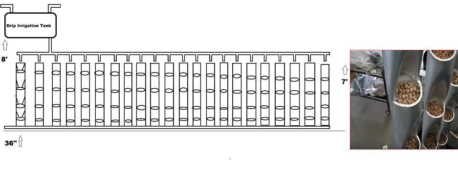
Another option on the East wall of your Aquaponic system is to utilize  the empty wall space for vertical grow beds for things like strawberries and such. i don't know to many people that don't like strawberries and it really is nice to have fresh berries for ice cream and other things, kids love em.

the vertical bed of 6 inch pipe cut and bent with a small torch to heat up the pipe and bent inward forming a closed area for grow media and drip irrigation.

below is what i have envisioned but not implemented but would be very easy to. when the water pump kicks in it fills the tank but has a return line to bleed off excess into overhead gravity feed tank. it them drips down each pipe to carry nutrients to the plants and then drains into fish tank then overflow sump tote.

This system can be scaled up or down to your liking with nothing but  a time change in the program then reloading it to the Arduino that's it.

Marathonman

Marathonman posted this 31 May 2018

The whole reason i decided to partake into this area is for one, i used to be in horticulture for years in high school and was teachers pet as i love gardening. two, the systems on line are crazy expensive and take a lot of power. so i began to study the systems out there and realized i can come up with a system that is not only energy efficient but also growth efficient at the same time. so the system i have presented is the culmination of over a year of study and back yard trial and error.

to decrease the cost of the system i decided to use 55 gallon drums and 275 gallon totes. why do you ask i used these.? well for the fact that the 55 gallon drums are only 20 bucks and can be cut in half for awesome grow beds and the totes are only 100 bucks. both are food grade plastic so they are fine to use with fish.

the fish tank could be substituted with a tote in small systems but if a larger system is to be used i would suggest building the fish tank out of wood and cover inside with special fish tank coating (Blue). a plastic fish tank of this size is from 1,000 to 1,500 dollars and i am sorry i don't have that kind of money to burn. the use of wood doesn't make it cheap, it just makes it cheaper.

schedule 40 pipe is the ONLY pipe to use as any other is toxic to fish and enough said about that. as for the Arduino, it is a very good low cost platform that can be built by anyone with all the parts to the system can be gotten on line. do not skimp on the water or air pump as these are the heart beat of the system so purchase to last.

one last thing before i go is the bugs them selves. lining the fish tank, overflow sump tote and the Gravity feed tote interior with hard 2 inch filter material gives the biobugs a place to house their little butts and the more surface exposure you have the better your chances to attain a stable system. keep your bugs happy and your fish and plants will thank you ten fold.

Marathonman

Marathonman posted this 02 June 2018

There is a whole lot of information on the net from different sources. one good one is Friendly Aquaponics. the are home bases in Hawaii and have been in this business for quite some time now. they mostly deal with raft systems and not Ebb and Flow systems but they still have a wealth of information.

by pumping the water to a height of 8 feet and shutting off the pump this will allow gravity to do the work for you saving on electricity. then when you drain your growing troughs again let gravity do the work for you letting the cleaned water flow back into the fish tank then into the overflow sump tote. when the water is drained form the troughs it exposes the roots to more oxygen which is good for the roots. since the roots are surrounded by grow media the roots will stay moist  yet get the needed oxygen boost.

the reason the overflow tote is there is for less trauma on the fish. if you were to have the water pump connected to the fish tank when it kicks in the fish are stressed out from the suction bolting away from it. so by adding an overflow sump tote to the system it not only keeps the level of water at the same height in the fish tank but allows you to pump the water without freaking the fish out.

using this technique will make the fish much happier and a happy fish grows faster than a traumatized fish with a higher resistance to diseases. it will also taste better to.

Friendly Aquaponics has a free PDF packed full of information. i tried to attach it but failed so here is the download link.

https://www.friendlyaquaponics.com


Marathonman 

  • Liked by
  • Vidura
Marathonman posted this 06 June 2018

The PDF i have attached is a wealth of information that will guide anyone pursuing Aquaponics. this PDF is gathered from many Aquaponic systems around the world in this nice package.


Marathonman

Attached Files

  • Liked by
  • Chris
Marathonman posted this 10 June 2018

The code for the system is of course very newbie'ish and i am sure there are better lines of code out there. there is a lot of waiting in the code but the system works and works well.

this system can be scaled down to fish tank size in your home, spare room, garage or even a shed. it uses very little power on a small scale system and not that much on a large system. the use of an overhead gravity feed system allows one to shut off the pump and let gravity do the work for you.

anyone can make a system like this and take a stab at growing your own vegetables. all the time it takes once the system is established is feeding your fish in the mourning and evening and testing the water every few days or every week to make sure things don't get out of hand.

small 12 or 24 volt valves can be had all day long on the net as does the air, water pumps fish food ect.... 

all this can be taught to your wife and children also thus having family time which is very valuable in today's environment.

Marathonman

Marathonman posted this 18 June 2018

One of the best places to get very valuable information is here at this link.

https://www.friendlyaquaponics.com/hydroponics

look in the free info section. many, many downloads with very valuable information.

Marathonman

Marathonman posted this 20 June 2018

People out there can make a small Aquaponic system with a fish tank and a plastic tub of trough. starting small is a good way to get the family involved in growing fresh vegetables. kids love the accomplishments when they are included in family matters.

all this can be automated with the Arduino and in reality a automatic fish feeder can be installed taking that chore away also. many things can be done with the Arduino platform and is only limited to your imagination.

being creative reaps it's rewards.

Marathonman

Marathonman posted this 01 September 2018

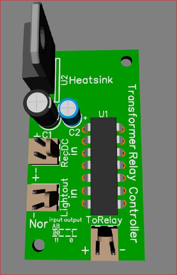
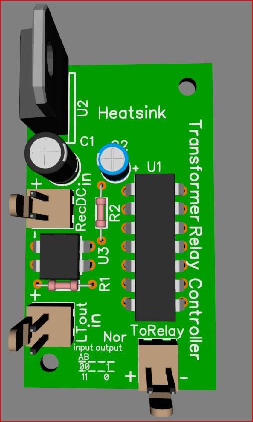
I just finished the Transformer relay controller using a Logic Nor gate. since the system is 24 volts run with solar and batteries as the main and using AC as backup i needed a way to turn the AC to DC 24 volt transformer on when the light out function of the charge controller's LVT kicked off the power from the batteries

 you see the rec in is rectified AC from the panel to a step down transformer that supplies 10 volt @ 250 milliamp to this board at all times. the light out in is from the light out of the charge controller that sends stepped down 5 volts to both input A and input B causing the output to go low. when the light out from the charge controller is cut off from LVT the output of the NOR gate goes high and that controls the input of the relay and the AC to 24 volt transformer to the system. the relay is a zero crossing type at 25 amp so it will be fine at 2.5 amp.

the voltage regulator on the board takes the rectifies 10 volt AC to 5 volts for the chip to operate. with this board i can use the solar and batteries as main and use AC from the house as back up when ever the power of the batteries get to low.

Please tell me what you think. should i go with it having two 5 volt supplies to this chip and it's inputs or should i use optical isolation and use the 5 volts on the board.


Regards,

Marathonman

  • Liked by
  • Chris
Marathonman posted this 03 September 2018

I decided to optically isolate the two supplies from one another to avoid any problems so i added that to the board. with the addition of the resistors i now can control the amount of current going to the isolation at 3 ma and 20 ma to input A and B of the Nor chip. this board will now turn the AC transformer on at zero crossing when the LVT on the charge controller cuts off giving me continuous supply to the green house system. this transition from solar to house AC is in the 10 millisecond range.

i paralleled the four circuits of the Nor chip for enough current to the zero crossing relay at 5 volts which is plenty of voltage as the relay has a 3 volt thresh hold. in the two systems i built i used a regular relay and the power was a bit spiky but it works. when i get this board in i will change out the regular relay and install the zero crossing relay and this controller board for a smoother operation.

Regards,

Marathonman

  • Liked by
  • Chris
We're Light Years Ahead!
Members Online:

No one online at the moment


What is a Scalar:

In physics, scalars are physical quantities that are unaffected by changes to a vector space basis. Scalars are often accompanied by units of measurement, as in "10 cm". Examples of scalar quantities are mass, distance, charge, volume, time, speed, and the magnitude of physical vectors in general.

You need to forget the Non-Sense that some spout with out knowing the actual Definition of the word Scalar! Some people talk absolute Bull Sh*t!

The pressure P in the formula P = pgh, pgh is a scalar that tells you the amount of this squashing force per unit area in a fluid.

A Scalar, having both direction and magnitude, can be anything! The Magnetic Field, a Charge moving, yet some Numb Nuts think it means Magic Science!

Message from God:

Hello my children. This is Yahweh, the one true Lord. You have found creation's secret. Now share it peacefully with the world.

Ref: Message from God written inside the Human Genome

God be in my head, and in my thinking.

God be in my eyes, and in my looking.

God be in my mouth, and in my speaking.

Oh, God be in my heart, and in my understanding.

Your Support:

More than anything else, your contributions to this forum are most important! We are trying to actively get all visitors involved, but we do only have a few main contributors, which are very much appreciated! If you would like to see more pages with more detailed experiments and answers, perhaps a contribution of another type maybe possible:

PayPal De-Platformed me!

They REFUSE to tell me why!

We now use Wise!

Donate
Use E-Mail: Chris at aboveunity.com

The content I am sharing is not only unique, but is changing the world as we know it! Please Support Us!

Thank You So Much!

Weeks High Earners:
The great Nikola Tesla:

Ere many generations pass, our machinery will be driven by a power obtainable at any point of the universe. This idea is not novel. Men have been led to it long ago by instinct or reason. It has been expressed in many ways, and in many places, in the history of old and new. We find it in the delightful myth of Antheus, who drives power from the earth; we find it among the subtle speculations of one of your splendid mathematicians, and in many hints and statements of thinkers of the present time. Throughout space there is energy. Is this energy static or kinetic? If static, our hopes are in vain; if kinetic - and this we know it is for certain - then it is a mere question of time when men will succeed in attaching their machinery to the very wheelwork of nature.

Experiments With Alternate Currents Of High Potential And High Frequency (February 1892).

Close