

Hello All ,
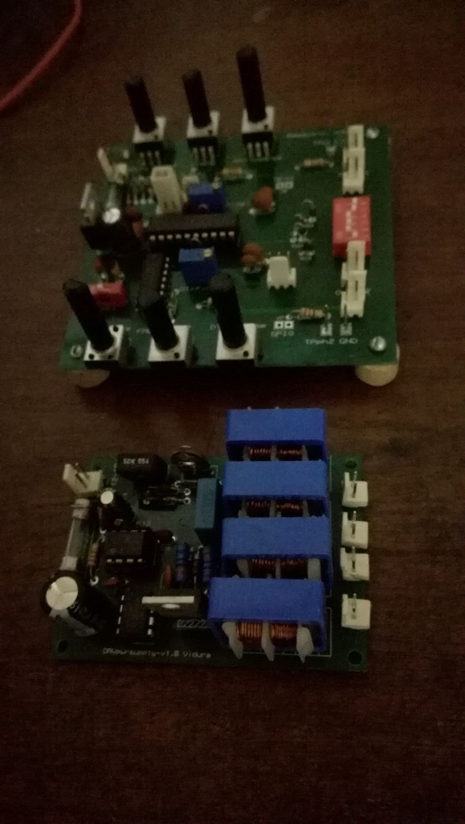
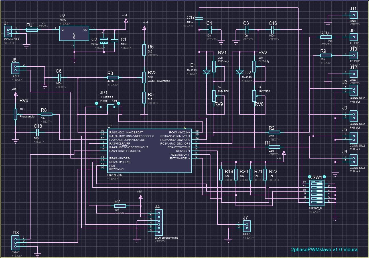
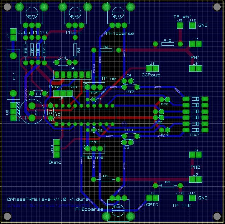
In this thread I will present tool which is designed especially for researching and developing many devices threated here on the forum. It consists of three different modules(for the moment), and is very flexible. Many different topologies of switching can be easily assembled by combining the modules in different ways and with different setups and configurations. The signal source is a two phase PWM module with combined analogue and digital features. It is based on an enhanced 8bit MC, the PIC16F785 with specific peripherals, like a dual phase PWM module and two hi speed comparators, which are used for analogue duty cycle adjustment with infinite resolution. To overcome the limited period resolution typical for digital PWM devices, an adjustable external oscillator is used to clock the MC, which in combination with the pre-scaler allow an infinite period resolution over a wide range of frequencies as well. The second module is the switchboard, which is designed as single floating switch, which allows to assemble simple Hi or Lo side pulsing, half bridge or full bridge topology, or floating coil shorting as well as multiple other configurations as required.
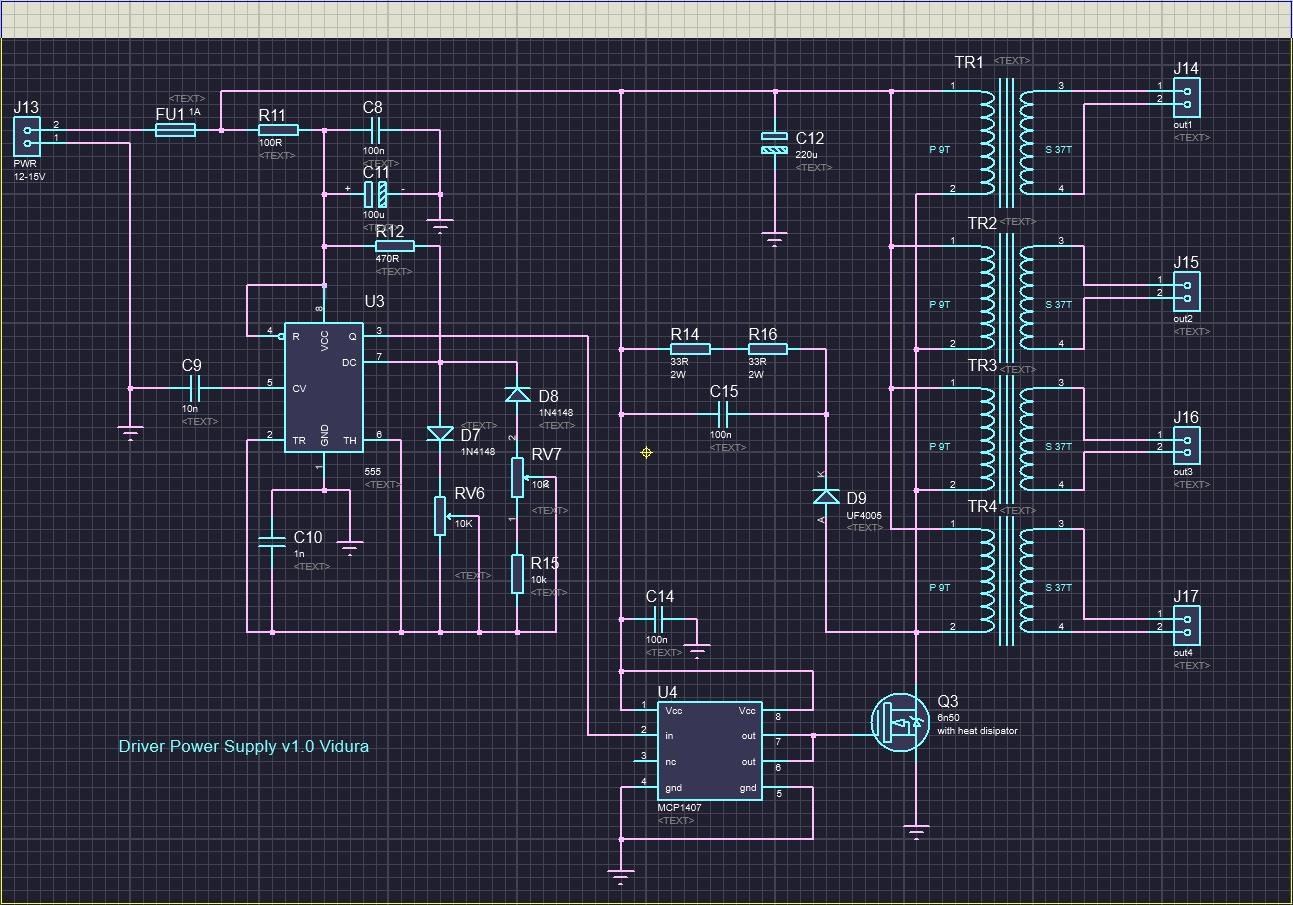
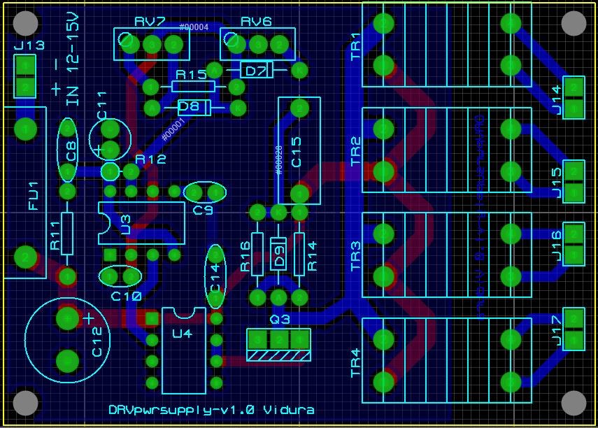
The third module is the floating driver power supply, which provides a galvanically isolated supply for various switching drivers. In the thread we will discuss different solutions for specific applications. Schematics , images and videos on the development will be released as well as firmware and software solutions for specific requirements.
Developing a modular switching tool for Research
- 4.8K Views
- Last Post 24 October 2021
- Liked by
-
-

-

-

- and 8 others

Hello All,
Here I will share a design that has been developed to substitute electromechanical switches with equivalent semiconductor devices.
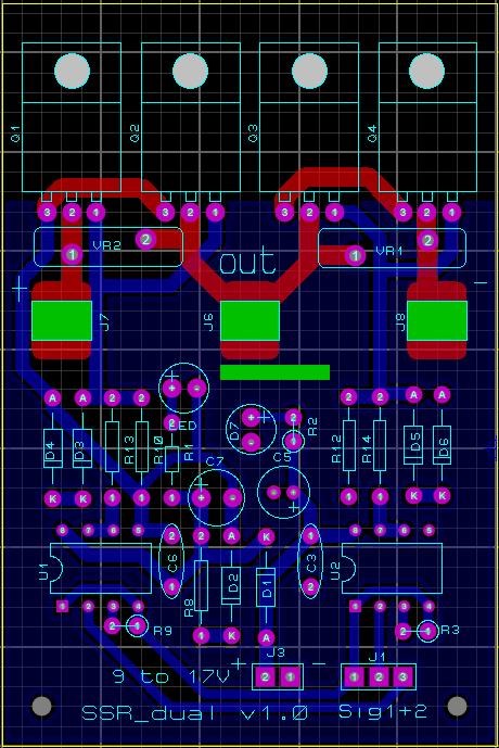
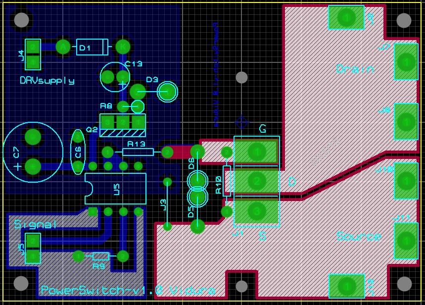
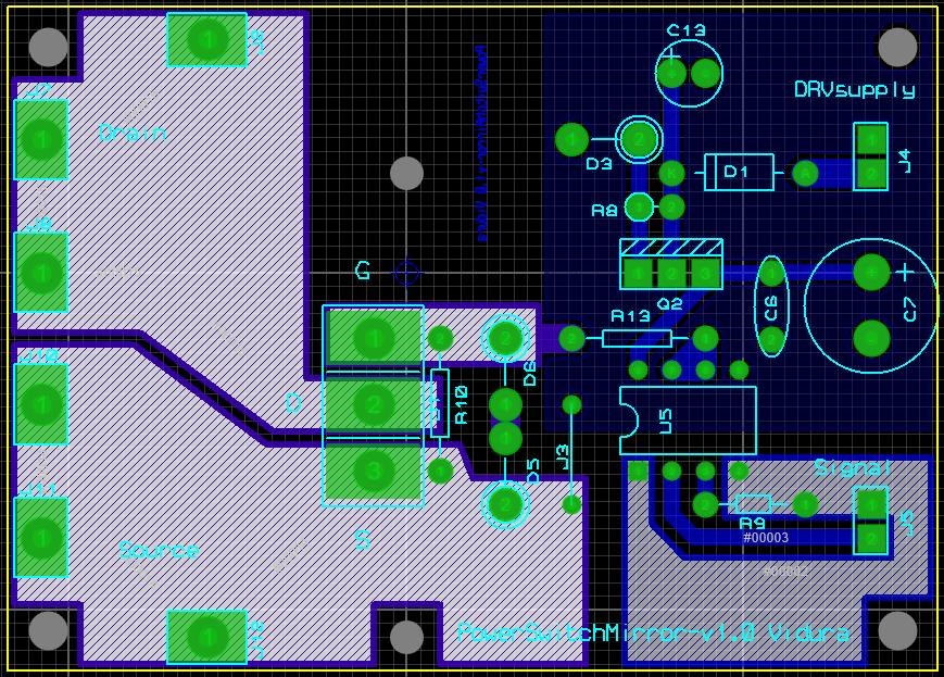
Solid state relay half bridge:
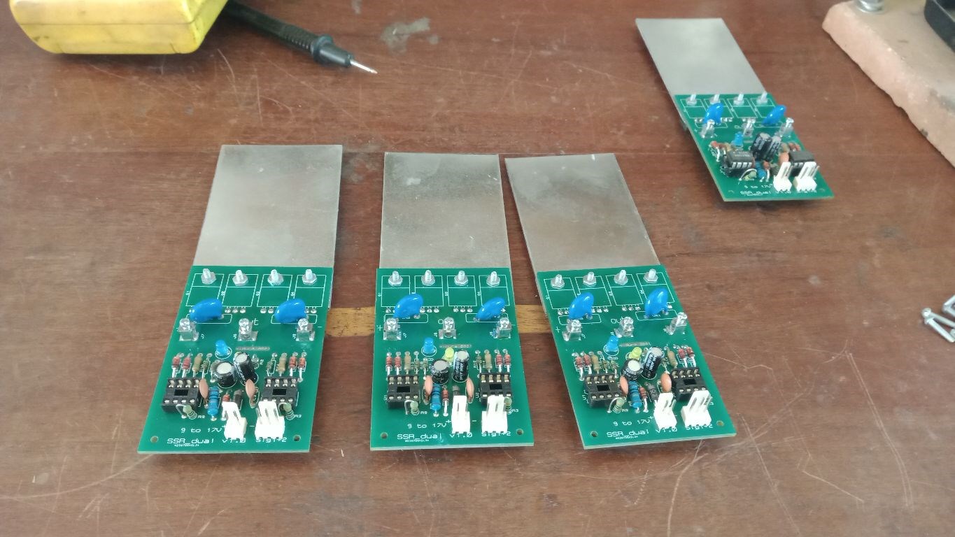
It could be especially useful for devices like the Tesla switch, or solid state versions of Figueras generator or similar devices, where likely a specific property of mechanical switches is required: conductivity in two directions in on state, and blocking in two directions in off state. The design that I will show you is built as a half bridge module, two units can resemble a H bride. It uses four mosfet(TO220) per module, two pairs connected back to back. A driver supply source oof 12-17 volts is required, the Hi side driver works in bootstrap operation up to 400v, selecting appropriated components(mosfet, bootstrap diode). The Low side switch can be used alone, but the high side switch will only work when the low side has a minimum duty cycle of 5% approximately. The schematic and layout below:
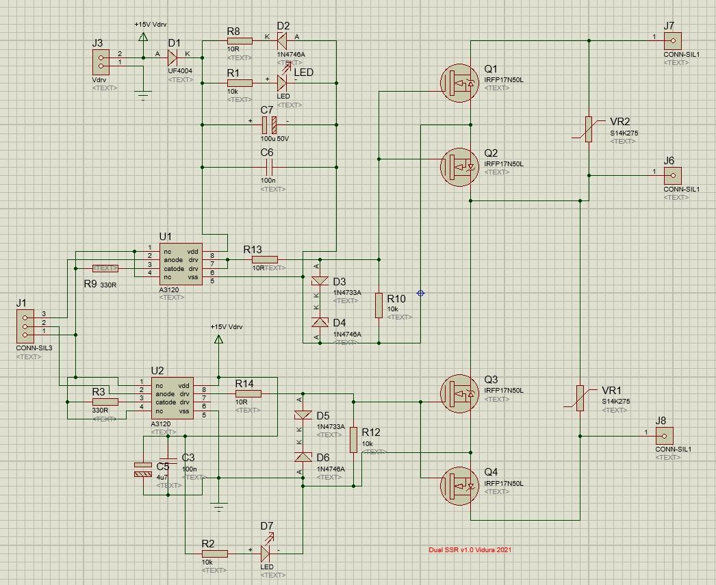
Note : For low voltage applications change the MOSFETs for the required range, and substitute the varistors for protective components matching the properties of the switches, for example TVS, GDTs.
R1,R2 can be 4k7 for better brightness of the led indicators. D1 is the bootstrap diode, and has to withstand the maximal bus voltage.
Note the mounting position of the MOSFETS pin1=gate
best wishes Vidura.
- Liked by
-
-
-

-
- and 2 others


Hello All.
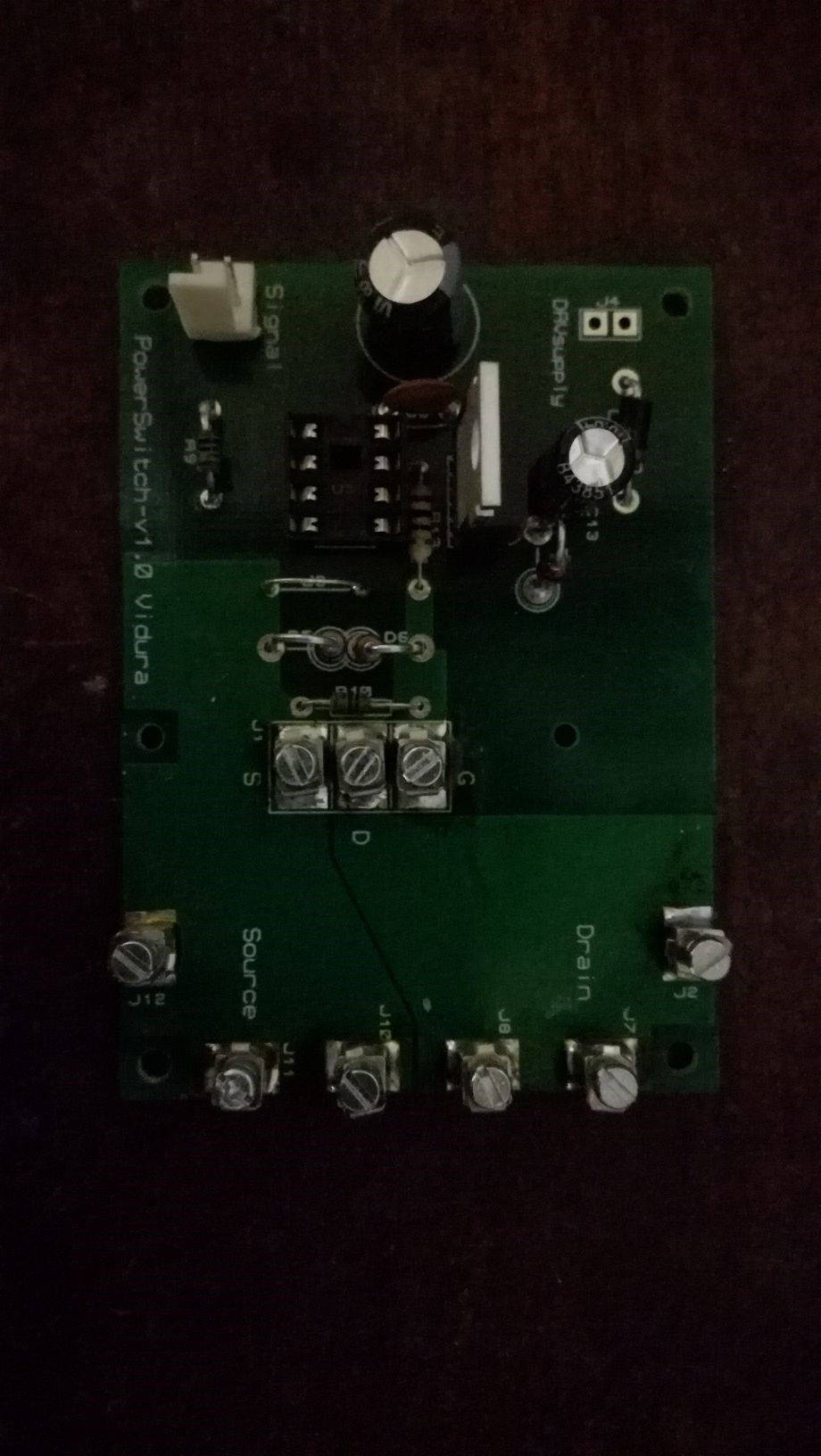
As there are several new members starting to make experiments, I will post the files for a simple modular Low side switch board. It is not isolated, indented for simple low side switching applications, and has the same features of easy change of mosfet and driver IC, gate protection and additional connectors to place TVS or MOV as overvoltage protection. The driver can be powered from a 12v battery , a PS or similar source and the MCP1407 driver can be fed with most signal sources as SG, Arduino, PWM generators, or custom made circuits. It is open source of course, the production file is attached below. A BOM will be added later. Anyone can order this boards for a few$ from a PCB manufacturer.
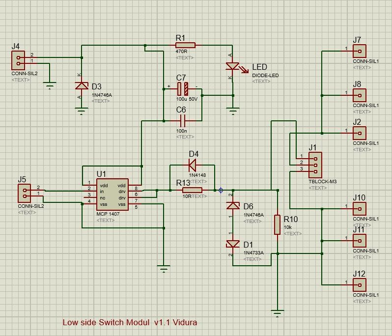
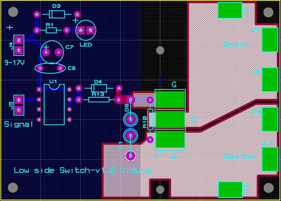
Hopefully it will be useful for some.
Vidura
- Liked by
-
-
-

Hey Ourbobby, Yes I still have PCBs. As there is not a lot of demands lately, I will give you the bare bone boards for a basic switching tool kit as a gift. Just contact me by PM, we will arrange details. Wish you a fast recovery from your health issues. Vidura
- Liked by
-
-

-

-

Hi Vidura,
I don't suppose you had any of your circuit boards left to make of your power supply?
Regards
ourbobby
- Liked by
-
-
-
-
Hello Friends.
You may have noticed that I didn't post much lately. This is due to lack of time, as I have been very busy the last two month. Anyway I'm always following the activity on the forum. So I will take the oportunity to give an update on this thread. Altough I have considered the switching tool developement as concluded, I found that there are still some things to make better, and also very important to adapt it the best way to the requirements of researchers-that means all of You.
So in first place , there have been some requests for empty PCB boards. If anyone would like to purchase some boards, for assambling it yourself please contact me by PM. It makes sense if you have the skills to assamble, as the shippment costs are less , and in many locations the components are easyer to find than here in Argentina. The PWM board will be shipped with a preprogrammed microcontroller.
Another idea that I will consider is to develope a simpler version of a PWM or maybe combined with a driver supply unit, something easyer to get started for beginners.
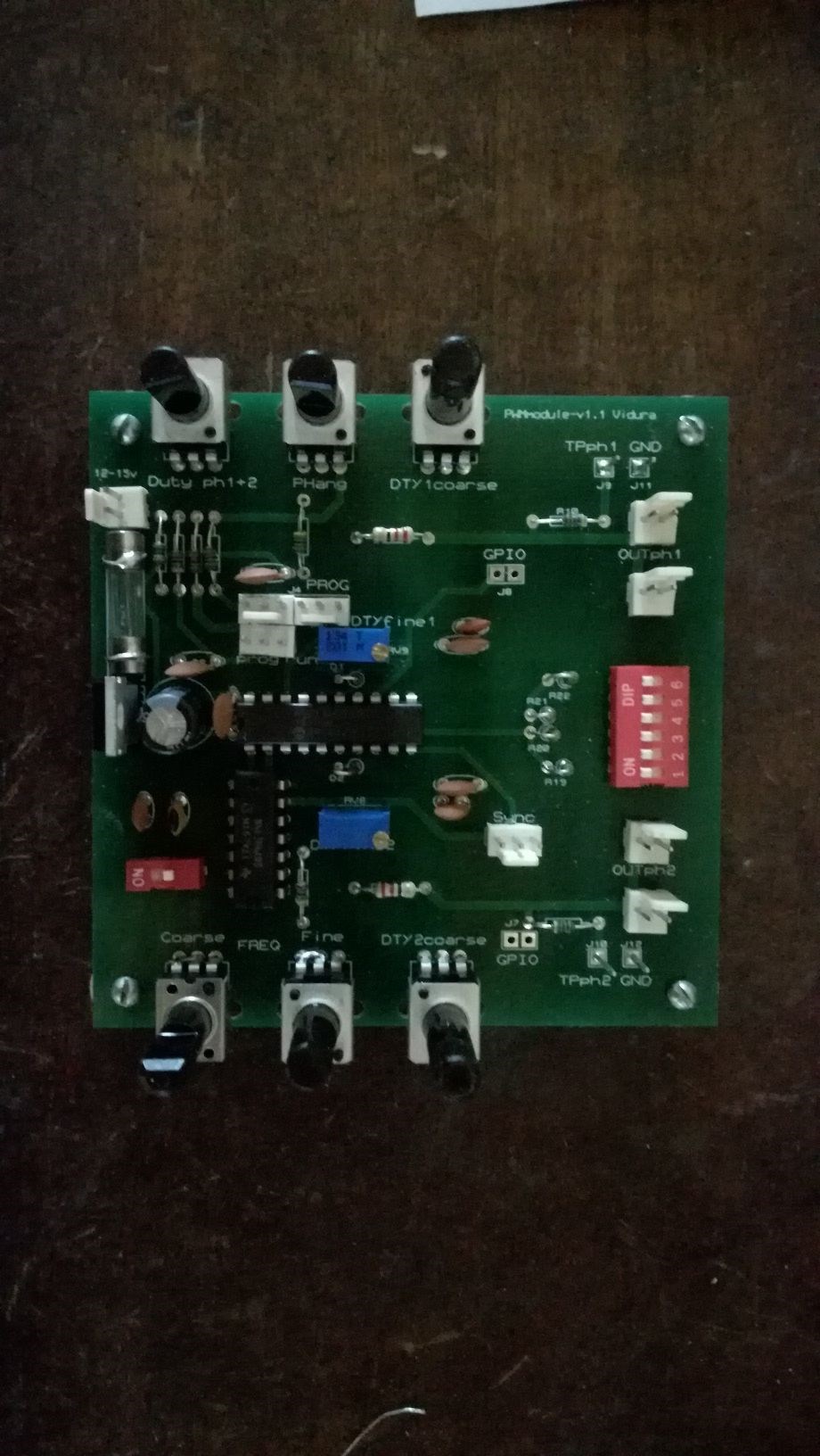
Regarding the latest version ,the PWM master module v1.3 I have already recived the PCBs , but I have planned to add a feature in the firmware to be able to generate pulstrains(gated oscillator). Also i added an led indicator for 50% dutycycle in the complementary output mode, to make the adjustment for half or fullbridges easyer.
I think that by next month I will have some more time to dedicate to this project.
Regards Vidura
- Liked by
-
-

-

-
- and 5 others
Hello All,
Now with the new version of the PWM module , which came out really nice, the development will be considered concluded. there might come some minor improvements still on some of the modules , but now we can already say that they are fully operative with excellent performance. For this reason I have removed the donation bottom from this thread, and put it to the thread " Towards a more complete understanding of EM" where some components and equipment's would be very helpful.
Here a short presentation of the new PWM module:
What I wanted to add is that I have still a few PCBs from the first version, which will be adapted to the new oscillator, and they will be available with a discount, due to the small details in the physical presentation, but fully operational like the one shown in the video. The new PCBs have been shipped already, but this might take some time due to the Argentine Post. My metglass core is now in transit since beginning of September, and still no notification from customs .
.
Regards Vidura
- Liked by
-
-
-
Hey Chris, You are right, it is a phase locked loop circuit of course, sorry for the mistake. Vidura
- Liked by
-
-
-

-

Hey Vidura,
I wonder, do you mean a PLL, Phase Locked Loop? instead of a PPL?
Chris
- Liked by
-
-

-
-
A few days ago I have received some 74HC4046AE devices, these are cmos PPL ICs. In first place I had planned to build the self tuning oscillator , which YoElMiCrO have shared the schematic. So I thought to give it a try also using it as a clock oscillator for the PWM modules, as it have a voltage controlled oscillator which is capable to output up to almost 20 Mhz. So I have built an oscillator on a proto-PCB and first connected extern to the PWM boart to provide the clock signal for the PIC16 F785. After finding the correct values for components it performed really excellent, Now I'm really happy with the performance and the missing sensibility for the frequency adjustment is finally achived. With a little bit of artwork I can modify the remaining PCBs, until I can order a new Batch for the new version, this can take some time in my place, My metglass core is on jorney till more than 50 days now ,and I have still no notice from customs to do the clearance.
Regards VIDURA.
- Liked by
-
-
-
-

- and 2 others
Hello All,
A few lines regarding the PWM master module. I wanted you to know that the development still continues, I am using and at the same time testing the tool kit. Although it is operational and very helpful, I still found some things to improve. Personally I prefer it before the SG for most experiments, specially the free running mode with constant pulsduration is very helpful, also the complementary output mode for driving half or full bridge configurations. I found some details to improove, the most important is that the frequency adjustment with the potentiometers should be more sensible in the upper frequency range. I am working on this, a new version is in development, it will likely use a different system clock generator with better adjustment sensibility. also a sweep mode is considered to be added. Of course those who already have purchased a unit of the first version will have the possibility to upgrade to the new version with preference at a minimal cost of materials only. I want to give special thank's to YoElMiCrO , who is helping me with professional technical advice.
Regards VIDURA.
- Liked by
-
-
-
-
- and 1 others
Hey getreal156,
For the moment I do not publish in eBay, as the economical situation is very unstable and difficult, but you want to place an order just PM me and tell me in which parts you are interested, so I can send an estimate and a paypal link. I have still materials for assembling some units. Thank's VIDURA.
- Liked by
-
-
-
-

Hello Mimo, This looks good, it is in the recommended operation range 10-16mA, so you can use your SG with this voltage. Vidura
- Liked by
-
-
-

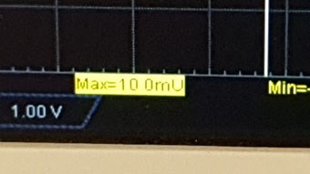
Hello Vidura,
here is a better picture of the measurements. The division is effectively on 10.0mv.
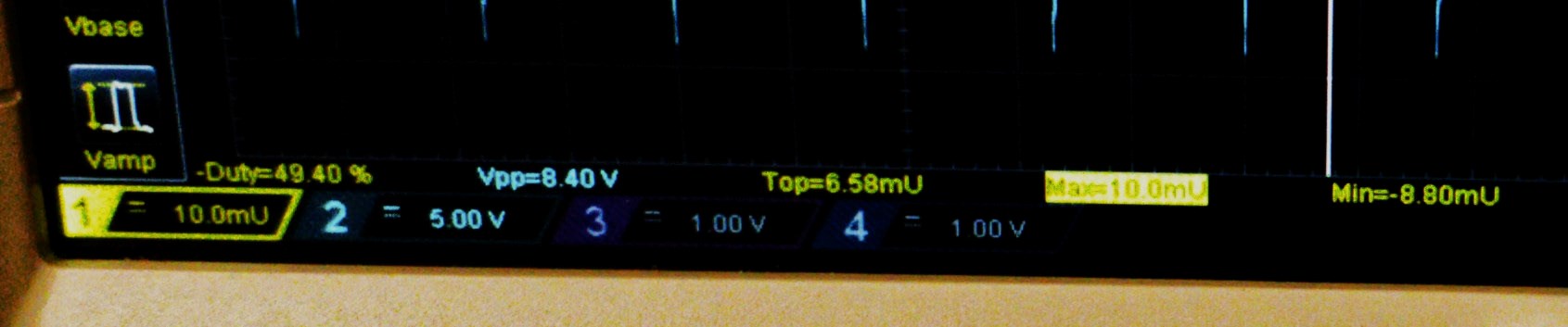
Mimo
- Liked by
-
-
-
Hello Mimo, If I see correctly the scope is on 10mv /division so it would be around 15 mv , which is perfect. Your SG seems to be better quality than mine. Thanks for sharing. Vidura
- Liked by
-
-
-
-
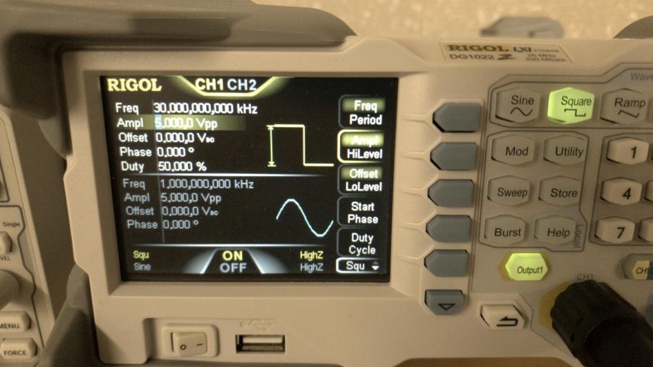
Hello Vidura,
and to all.
This is my first post, but I have been with you since the forum was created. I am located in France.
I did the test with my SG Rigol DG1022 with Ampl 5 volts.
I get a VMax of 10 mv, with the resistance of 1 Ohm that I received with the modules.
Note : VTop: 6,58mV and VMin: 8,80mV
It does not seem necessary to increase the Ampl of the SG, is'nt it.
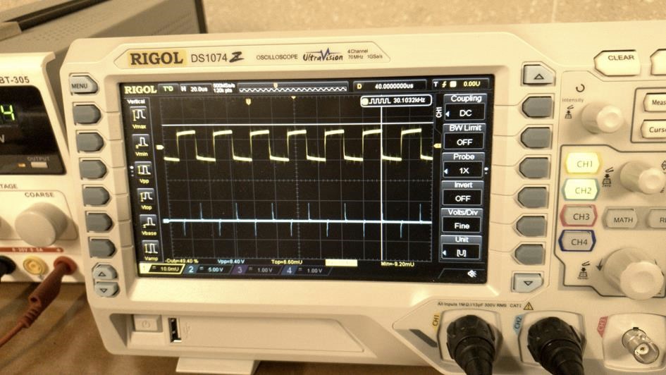
Mimo
- Liked by
-
-
-
-
- and 2 others
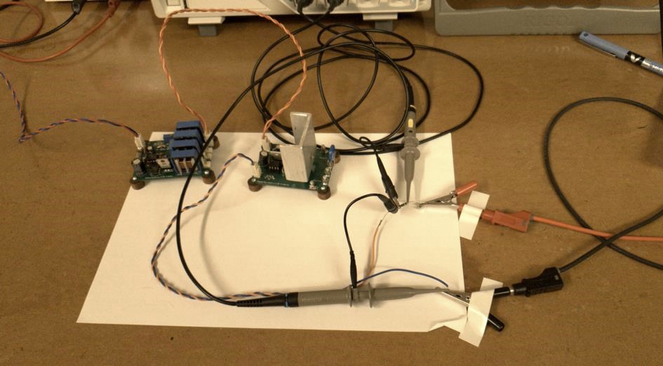
Every now and then I find some odd things going on: I was checking the signal parameters when I drive the Power Switch Modules with the Signal Generator, and compared with the signals from the PWM module. So I measured the voltage and current of the signal fed into the input of the Driver IC. With the PWM Module it was strait forwards, 4.5 V as expected for a 5V processor, and an emitter current set to 10 mA, everything o k. But when I connected the module to the SG. it hardly reached the threshold current of 3mA for the Driver, although the output was set to the same voltage of 5V and controlled with the scope it was 5V !! To get the correct current for the driver I had to rise the voltage of the SG to 10V. The only explication I have is that the signal of the SG is composed digitally at much higher frequencies(above the capabilities of my scope), and that this high frequency components have a major influence on the impedance of the circuit. As I'm not sure if all SGs perform the same way with this type of Drivers, or if it might be a general property of Digital SGs, I would ask those who have ordered Power Switch Modules to check this with a 1Ohm resistor in series with the signal connection and measure with the scope. The voltage drop across the 1 Ohm resistor should be 10-15mV for good switching performance, In my case I need to set the SG output to 10-12V.
Vidura
- Liked by
-
-
-
-
Hey Vidura,
I am not a business person either! We just have to do what we have to do 
Good luck in what path you opt for and don't forget to let me know and I will put a link on the Side Menu.
Chris
- Liked by
-
-
-
Hey Chris,
as I'm not a experienced businessman I was studding a bit the requirements for this , it seems to be possible with Ebay, although in latinamerica a similar onlinemarket exists called MercadoLibre, but for international trading Ebay would be preferred. I will you keep updated
vidura
- Liked by
-
-
-

Nice fighter, - but i fear you may actually be the second. #winks
btw my cores have been manufactured, i just received confirmation email, - they will arrive in 1 week.
& at 6% of the price of the hitachi metglas. - and so far as i can tell, very similar specs.
- Liked by
-
-
-
-

I'm the happy buyer of the first set, I bought 4 PowerSwitch modules and 1 PowerDriverSupply, I intend to command the switches with my signal generator.
Guys, I consider this a must-have tool for researching and experimenting with any type of OU device.
My hat off to Vidura for his advanced knowledge in electronics and for the effort made for designing, testing and making it available to our community. It's a lot of knowledge and work incorporated in these devices...
- Liked by
-
-
-
Hey Vidura,
How are you going to manage sales? Will you put them on eBay?
If eBay let me know and I will post a link on the navigation pane on the side!
Chris
- Liked by
-
-
A short update, the Switching tool is now released for ordering, the issue of sensibility on the coarse frequency adjustment is quite good solved with a multiturn potentiometer. Here some images of ta basic Full bridge set:
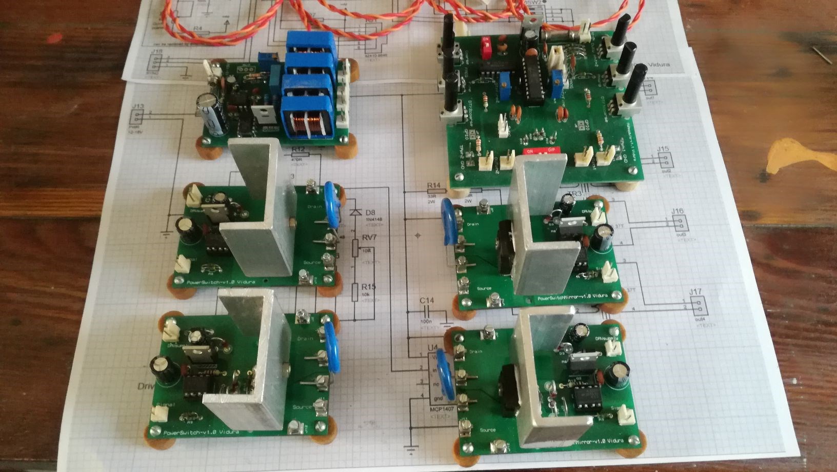
The slave module I am building some units with the new PCB's, and what's still pending is the users guide(work on progress) and tutorial videos will follow as well.
I want to give thanks again for those who have supported the development with donations.
Regards VIDURA.
- Liked by
-
-
-

-
- and 3 others
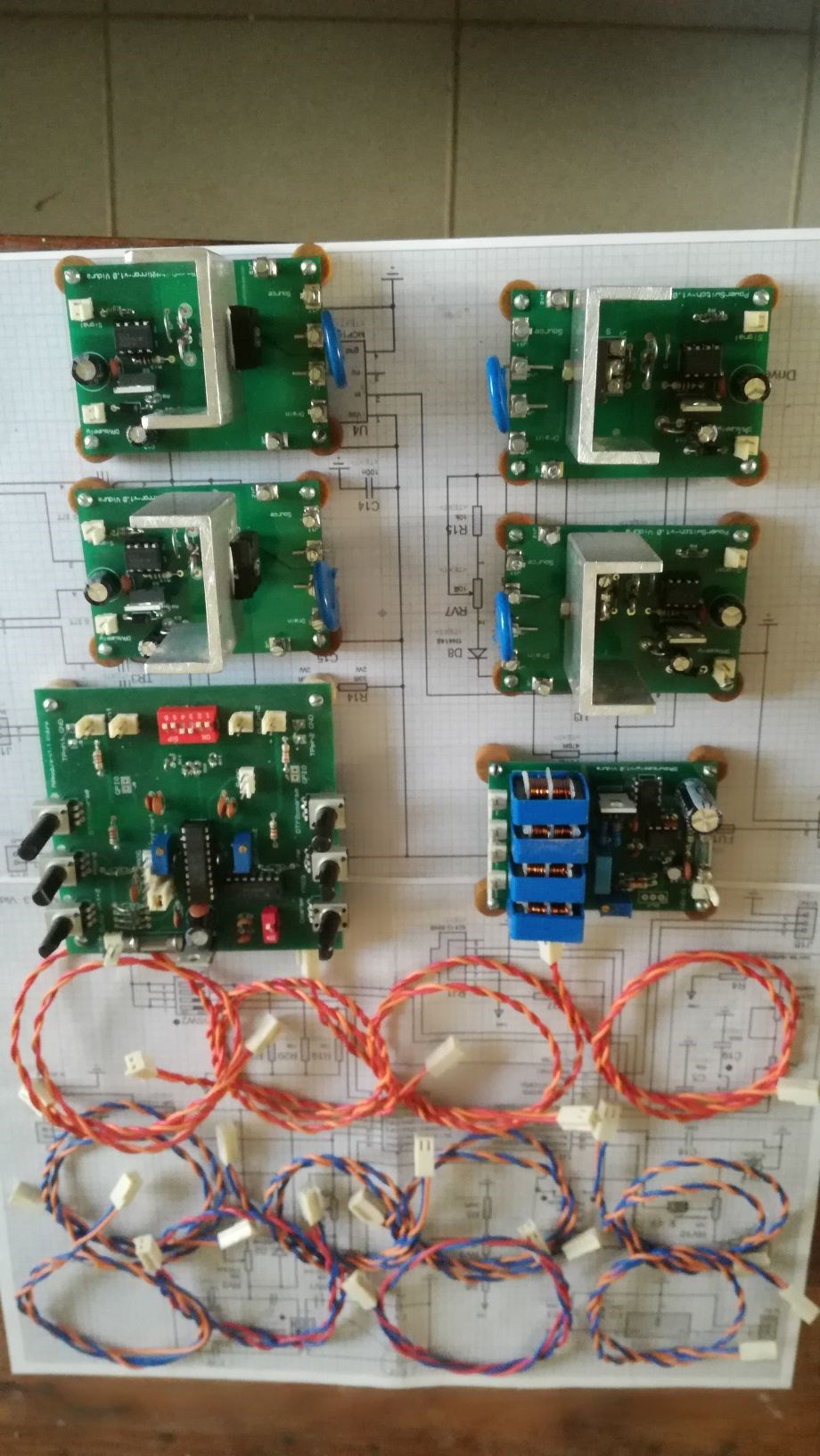
Hello All,
Although the two phase PWM module is still not perfect it turned out quite usable, also the interference from the driver power supply is resolved and the switching modules are performing excellent, floating, very versatile and clean switching performance. So I felt that it is time to release the tool for order , with the PWM module as beta version still. I will make a short video where I will show the weak point that is still on the design, regarding the sensibility of the frequency adjustment. Today I began mounting some switching boards and driver power supplies, as these parts can be perfectly used with a signal generators or other signal source , I thought that it could be helpful for many experiments already, so I'll release this modules for sale. Anyone who's interested just PM me please.
The Switching modules will be supplied with IGBT's H25R1203, which are revers conducting, 1200V and 25A rated ,really tough devices from Infineon, and with the HCPL3120 Optoisolated Gate Driver.
The Switch is easily exchangable with screwconnectors.
Some pic's of assembly progress:
Regards Vidura.
- Liked by
-
-
-
-
- and 1 others

Hello All.
A short update, I was working on the project with the new PCB's and the progress is good. The PWM board works satisfactory, and I was fixing the interference issue of the switching powersupply, changing the transformers and frequency and duty I got a much smoother output , the disturbing transient spike has disappeared and the efficiency increased, the mosfet runs cold now without heatsink. Finally is was not necessary to redesign the module, the PCB's can be used as they are. For those who want to build a unit of the PWM module I want to notify that there is a error in the schematic still, which dont allow in-circuit programming of the MC. I will change the schematic for a corrected version soon.
Regards Vidura
- Liked by
-
-
-
-
- and 2 others

Today I've assembled the first PWM module with the new PCB's. Tomorrow I will test again, how the oscillator is performing with the logarithmic potentiometers, and continue with the other modules for a final design check.
Vidura
- Liked by
-
-
-
-
Hi Friends,
Back at home, with the machined PCB's and some more components ! I have a lot of work to recover at home and business also, but hopefully will be able soon to progress with this project (and others). 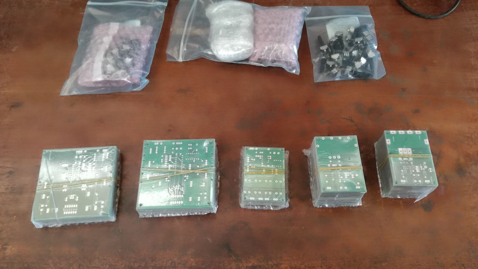
Vidura
- Liked by
-
-
-
-
- and 1 others
Muchas gracias por ofrecerme tu ayuda, me di cuenta que tienes experiencia en electrónica. Voy a hacer algunas consultas para mejorar los diseños cuando vuelvo del viaje. Vidura.
- Liked by
-
-
-

Hola Vidura, si puedo ayudarte en algo me dices. Desde ya gracias a todos.
- Liked by
-
-
-
Hey Chris and All Sorry for not posting anything lately, I m on journey, far from the bench. Got the PCB board s from China, and placing some orders for components. The switching modules performed very well, the PWM module had some difficulty in the frequency adjustment at the very upper range, which I will try to resolve using logarithmic potentiometers when I m back at my workshop, or otherwise return to the previous oscillator version, which had a more linear behaviour in frequency adjustment. The driver power supply produces eventually some interference in the PWM at high frequencies, so I think I'll redesign this module, with filtered DC output current. By next month I'll be back on work, Regards Vidura.
- Liked by
-
-
-
-
Hey Vidura,
Thought I'd check in on how you're going on this important project.
Chris
- Liked by
-
-
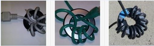
Hey Jagau,
I have tried to eliminate the interference with some ferrite toroides that I had at hand from common mode chokes, it did not result as expected, maybe the special ones from Palomar would do the job, but anyway it would be complicated and timeconsuming to get them. Finally I could filter it out by connecting a 47nf cap in parallel to the primaries of the transformers, it has improved a lot, the signal is almost perfectly clean now. Anyway I decided to do a new version of the driver supply, change from flyback type to sinewave transformers , much less noisy and less power consumption at no load condition. Also I will add four more outputs for an additional H-bridge on the slave module, if needed.
Vidura
- Liked by
-
-
-
-

yes vidura
Some time ago I was looking for a solution and this page had given me a helping hand
https://palomar-engineers.com/rfi-kits/am-broadcast-rfi-kits/
There is even a small calculation to know how often we want to eliminate
Jagau
- Liked by
-
-
-
Hey Jagau,
yes this could work, i'll give it a try, as it is simple to add . The flyback transformer with short duty cycle is a bit noisy , maybe placing this kind of filter on the output of the supply will solve it without modification of the circuit.
- Liked by
-
-
-
Hi Vidura
Maybe you will have to use filters to reduce electromagnetic interference like these
in order to reduce the negative EMI / RFI effects?
Jagau
- Liked by
-
-
-
Hi all, The PCBs are ready, yesterday they have been sent for shipping. I will receive them in Europe next month, to avoid inconvenience with customs, as I have explained earlier. Meanwhile testing is going on, according the time I can invest at the moment. I still found a couple of Improvements to make, in first place the driver power supply is causing some interference in certain ranges, I will try to fix it adding filters , or otherwise change to a sinewave signal or DC output. The second issue were the connecting wires, it might be necessary to use shielded RF wires, as there are also some interferences in the signal when switching hard. Hopefully I will post some tests soon, also in other threads according to the topics, and to add some relevant information. Regards Vidura
- Liked by
-
-
-
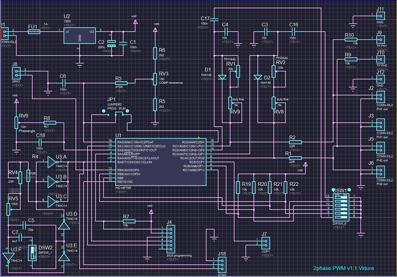
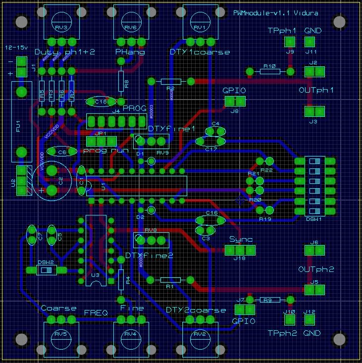
Hi all!
Today finally I concluded the production files for the Tool modules , and thanks' to the support received from donations could place order for the first batch of PCB's. I also could include the slave module and some additional Power switch boards, so more complete toolsets will be offered. Here I will post the updated schematics and layouts of the modules.
Regarding the dedicated oscillator this is the basic circuit:
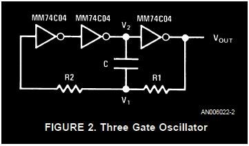
when testing I found that R2 had virtually no influence on the frequency, only distorted the signal a little at high frequencies, so I modified the circuit , the result you can see in the schematic of the 2phasePWM-v1.1 It was possible to extend the range from 23hz up to 360khz, the adjustment at the highest range becomes a little less sensible, but this should improve with the implementation of log potentiometers.
The designs can be used for non commercial implementation.
Regards Vidura.
- Liked by
-
-
-
-
- and 1 others
Yes you are right, the oscillator is used as a common time base for various MC's . As it is a signal im most cases it can be connected in parallel without inconvenience if wiring and conductors are chosen accordingly. There is a design in the Figurea thread where various decade counters are connected to a common clock source that way for a solid state circuit.
Vidura
- Liked by
-
-
-

I knew you would same a heck of a lot of money with them but 500 bucks WOW that is a lot of savings.
can you not find a duel output oscillator that outputs complementary and in phase outputs. or would this be the wrong application.
Marathonman
- Liked by
-
-
-
Hi All ,
some news here, when i got the estimate from a local PCB supplier for ten kits(60 boards ) was about 550$ !! in PCB way it's 50$ shipping included. I had already placed the order, still not payed, butI was not at all satisfied with the synchronization of the slave board, as the main PWM board with the external RC oscillator outputs a clock signal divided /4(system clock) for the slave board. So in the upper frequency range the slave board duty cycle was truncated as its clock was 4 times slower. So I looked for a suitable dedicated external oscillator, to feed the same clock frequency to both MC's. I wanted a simple reliable circuit with at least the same range then the actual version. In a application note for CMOS Schmitt-trigger I found a simple ring oscillator which performed quite good, including more extended range, only I have to get logarithmic potentiometers for the adjustment, as with the linear ones a sensible adjustment in the upper freq.range is difficult. So I cancelled the order, to upload the latest version when finished.
VIDURA.
- Liked by
-
-
-

-
Hey Vidura,
Awesome work!
If we were to take The MEG as an example, we have a very straight forward waveform to replicate, known to work, verified by several other researchers. The correct waveform:
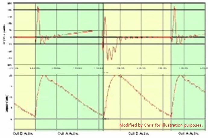
I was going to do a whole new thread on this ( Basic Facts as a Guide ) but I think you already have all that down! The input, two Short, perhaps 10% Duty Cycle Pulses. The Output Coils are bought into magnetic Resonance, where One Output Coil is Tricked into assisting the Input, and this is after the TVS Conduction, delayed Conduction. Normally of a very short duration, in the region you are adjusting for!
Vidura, I am so impressed! This is exactly what we needed! As a Community! Someone with the Electronics skills to bring a tool to the table with the flexibility to give the timing required. With only a little work, your Circuit will be able to produce the required signals to bring about Magnetic Resonance:
- Input Magnetomotive Force in the Positive Direction.
- Output Magnetomotive Force in the Negative Direction.
- Output Magnetomotive Force in the Positive Direction.
We trick one Coil into Assisting the Input Magnetomotive Force with the use of Delayed Conduction. Which is: 1 + -1 + 1 = 1.
Excellent Work Vidura!
Chris
- Liked by
-

-
.jpg?width=20&crop=0,0,20,20 "fer123")
-
-
- and 1 others
Here a short test of the first attempt of the PWM slave module, there is still a lot of work and solving issues ahead, anyway the resolution for timing between the boards is fine. The basic Idea is to use two phases of one board to drive a half- or H-bridge for the input and the second board for POC switching, eventually by a synchronous rectifier. Note that also a single main PWM board can be used for a single switch input and output with the same resolution between the two phases and that the dutycycle resolution remains constant when changing the frequency.
Vidura
- Liked by
-
-
-
-
- and 3 others
Hi all, Just some lines to keep you updated. For the moment I'm working on the production files for the first three modules PCB's,
I want to get out most possibilities from the hardware, taking in account some possible extensions or variations. I'm also evaluating possibilities to get the PCB's faster, this week I will get some estimates from local suppliers, I dont think to find a price nearly as cheap as PCB way, but if there is interest for orders in short terms it would be possible to resolve this way. Also I began to make the Slave Device , a second PWM module which runs synchronized with the main board, I had in mind some test setup's to experiment with the delayed conduction POC, testing timing in <us range. I still did not have the time to perform it, due to many difficulties in daily live, lately. I want to say Thank you to all supporting this work , and the Forum in general. Thank you so much! Ill keep you updated on the progress, more to come soon.
VIDURA.
- Liked by
-
-
-
-
- and 2 others
Hey MM I have no doubt about the service of PCBway, the problem here in Argentina is the local imposed puppets government, they work so hard to promote poverty and please the international monetary entities. The delays of delivery are not understandable, horrendous customs fees and inefficient clearance administration do the rest. Next month I'll traveling to Europe, there are better conditions for importing, so I thought to receive the materials there. Regards Vidura.
- Liked by
-
-
-
-
Just to give you a idea of how fast PCB Way is i ordered a test circuit board on 5/30, i just received a shipping manifest stating i will receive my order on 6/04 from DHL. i can not even get that kind of service here in the USA not even Osh Park.
also i had a dollar off coupon so the boards only cost me 4 dollars plus shipping @ 10 boards <100mm x <100mm and this my friends is one hell of a deal.
this is of course for the electronic version of part G.
Keep up the good work.
Regards,
Marathonman
- Liked by
-
-
-
-
The latest progress, first assembly of a H bridge setup, to test the modules under load:
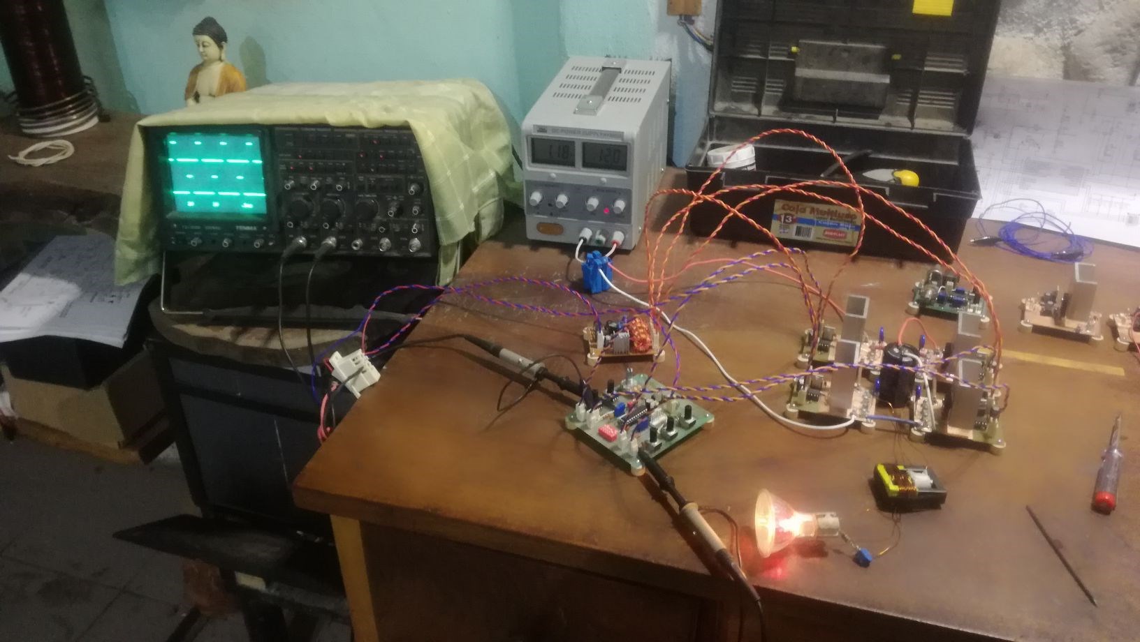
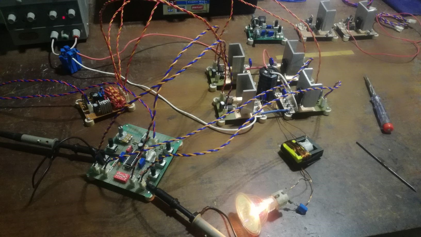
I had some minor issues still with the program code, when I activated deadtime in analogue complementary mode the processor
stopped some times, for the instance I left only the counter mode for the complementary output , which permits a 5 bit resolution for the shifting of duty cycles, which is ok for most drive requirements. The liberated dipswitch is now used to switch over one potentiometer for deadtime adjustments from 5 to 155ns. Anyway the independent mode is available with all full analogous adjustments for special applications.
Vidura
- Liked by
-
-
-
-
- and 1 others
The interactive and interchangeable modules is a very good idea.
great job vidura
Jagau
- Liked by
-
-
-
-
Hello all, here a first video explaining some features of the PWM module:
- Liked by
-
-
-
-
- and 4 others
Hey Chris,
I'm just uploading a video which should explain the basic features, it should be viewable in a few minutes.
The MC has the two phase PWM peripherical with analogous dutycycle which has two outputs, then there is a common single channel CCP digital PWM, which is unimplemented for the moment, but it can be programmed for a third channel, as it has the same system clock, it could be sincronized. For more channels- phases there can be connected additional MC's as they can be configured as Master and Slave devices via sync. connector.
Vidura
- Liked by
-
-


No one online at the moment
Past Visitors: 0 | Live Visitors: 0
3D globe widget by: Chris Sykes
In physics, scalars are physical quantities that are unaffected by changes to a vector space basis. Scalars are often accompanied by units of measurement, as in "10 cm". Examples of scalar quantities are mass, distance, charge, volume, time, speed, and the magnitude of physical vectors in general.
You need to forget the Non-Sense that some spout with out knowing the actual Definition of the word Scalar! Some people talk absolute Bull Sh*t!
The pressure P in the formula P = pgh, pgh is a scalar that tells you the amount of this squashing force per unit area in a fluid.
A Scalar, having both direction and magnitude, can be anything! The Magnetic Field, a Charge moving, yet some Numb Nuts think it means Magic Science!
Hello my children. This is Yahweh, the one true Lord. You have found creation's secret. Now share it peacefully with the world.
Ref: Message from God written inside the Human Genome
God be in my head, and in my thinking.
God be in my eyes, and in my looking.
God be in my mouth, and in my speaking.
Oh, God be in my heart, and in my understanding.
We love and trust in our Lord, Jesus Christ of Nazareth!

More than anything else, your contributions to this forum are most important! We are trying to actively get all visitors involved, but we do only have a few main contributors, which are very much appreciated! If you would like to see more pages with more detailed experiments and answers, perhaps a contribution of another type maybe possible:
They REFUSE to tell me why!
The content I am sharing is not only unique, but is changing the world as we know it! Please Support Us!
Thank You So Much!
-
Chris
440
-
Nurplex 140
-
 Plasmonic
70
Plasmonic
70
-
 FastWalker
2
FastWalker
2


Ere many generations pass, our machinery will be driven by a power obtainable at any point of the universe. This idea is not novel. Men have been led to it long ago by instinct or reason. It has been expressed in many ways, and in many places, in the history of old and new. We find it in the delightful myth of Antheus, who drives power from the earth; we find it among the subtle speculations of one of your splendid mathematicians, and in many hints and statements of thinkers of the present time. Throughout space there is energy. Is this energy static or kinetic? If static, our hopes are in vain; if kinetic - and this we know it is for certain - then it is a mere question of time when men will succeed in attaching their machinery to the very wheelwork of nature.
Experiments With Alternate Currents Of High Potential And High Frequency (February 1892).
