Ourbobby's Bucking Coil Experiments

  • Topic Is Locked
  • 3.8K Views
  • Last Post 16 January 2021
Ourbobby posted this 13 June 2020

Hello,

I am putting this message into this Bucking coils thread, not being sure where else it can go. And, especially as I am looking to understand the Floyd Sweet contribution.

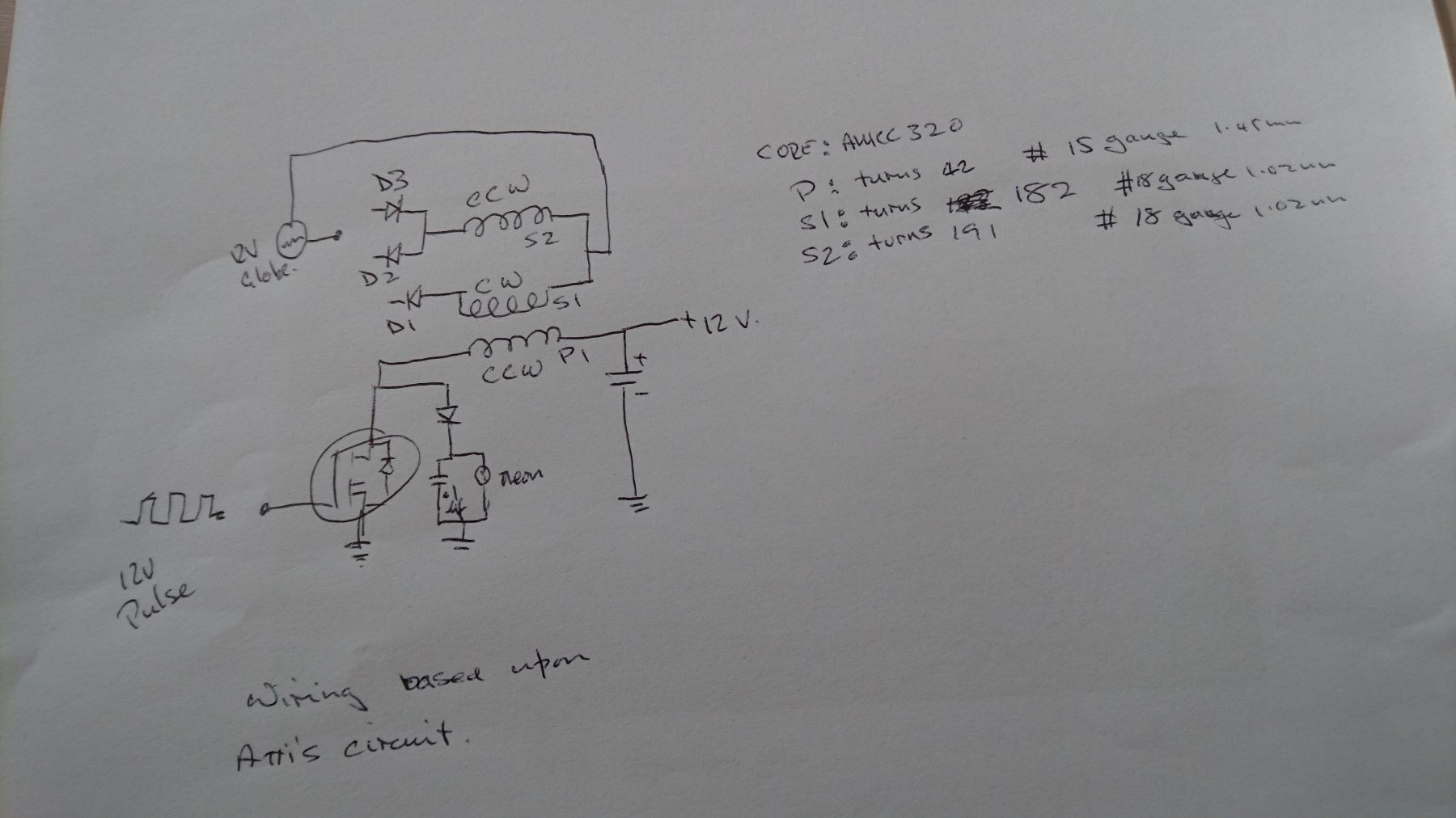
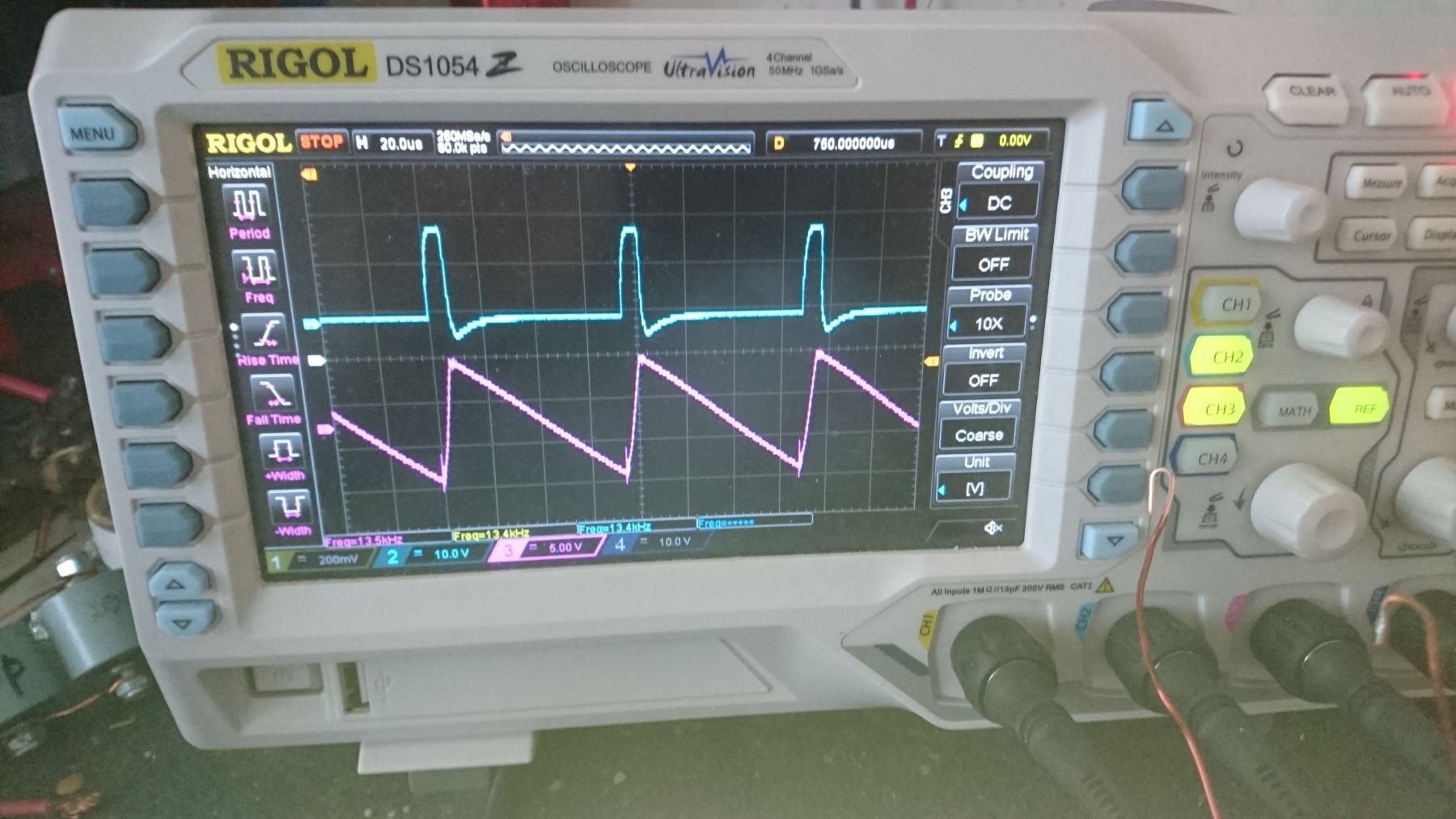
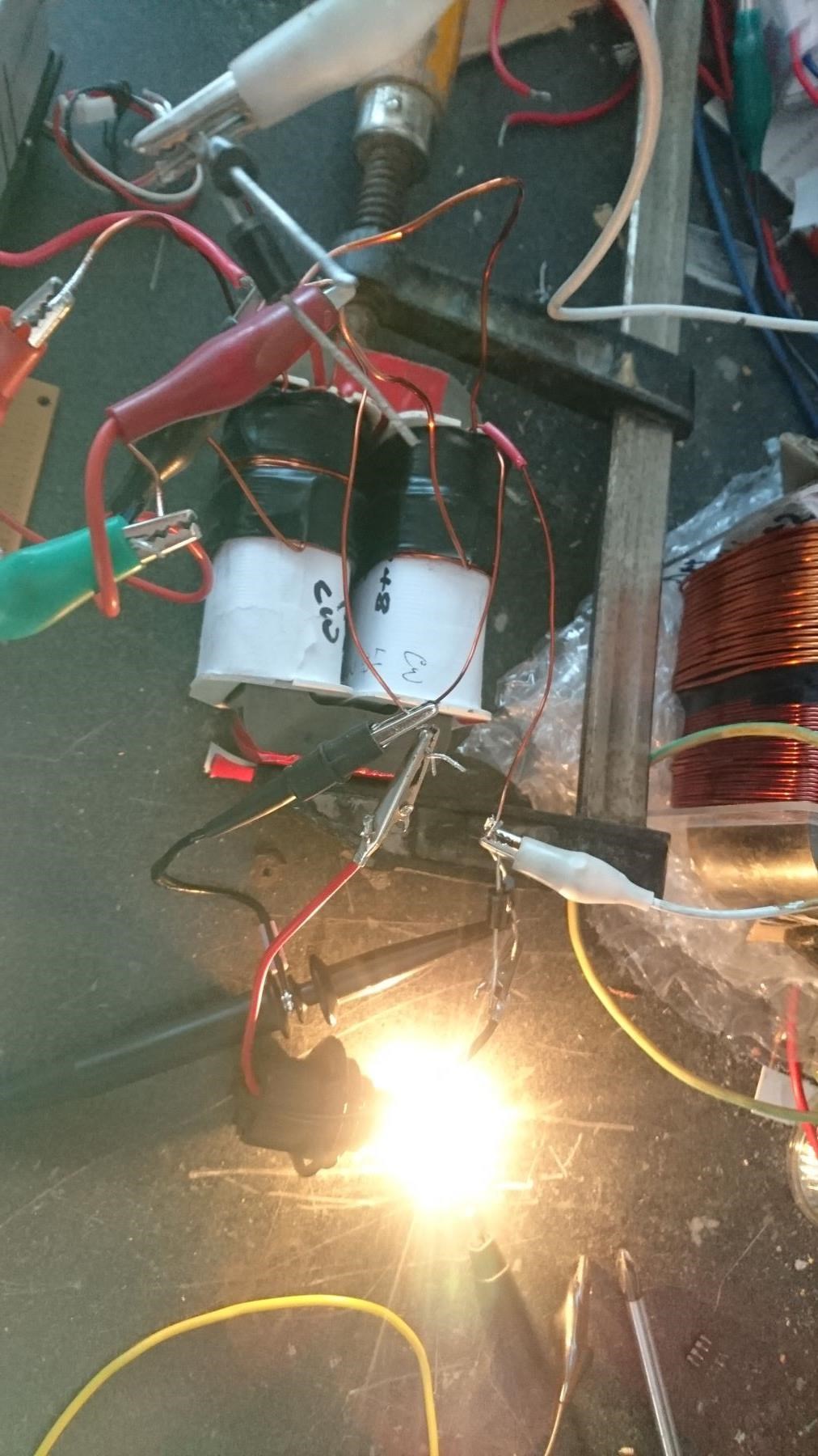
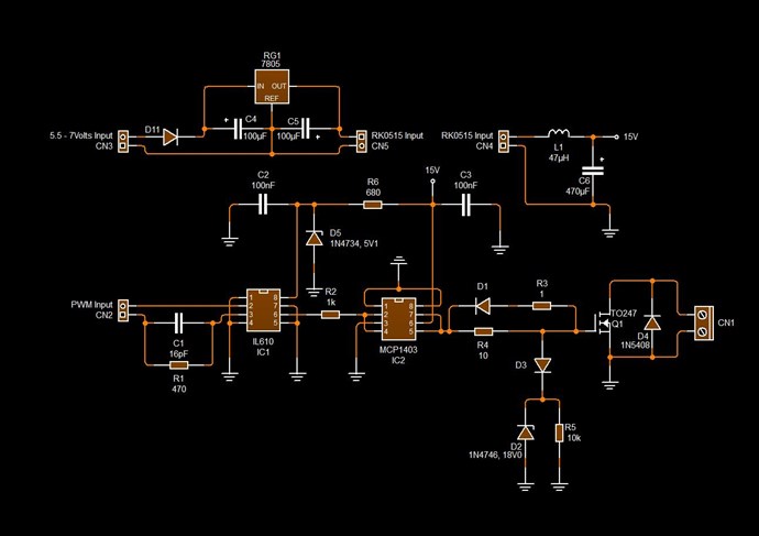
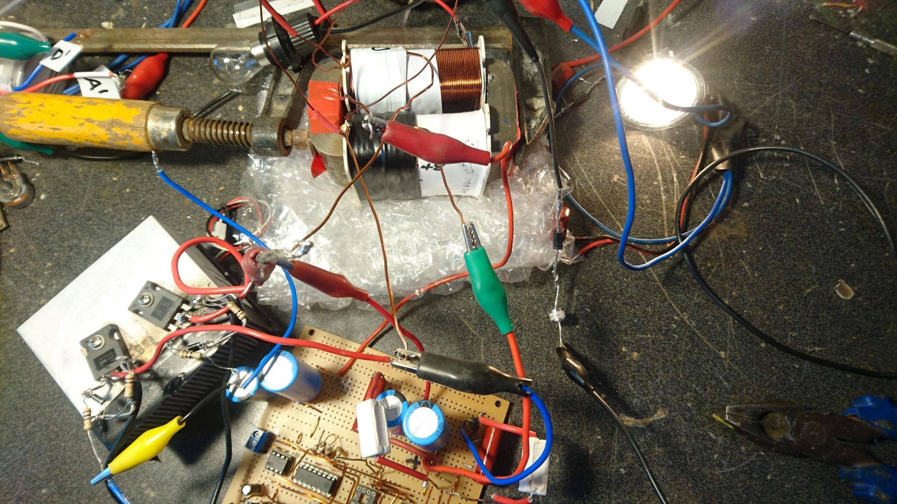
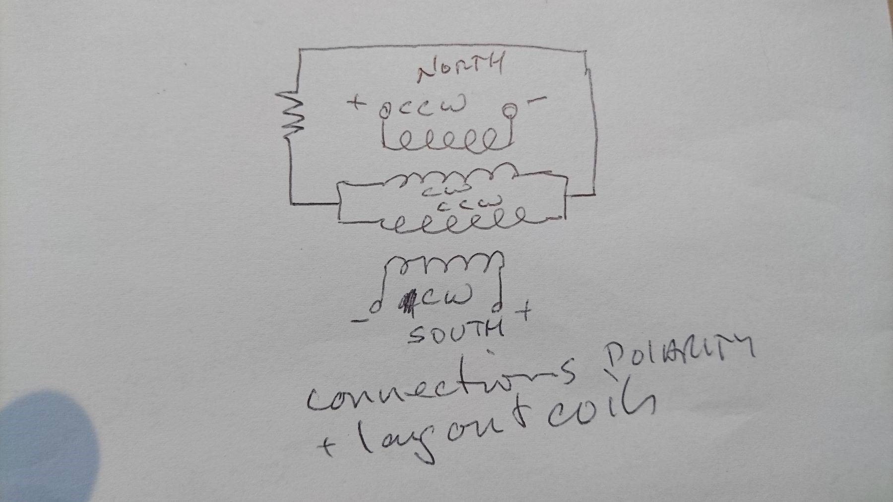
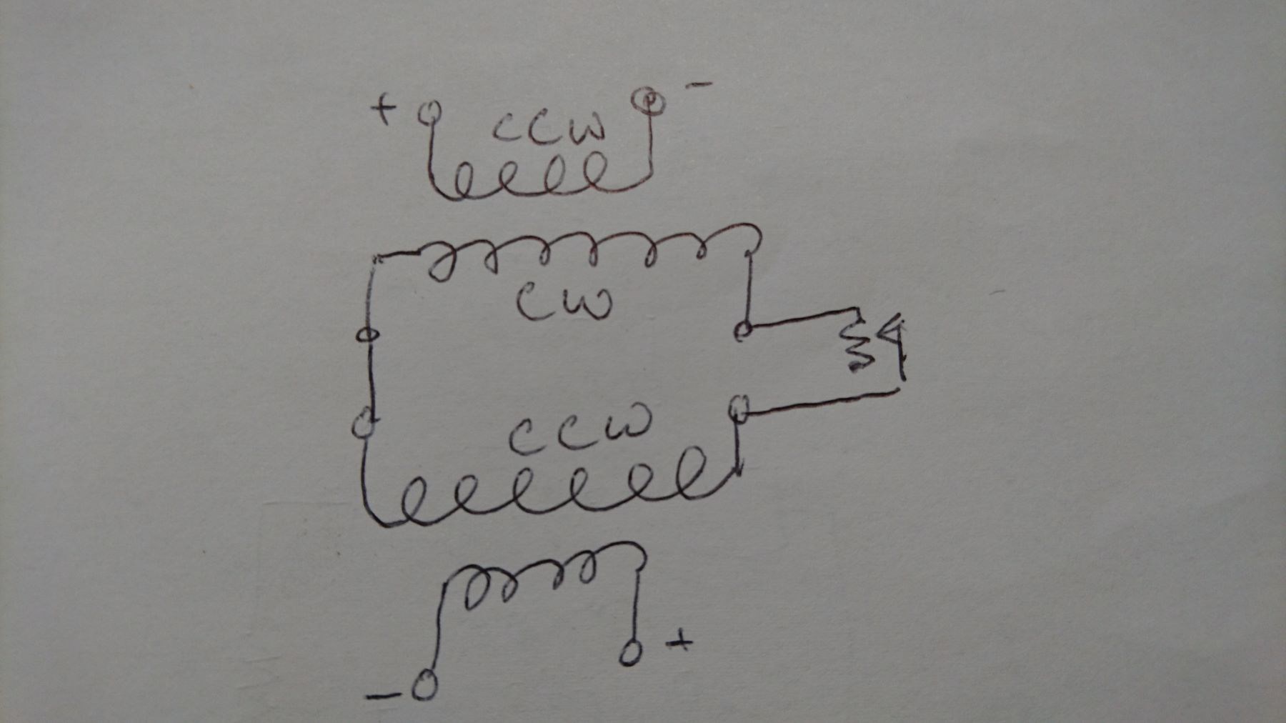
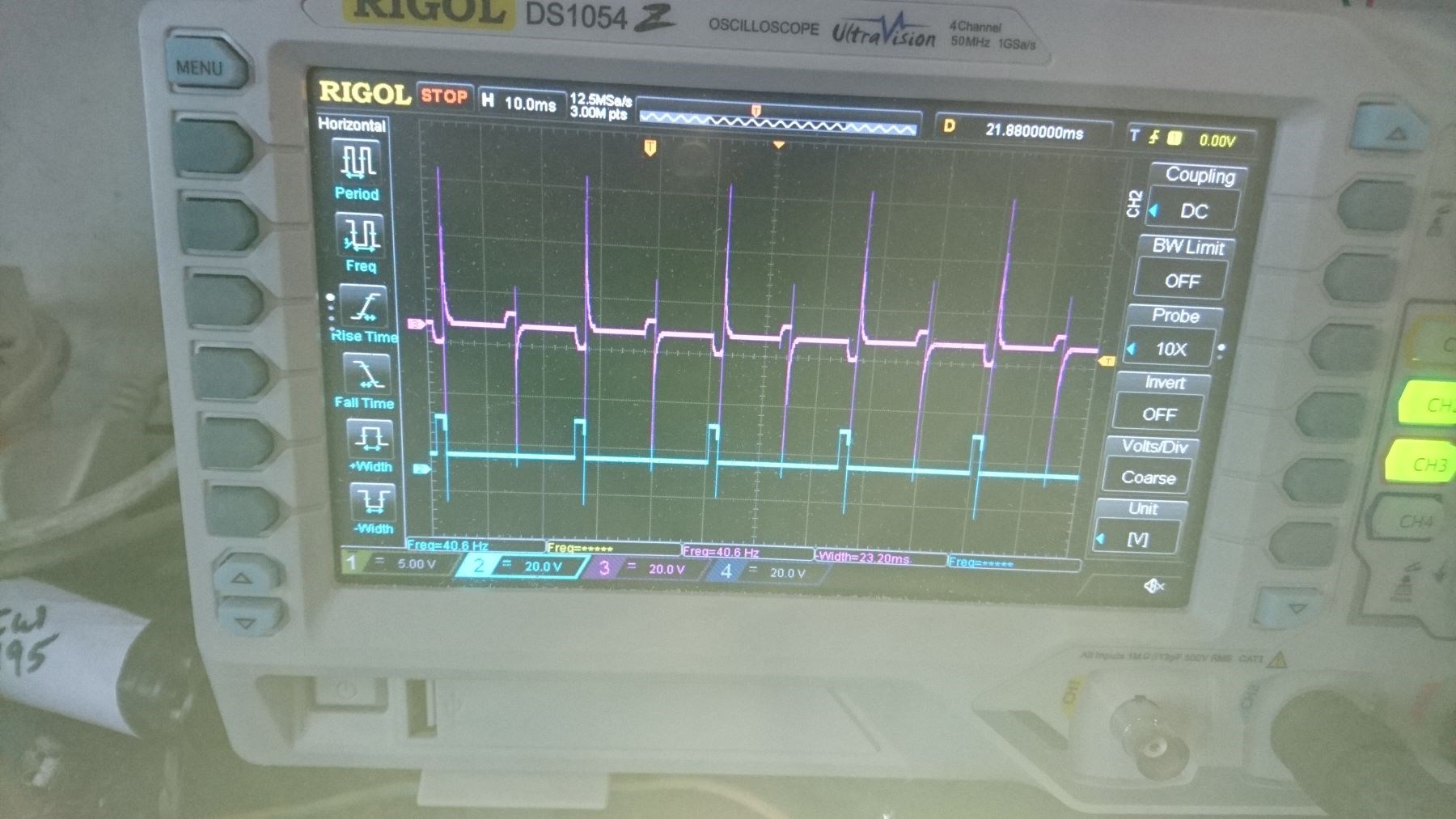
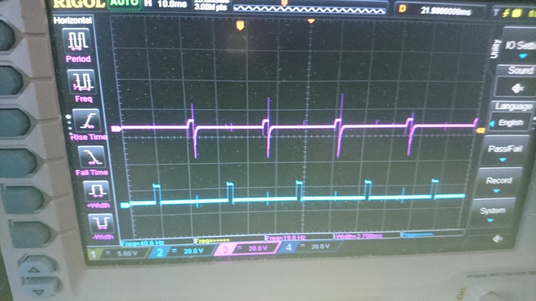
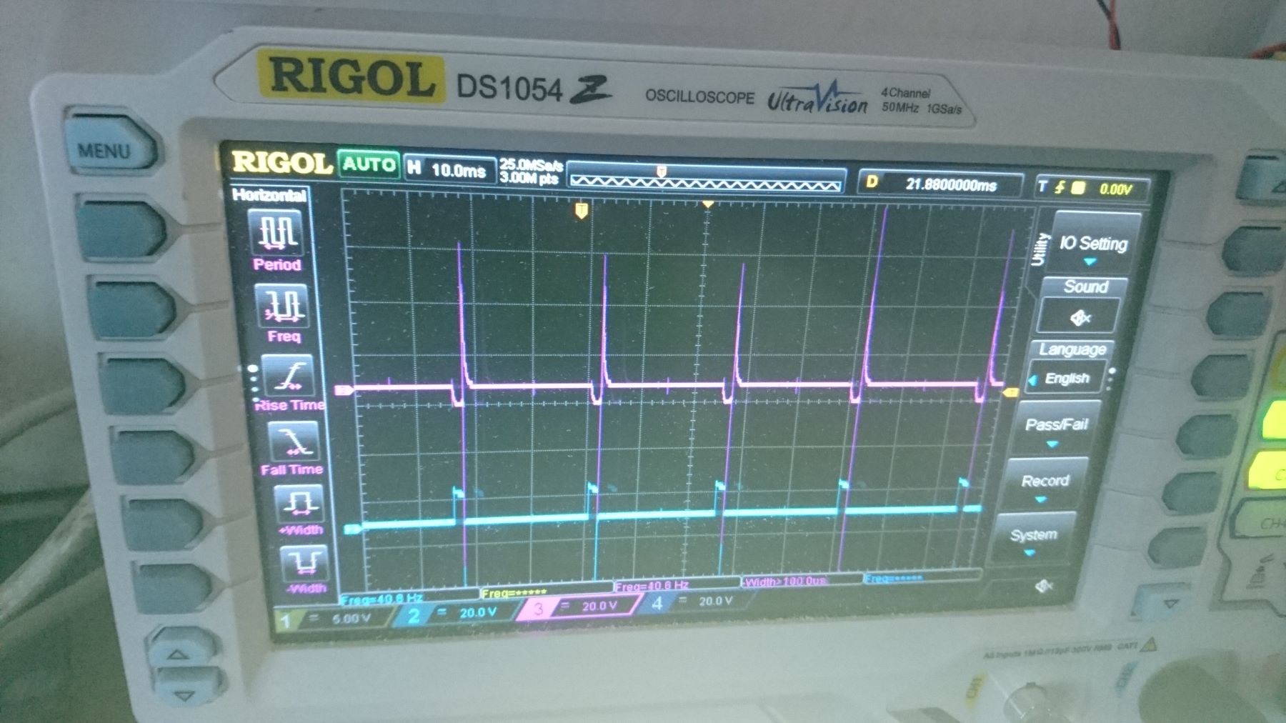
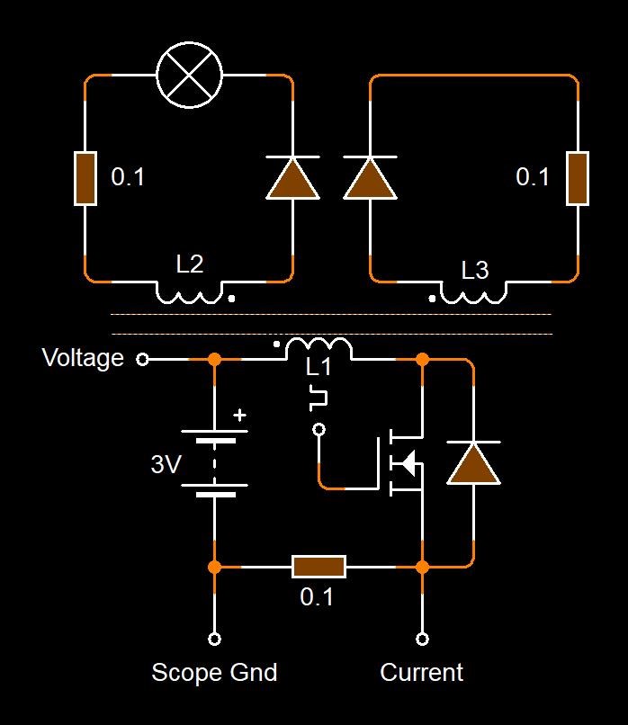
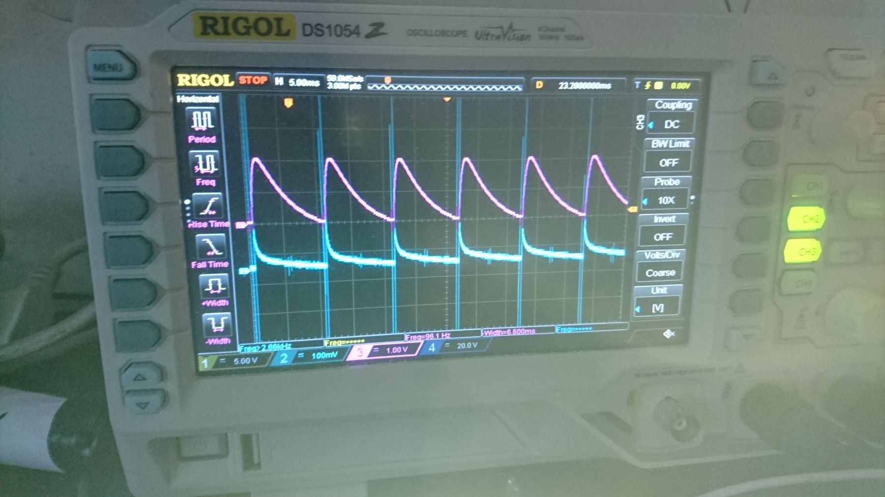
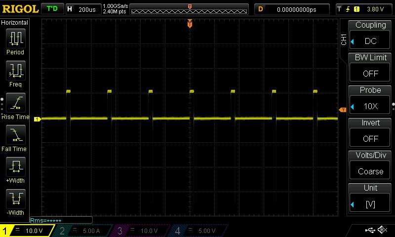
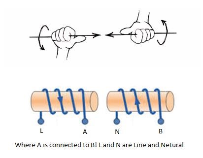
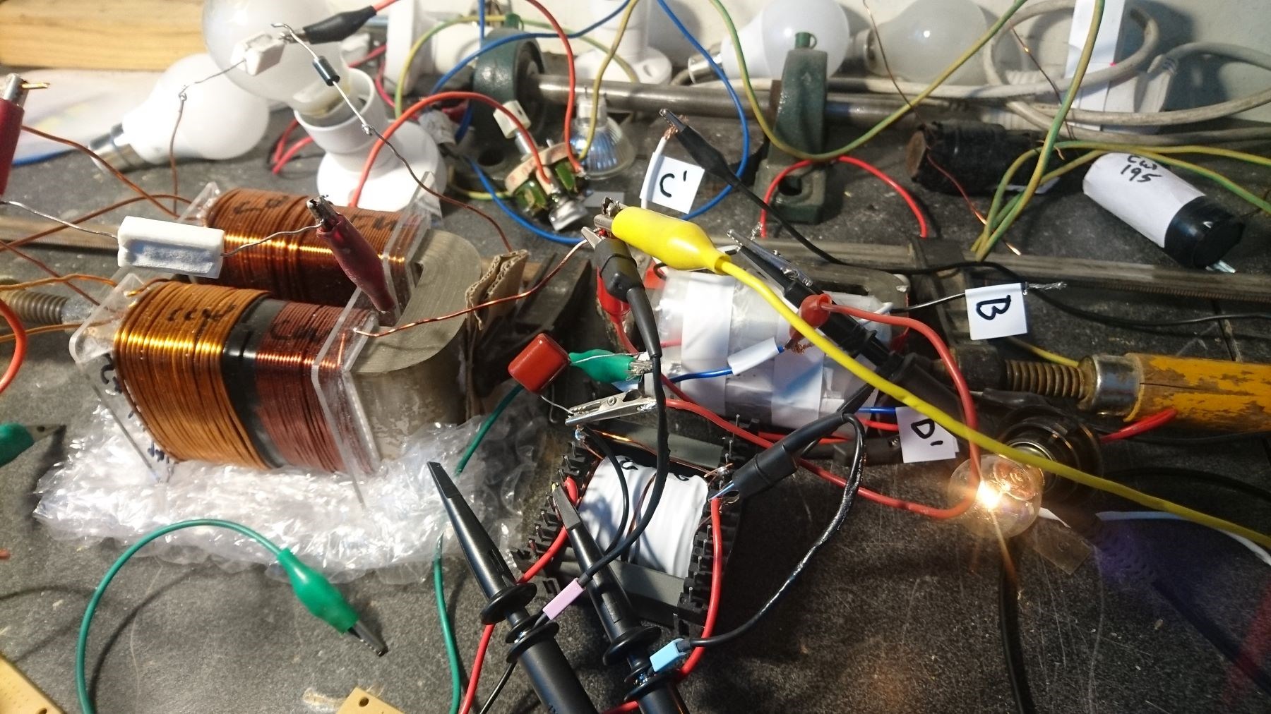
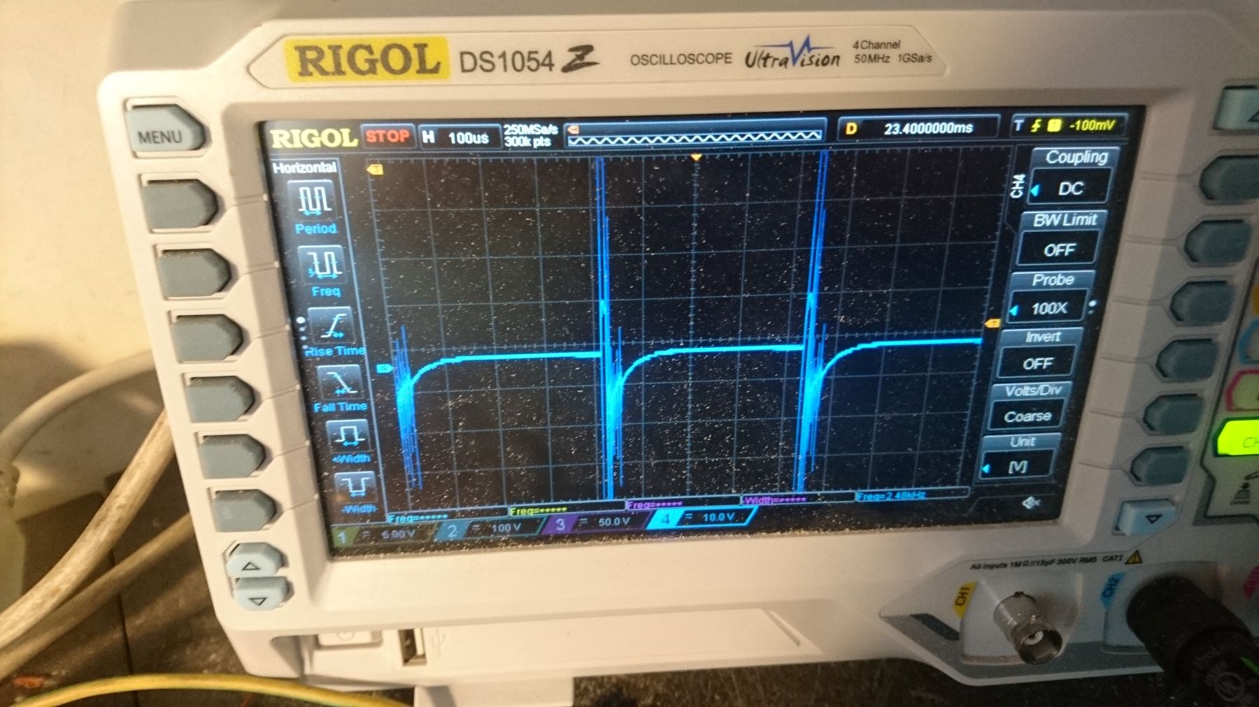
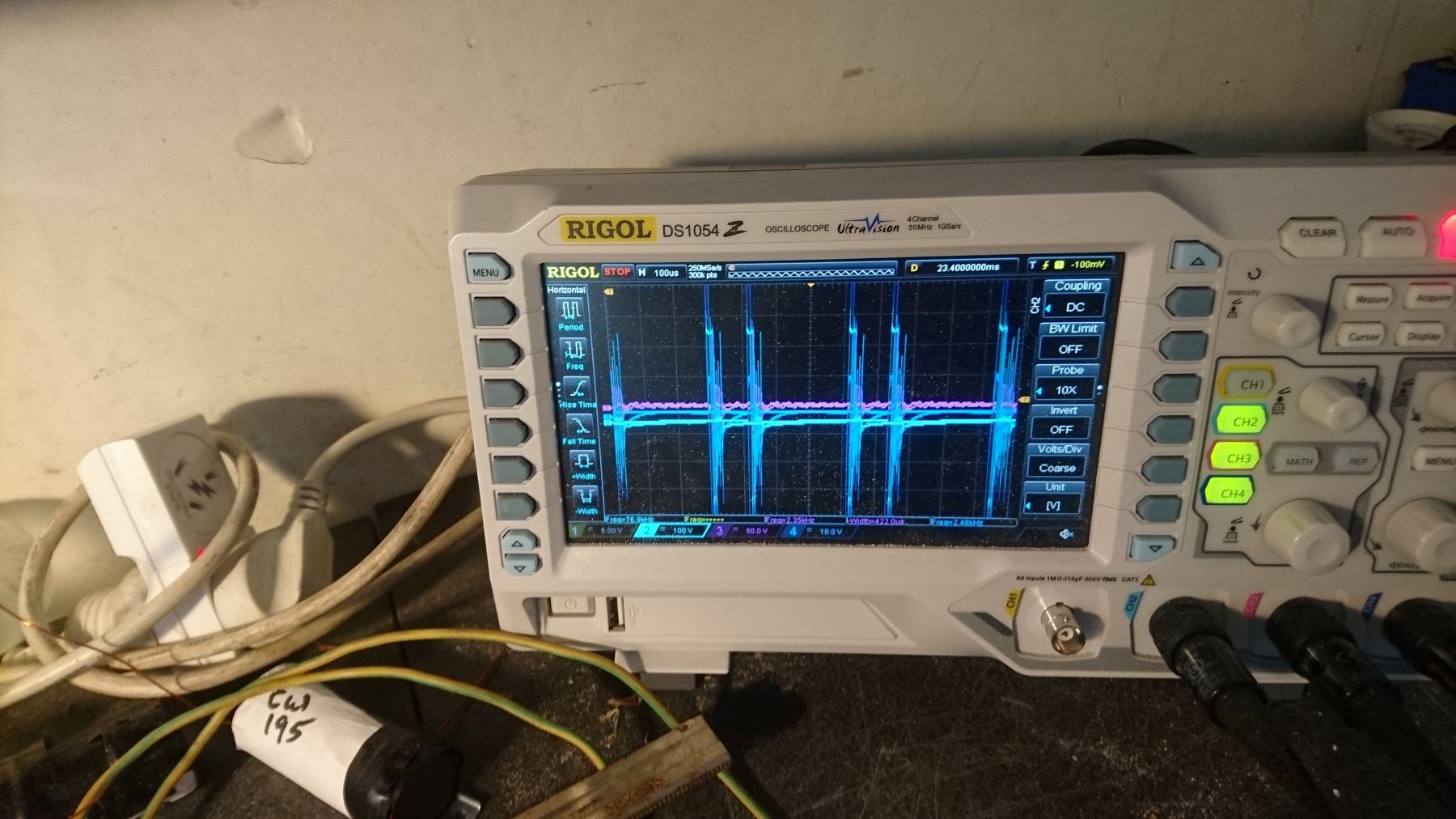
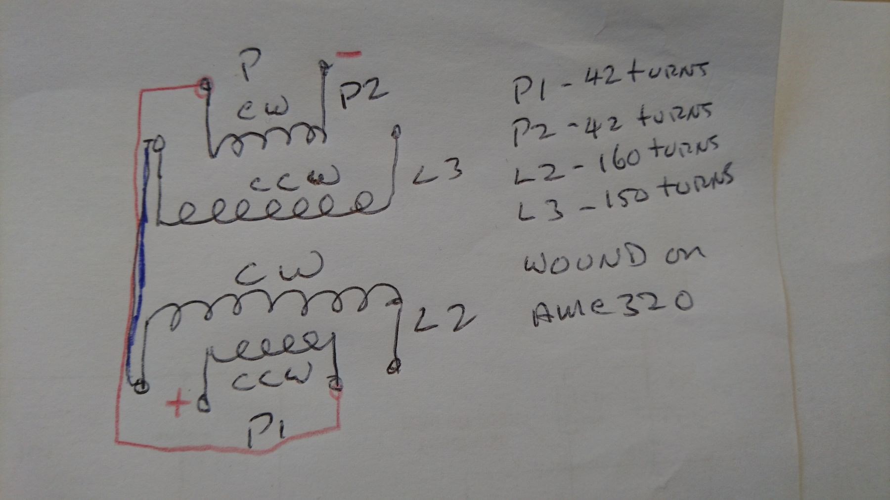
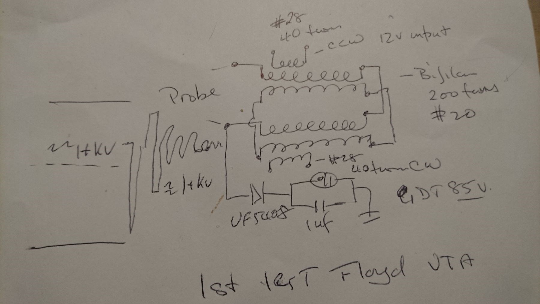
I have a standard pulse circuit into the basic bucking coil circuit. I am using a neon globe cross the primary coil which captures positive feedback. The coils are arranged as drawn, and with turns and gauge. I am showing diodes for taking off the load.

I get Outcome:

1) connect across positive going diode D1 and I get reasonable glow in globe;
2) connect across positive going diode D2 and I get very good glow from globe;
3) connect across Negative going diode D3 and I get outstanding white glow form glow:

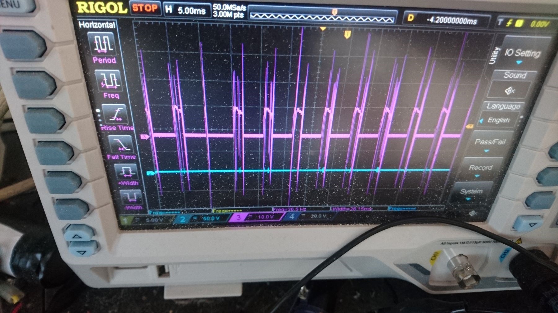
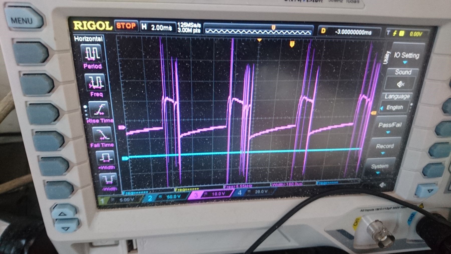
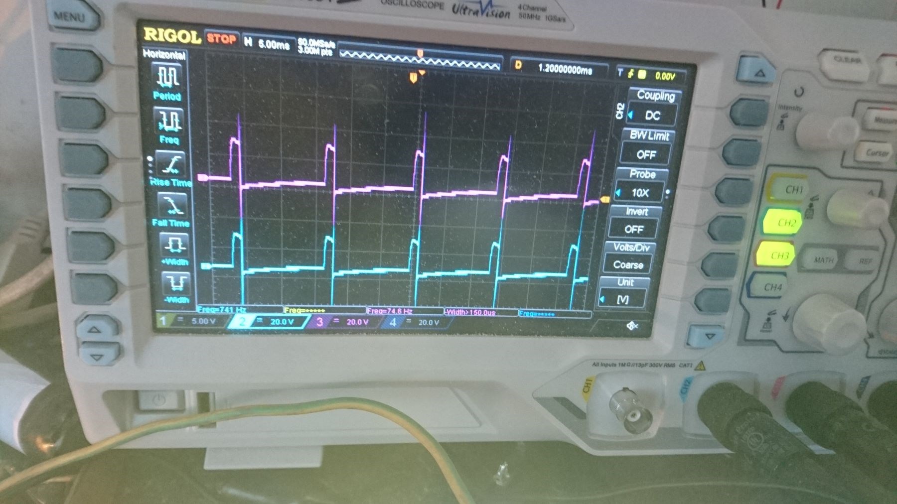
When I connect globe across D3, the instant power is connected the globe has great purple/violet flash. After couple of minutes for bucking coils to settle, I get violet bursts in the neon and violent bursts of white light in the globes. However, if I substitute a higher wattage globe the whole effect becomes muted. Prolonged exposure to the D3 source will cause damage to the circuit, neon and or globes!!

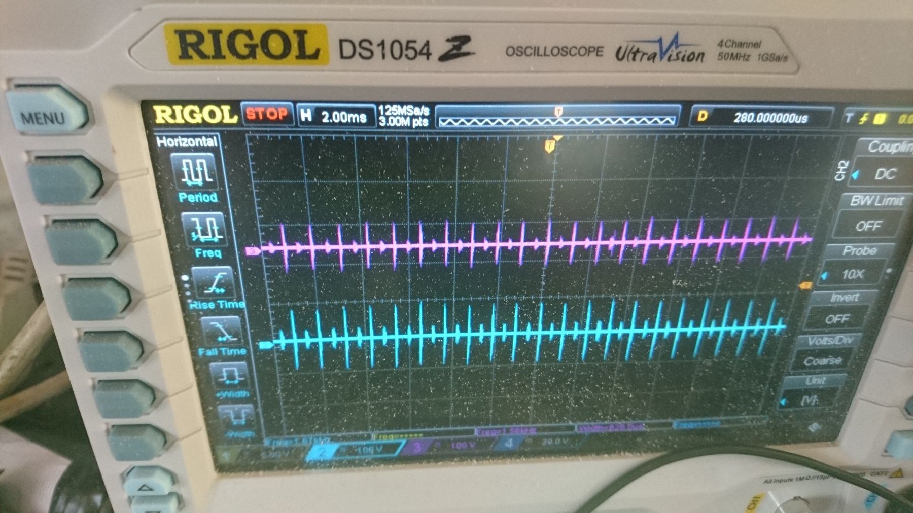
What I am not understanding is the direction of the A Vector as it travels through the coils. Although, it does seem to me that the purple glow is the radiant energy that I might be looking for as the alternate energy source. Further, The pulse from the feed back through the neon, with a small load connected to D3 is showing 1kv output on the scope.

Comments would be appreciated.

Acknowledgement of Atti's original circuit.

Regards

ourbobby

Order By: Standard | Newest | Votes
Chris posted this 13 June 2020

Hey Ourbobby,

Nice work! Yes, you are right, there is a Polarity to the Coils, the Input Current is an Indicator as to your best configuration. Of course, the maximum Output for the least Input, you should see your Input go down in Current when connected correctly. 

Wistiti shows just how this is done here:


You need to remember, there are limitations, the Flux Window [ B ] can only hold so much Flux and it can only change in a certain time. 

Like I said, you are on the right track! Make steps forward and you will soon look back and not believe where you are!

Best wishes, stay safe and well,

   Chris

Atti posted this 14 June 2020

Ourbobby


I’m not an expert on the subject, I’m just saying my opinion.
Don't stick to that drawing. If you observe Chris' drawing, there D1 is the other way around. Cd also used both variations. I don't know about others.
In my opinion, rather look at the outcome of the impact.
-Change iron cores if you can.
-Move near saturation (supply voltage, frequency, low primary speed, fill factor max 20%) I had the best performance there.
-Observe what the S2 coil changes and at what parameters! !

The Joule thief is a very strange device. Tends to cheat!
It changes its frequency under load. Especially if you change the polarity with the diode.

Decide at your own discretion.
(listen to everyone's opinions because they say a lot of good things, but don't listen to anyone)

Atti.

Chris posted this 14 June 2020

Ati is right, that's very good advice! Thank You Ati!

Best wishes, stay safe and well,

   Chris

Ourbobby posted this 15 June 2020

Hi guys,

             Thanks for the replies. I have witnessed many of the comments made. Such as the Flux limitations and the change in frequencies with load. Witnessing these events,  tend to encourage one to dig deeper.

However, my question today is, after exhaustive reading on Floyd Sweet, it is the process as illustrated in the diagrams of the basic circuits that I am unable to reconcile. Yet, I see that Chris has indicated in Part 1 of coil conditioning, that a figure 8 design might be appropriate. I have built a Caduseus coil to test and confirm outputs. The other similarity is the Mobius winding, which is more of a closed loop: such as an 8 shape, and might be the better method. I have not tested the Mobius coil yet, having the need to determine the best way to drive it. As it is a theoretical closed loop, for the VTA for me, flux coupling would seem to be the better option. But, I am not sure how one would set up the Mobius for bucking?

Further down the rabbit hole! I do not think that Floyd Sweet was trying to mislead anyone with the comment regarding magnet conditioning. I feel it is more likely that something he wrote or said was misinterpreted, to which misinterpretation he never corrected. If we interpret "condition" as a requirement for a better outcome a simple change of magnet size, for example, be a sufficient explanation for conditioning. No mystery here for me.

Edit: It occurs to me that I might be able to interlink two bifilar wound coils to get the Figure eight.

Once again, thanks for the feedback.

ourbobby

Chris posted this 15 June 2020

Hey Ourbobby,

Study is always good. I would like to say, it is however very easy to over complicate and thus confuse ones self, if one strays from the parameters of the current experiment.

To be blunt, regarding figure 8 Coils and so on, you are not on the best path forward if you follow that stuff. It is different and not related!

You will learn much more, and gain much more if you stick to your original experiments.

Best wishes, stay safe and well,

   Chris

Ourbobby posted this 15 June 2020

Hi Chris,

             Thanks for the advice. Too much cross information to look at. Just trying to get a handle on the Sparky sequence to better understand development.

regards

Edit: I now understand why I was unable to replicate the current sawtooth waveforms as per your demonstration videos! I was winding the directions that you had. But, I need different coil winding directions to you. I get the Mr Preva too!! And the Don!! Will attempt a full build and try to make a video.

ourbobby

Ourbobby posted this 20 June 2020

Hi guys,
have spent the last few days seeking what I think the output should be. L/Blue is output from Bucking coil S1 with small globe across coil. D/Blue is output from Bucking coil S2 to primary of center coil of Don Smith Tesla type output coils. Purple is output from Don smith secondary coils. I wound these Cw and CCW. I need more wire to wind both coils in same direction to test the outcome.

I think I might be on the right track with this output. I am waiting for some GDT's as the neon globes are not up to it! Literally burn up in a puff of purple smoke!!! Too much current/power being drawn for them. I am using the circuit above.

Regards

ourbobby

Chris posted this 20 June 2020

Hey Ourbobby,

I think you have switching problems again. Its not what it should be, that is, unless you are looking for something else?

Best wishes stay safe and well,

   Chris

Ourbobby posted this 20 June 2020

Hi Chris,

              Thanks for the reply, I am looking to utilise the Bucking coil set up as a driver for say a Don Smith outcome. I thought that what I should be looking for in that scenario is a modulated wave pattern, whereby, demodulating to a sign wave outcome seeks to utilise the pattern formation I thought I had correctly tuned to. This pattern is similar to that of a quarter wave superimposition?

Edit: I have used a 16:1 ratio that uses a multi strand primary coil, not a quarter wave.

Regards

ourbobby 

Ourbobby posted this 02 August 2020

Hi Guys,

               Back in the real world after my hip replacement. Still have restriction, but, I can now go up to my workshop. I have wound this small meg type arrangement. This is what I am getting with 12 volts in low current. I am thinking that one of my coils is still back to front!

Regard

Ourbobby


Chris posted this 02 August 2020

Hey Ourbobby,

Wishing you speedy recovery!

If I may suggest a Switching module from Vidura or something similar? It appears you are still having trouble with the Switching?

If you focus on a 10% duty Cycle at say 3 Volts Input, and make sure you have a nice clean fast Input Pulse. This will make for the easier Experimentation on this configuration!

Good Work! Nice to see your'e onward and upward. I used to have the exact same problems and it took me quite some time to learn the best practices of the Switching of Mosfets / IGBT's and so on.

We have several threads to help with Swittching:


I hope this helps! I am sorry if I am wrong, but there appears to be no clean switching in there. So I am sorry if this was your goal!

Thanks for sharing, best wishes, stay safe and well My Friend,

   Chris

Chris posted this 02 August 2020

Hey Ourbobby,

Another option is presented here: Microcontroller PWM cheap and easy start to getting something working

I hope this helps My Friend!

Best wishes, stay safe and well My Friend,

   Chris


Ourbobby posted this 03 August 2020

Hi Chris,

              I think I get it now. I read somewhere that the bucking coils themselves will not provide the answer we might be looking for. Increasing output coil winding will give us HV for low voltage input. I missed that point a while back,

I think this photo is similar to the outcome we are looking for?

Regards

ourbobby


Chris posted this 03 August 2020

Hey Ourbobby,

If Total Input Power is 1 Watt and we want to go Above the Unity Boundary, then we must have our Machine Output in Excess of 1 Watt. You with me? 

The Watt ( W ) consists of 2 Units:

  1. Voltage ( V ).
  2. Current ( I ).


This we know.

So, 1 Watt Input, if we have 2 Watts Output then we are Above Unity. How do we get our Coils to "Generate" excess Energy over Time? Volts and Amps?

Voltage step Up steps up the Voltage, but reduces the Current. So how do we Increase the Current?

The Mr Preva Experiment shows us how to do this, its a case of Bucking Coils as we saw in Tariel Kapanadze's Machine:

Ref: Post Here


Tariel Kapanadze used two methods of switching, Push Pull Mosfet Oscillator and a Spark Gap.

I refer you to this video:


Which was replicated by Aliaksandr Shpak here:


Also another here by WolnaEnergiaTeraz:


Of course, combine these two circuits:


We must learn to make the Coils Resonant, and at that stage, Energy is Pumped from the Environment.

There is tons of information in my pages, perhaps t much to read for the average person, but my point is, I have covered this many times here on this forum. We must focus on the basics, Voltage, Step Up, and Current Magnification.

Best wishes, stay safe and well My Friend,

   Chris

Ourbobby posted this 04 August 2020

Hi Chris,

              Thanks for the reply. I thought the photo i uploaded suggested a resonance. Anyway, I have never been able to see through the conglomeration of Tarial Kapanadze's coil structures. I guess too, so might many others! For one there is never any in depth photos that enable a viewer to establish his connections.

Regarding the watts. although you mention V x I, is it better to look at I2 x R. No Load equals no gain? There is something sticking in my mind from the Don Smith Videos' That is his use of reactive voltage, which is then demodulated to capture voltage variations, which in turn alters the frequency of output. This is still high voltage, and he then uses an earth return to capture the ambient current . His starting point is the Tesla coil where he has taken, what I think is very low current high voltage, and then massages this to a usable  energy output. I think, his classic piece of work, that all are familiar with, which is the two coils with the sliding primary, pumped with a NST, are two bucking coils?

When I am bucking my small test rig, as above,  during noisy bucking, when opening up the pulses, I get a series of what looks like an AM modulated wave. So what you are saying, is that this is not what i should be seeking?


Regards

ourbobby

Chris posted this 04 August 2020

Hey Ourbobby,

We must have a Bucking, or two Magnetic Fields oppose each other in the Output Coils.

If we can get nice clean switching on the Input, we can put a short pulse in, to get the Voltage up and let the Coils and Fields do work on their own accord.

The excess work period is where excess Energy lays, in the Time Domain. Follow Baerndorfer's thread: Can we measure magnetic flux with an oszilloscope for more information on Area Under The Curve. This area is where we can see more work being done.


You had it spot on Here.


I believe, if you can get your switching fixed, you will soon be back on track!

Best wishes, stay safe and well My Friend,

   Chris

Ourbobby posted this 04 August 2020

Hi Chris,

              Please excuse me for being pedantic. Its a character flaw! I have just rearranged one of my other Bucking 

coil set up for simultaneous hand shaking! The problem I have is that I do not have a constant current power supply. The current goes haywire. What I am getting is a constant vibe! If you don't mind, do these wave shapes indicate my progress?

Regards

ourbobby


Chris posted this 04 August 2020

Hey Ourbobby,

I don't believe this is to do with your Input Power Source. I may be wrong, but that's my opinion. I believe the Mosfet is not turning On and turning Off properly. I think there is Noise at the Gate of the Mosfet and that's why I suggested to fix the switching.

Perhaps if you can probe the Mosfet Gate and show us the signal there?

Years ago, I saw Gate bounce in some of my work, that's how I recognised it. There are a few methods to fix this, E.G: a Diode on the Gate ( D3 ) to the Grounding Resistor. I have posted these Circuits on the prior links I gave you. Here is an example:


Most engineers do not employ this technique these days still. Really good engineers do!

Best wishes, stay safe and well My Friend,

   Chris

Ourbobby posted this 04 August 2020

Hi Chris,

               I will endeavour to get some clear shots of the gate in slow time. At the present time I have a 15v zener  and 10k across each gate. I am using irfp460. It is possible that my source of fets is suspect maybe.

Edit: which diode would you recommend there?

Edit 2: I have put schotsky diodes on the gate. I get an improvement with output.Pulses do seem to look a bit cleaner. So that confirms your suspicions. Good call. However, I am getting through feedback over 200v at the gate!! which is a reproduction of the bucking coils behviour. I think I might have to isolate the drive circuit and the fet.

i

Regards


ourbobby

Chris posted this 04 August 2020

Hey Ourbobby,

The best Mosfet Circuit is from, and including, the MCP1403, all the way through to the connector. Each component having a purpose.


Also, very important to keep wires very short, ideally if you don't need a wire, don't use one, sort of thing. Fast hard Switching.

These rules make for better reliability for the Circuitry also.

Best wishes, stay safe and well My Friend,

   Chris

Vidura posted this 04 August 2020

Hey Chris, You have inversed pins 6 and 5 in this schematic, the MCP drivers have the output on pin 6 and 7.

Vidura posted this 04 August 2020

Hey Aloha!

An interesting tecnique, I will try it when I can. for the moment I have some issues with my scope. The comments about the flux modulation is quite interesting as well, it might be related in this thread here 

Will see foreward to make some bench work on this topic soon

regards Vidura

Chris posted this 04 August 2020

Hey Chris, You have inversed pins 6 and 5 in this schematic, the MCP drivers have the output on pin 6 and 7.


Hi Vidura,

The MCP Series changed just after the 1403/4/5. The MCP1403 Datasheet shows the Pin Outs:


I always run on the Datasheets, I learnt the hard way! Mistakes are expensive!

Happy to look at possible Circuit Errors however if I have any? I have checked my diagram and the pins you mention, are in fact correctly laid out.

I post the Circuit again for your reference:

I hope all here take a good close look, it is very easy to mix the pins up, and connecting the wrong pins will result in very bad failures!

@Aloha, nice to see you back!

I have to say, in my years of research, Motional and Variational are the inverse of each other. As Flux Varies, it is Motional at the same time. As Flux is Motional, it must sooner or later become Variational. Flux can not be static, yes you are right!

To quote an old friend of mine:


Yes Sir, a Time Varying Flux Must be Produced! This is the first and most critical component! This we know, and this we have done! We know what needs to be done and we have achieved the basic Goal, we now only need improve on it!

If you can read between the lines, the next sentence is critical also, Floyd tells us: This must be caused to vary in sync with three modulating signals...

  1. Primary Signal.
  2. Secondary Coil One.
  3. Secondary Coil Two.


The file attached below, I am sure everyone has it allready, but if you dont: Original Sweet SQM files.zip

Best wishes, stay safe and well My Friend,

   Chris

Attached Files

Ourbobby posted this 05 August 2020

Hi Chris,

              This is the best I can do at the moment. I have taken out the GDT from primary coil and replaced it with a 50ohm resistor. I cannot seem to get rid of the lagging oscilations. The biggest issue seems to be the feedback through the coils to the original pulse circuit. I am not sure what a time varying flux is. At the moment I am trying to get the best out put result. It is possible that I need to rewind the coils for a different copper weight. I have also noticed that if I connect a short circuit between L2a and L4b from the anode of diode to cathode and the same for L4b and L2a . This is probably meaningless, while i search for the mind blowing discovery of overwhelming energy.

i have two  arranged sets of Bucking Coils opposing each other. L1 = primary L2 Secondary: L3 primary and L4 secondary. So above, I am cross joining the outputs to see what effects I get.


@ Aloa and Vidura,

                               Thank you for your input guys. There is a lot happening with these coils. Takes a bit of time absorbing and getting a handle on it.

Regards

ourbobby


Chris posted this 05 August 2020

Hey Ourbobby,

That's Gate Signal yeah?

Awesome work My Friend! Looks leaps and bounds better! A massive improvement!

Don't worry about "Time Varying Flux", just think movement of Flux. A Moving Magnetic Field is our Primary Catalyst!

Your'e doing great work Ourbobby, I am sorry for being the one that points out problems, I only want to help! That's why I do it! So please remember, I am only trying to help where I can. Switching can be hard, there is a lot to know and think about if one is new to it! All of us here are sharing our experience, and that's what makes us so awesome!

When you say:

This is probably meaningless, while i search for the mind blowing discovery of overwhelming energy.


This can happen, so yes, please beware! Normally it happens when a sharp pulse is present, the fast Time Rate of Change of the Magnetic Field. At this point it is very easy to blow everything to high heavens! Not a desirable effect.

What I am sharing can do that!

By ensuring your Coils are ALWAYS Loaded, this reduces the risk. Magnetic Field Control!

If I may, when I started, I was of the same mind set. A spontaneous surge of Power. I quickly learnt that in most cases, one has to work at this. Making small steps forward, improving your machine over time.

Your'e doing great work, keep it up!

Best wishes, stay safe and well My Friend,

   Chris


P.S: The spike maybe stray inductance, check your Wire and Trace Length. Shortening lengths of Wire and Traces might reduce this. Also, check your resistors, wire wound resistors could be a problem also.

Ourbobby posted this 05 August 2020

Hi Chris,

              Thanks for the encouragement. There is one thing. The two sets coils I am working each have a primary and a secondary. Mostly I read about only three coils unless it is the MEG. The Meg which I think is different?

Regards


ourbobby

Chris posted this 05 August 2020

Hey Ourbobby,

All of these machines work on the same basic principles. The may look different, have another Coil here or there, but the method of Generating Energy, by Opposing Fields that is not your Input Coil and Output Coil, E.G: A Symmetrical System, is the same.

If Energy is equal to Work, and our Machine's purpose is to do more Work than what we put into the System, then the Work must come from somewhere!

The Partnered Output Coil Interactions do this extra Work! This can't be done with only one Output Coil! There is a requirement that there be Two! The two Coils must be at least partially loosely Coupled. 

Best wishes, stay safe and well My Friend,

   Chris

Ourbobby posted this 06 August 2020

Hi Guys,

              Unless it is an increase in voltage and constant current, I am not sure wher to head off to with this project. Some point I have notices. When tuning frequency, I can get "splutter" and massive increases in current. If I test for magnetic polarity, I get North on one flat side of double C core and South on the opposite side. The attached illustration (rough out) shows the connections for driving. Top of drawing corresponds to North when operating. The best output I have gotten is from this set-up. Which, to does not mean I have the correct protocol! The pulse is scope probe across the globe or either side shall keep my eye on that. of the parallel output. It makes little difference if I use diodes. I have placed a recovery "Bedini" type diode to battery negative. I would not know how to calculate the resonance of this set up where all coils have different winding turns! All I can hope for is that pure voltage and not current will improve the energy output without resonance.

Regard


ourbobby


Ourbobby posted this 07 August 2020


Hi All,
I have gone back to basics! I am starting the process from the beginning. I have amorphous C core, two secondary cores wound CW and CCW with slightly different winds, 160 and 150. The two primaries are wound Cw and CCW 40 turns each. The set up of the coils is as above diagram, with the exception of the output. I think my previous output method was transformer similar. Adjusting the input to low current, I have obtained the "Noise"!! To achieve this I have placed a variable resistor across the output, as in diagram. The is an optimum increase range for the resistance before it make no further change to output. In this instance the range is 0 to 20 Ohms It makes no difference on oscilloscope if diodes are used. I think the attached output shapes are what I should be looking for. They are frequency dependent for increase in voltage. I have not been able to get a light globe to work on this output. Maybe I need a small globe to start with, which I do not have. Input voltage 12v current approx 250ma

Photos: purple is outputs across resistor, blue is one of the inputs.

Regards

ourbobby


Chris posted this 07 August 2020

Hey Ourbobby,

If I may recommend, stick to the original Circuit, study in detail and do not deviate from this circuit until you know 100% all interactions and operations:


L2 Opposes L1 but L3 Assists L1, this part is important!

Deviating from this circuit will result in failure and then you will loose interest.

  • Learn why this works!
  • Learn how this works!
  • Learn how the Interactions are critical!
  • Learn about the Coils and how they work together!
  • Learn why we need two Output Coils!
  • Learn how to get the Output Voltage Up sufficiently to get a good Output.


Learn about the whole thing before you change anything. If you change it, without knowing how it works, then it soon becomes a futile effort.

Test the difference between One Partnered Output Coil Clock Wise and One Partnered Output Coil Counter Clock Wise, whats the difference between Turns Directions?

There is tons to learn! CD may be able to give you some advice here?

Best wishes, stay safe and well My Friend,

   Chris


P.S: Your switching is 100% better than it was, nice to see you have got nice switching!

P.P.S: ALWAYS Load your Coils!

  • Liked by
  • Jagau
  • Augenblick
Ourbobby posted this 07 August 2020

Hi Chris,

             Once again, thanks for the assistance. I suspect you might be getting a bit tired of my inability to grasp this concept. Anyway, I haven't got a 3v power supply yet, so I have used the 12v. To get the triangle I have had to increase the resistance on L3. I recall doing that with the photo you put up to remind me that I had already been down that track. I hope this is what you wanted me to show on the scope. Don,t know why the peak is rounded: L3 and L2. Hmmm.......... All I can think of is the discrepancy between winding turns with L2 and L3. Also, don't get much vibration with this test!

Edit: If I run two primary coils alternatively, I get two sawtooth waveforms is the same space as if running one primary and getting one sawtooth.

Regs


ourbobby.


Chris posted this 07 August 2020

Hey Ourbobby,

Don't worry about the 3 Volt supply, just use Duty Cycle, start from 0.1 and slowly move up in duty Cycle.

I don't believe your coils have the right polarity.

Your scope shots look good, but your'e not quite there yet. Make POCOne oppose L1, your primary. Then make POCTwo oppose POCOne, but assist the Primary L1.

Then, once you have done this, tune Duty Cycle, Frequency and Input Voltage, to get the best output. Learn how to improve the setup, increasing the COP as you learn more.

You should have very linear scope traces when you get this right.

If this is your input:


And the area under the Trace to Zero is more on the Output, then you have more Output than Input, please follow this thread for this method: Can we measure magnetic flux with an oszilloscope. Lots of great work done by  Baerndorfer.

You can do it Ourbobby! Stick at it and don't give up no matter what! You have 95% of it, its just a case of bench work now to make sense of the rest.

Best wishes, stay safe and well My Friend,

   Chris

Ourbobby posted this 07 August 2020

Hi Chris,

             You could be correct on polarity. I have tried manipulating the direction of the connections. I really need to wind  a few more coils. The issue is, with the C cores it's getting the bobbins!  I am looking at a small CNC cutter for the assembly of bobbins so that I can wind multiple coils to measure the differences between polarities and winding turns. 

I get the position of the Bucking coils, I think. I have been in dream land, thinking they were an independent unit for power generation and output! I now do not think that the C core configuration  bucking coils will give a final output: although I might try a mazilli on one of my set-ups to see what happens!. What the bucking col notion does is to provide the input  to another output stage, as in the French guy's video in a retreat in France. Ultimately, there is only one method. As Don Smith stated, once he understood how it worked, he spent his time looking at different methods of achieving the same outcome! 

There was me thinking that there was a short cut! Always the optimist.

Edit: Incicentally, the duty cycle in the above photo was less than 10%. I had turned the duty cycle back to zero and then progressively "inched" my way up for minimum current, max noise, and tight sawtooth; that is no space between pulses. I reckon it was approximately 7%

Regards

ourbobby

Chris posted this 07 August 2020

Hey Ourbobby,

Yes, Don Smith was very wise!

Once you become so very familiar with the Coils and how they interact, this does become a lot easier. But one does have to make initial head ways first. Don was right, he showed all, its just to many smart people dismiss Dons work and label it as a hoax with zero knowledge of Power "Generation" techniques! Those smart people shoot themselves in the foot and also everyone else that listens to their total non-sense!

Watch and familiarise your self 100% with this video:


NOTE: Apply Dons Circuit to this Image!


Follow the Right Hand Grip Rule, this was the advice from Floyd Sweet also:

FIELD SUPER-POSITION AND THE VACUUM TRIODE:

Electromagnetic induction with no measurable magnetic field is not new. It is well known that in the space surrounding a properly wound toroidal coil there is no magnetic field. This is due to the superposition of the fields.

...

Consider for a moment the construction of the triode which includes the bifilar coils located within the fields of the two magnets.

When the current in one half of the conductors in the coils (i.e., one of the bifilar elements in each coil) of the device is moving up, both the current and the magnetic field follow the right-hand rule.

The resultant motional E-field would be vertical to both and inwardly directed.

At the same time the current in the other half of the conductors in the coils is moving down and both the current and magnetic field follow the right-hand rule.

The resulting motional E-field is again vertical to both and inwardly directed.

Thus, the resultant field intensity is double the intensity attributable to either one of the set of coil conductors taken singularly.

Ref: Floyd Sweet - Nothing is Something


Stick to the simple rules and it is easy to succeed!

Floyd Sweet tells us:

Electromagnetic induction with no measurable magnetic field is not new.


His machine was, as was all of these machines, a Solid State Electromagnetic "Generator"! Using the simple rules of Michael Faraday, Faraday's Law of Electromagnetic Induction!

Best wishes, stay safe and well My Friend,

   Chris

  • Liked by
  • Augenblick
Ourbobby posted this 09 August 2020

Hi Chris,

             Well, had a surprise on the work bench this morning. I have also been working with a coil from Med 3012's ETBC. I show a photo of the outcome. The ETBC is not connected to anything, except a globe, and the connections are not formalised! Neither is the large bucking coils to the left, has no power connected. All I had connected is a small transformer that I had wound to drive a variation on the Mazilli circuit I found on Hackaday forum. I have been having trouble getting it working. So I connected the transformer to an existing Mazilli on same board to confirm transformer working. If you look as the rat's nest, I have pushed large bucking coil in closer ( made no difference) you will see unconnected ETBC and light globe working!! Freak set up! My large bucking coils to left are wound 160 turns, the small transformer is wound 85 turns. ETBS is only about 10 turns. So there is some resonance going on here! One final point, required earth connection through probes!!

Have to stop and think my way through this opportune discovery!

Edit: There was one unusual thing, The Mazilli was drawing amost no current, but the mosfets, IRFP460, were running very hot. I had to keep stopping the show to allow them to cool. I take that to be poor gate drive?


regards

ourbobby


Chris posted this 09 August 2020

Hey Ourbobby,

Great work! Big steps forward by the sounds of things! Some advice, document, video, draw circuits make sure you have everything 100% covered, as understanding is gained, you will make more sense of the results! Well done!

Best wishes, stay safe and well My Friend,

   Chris

baerndorfer posted this 09 August 2020

Aloha alohalaoha!

in the image above - what do the numbers mean? i always think about an intelligent way to connect POC coils together in one toroid. if the goal is to amplify the magnetic field then we will need B-fields from the POC's which point in the same direction in every moment in time. right?

what also should be noticed is, that it makes a hughe difference if the coil is switched on the low-side. in other words... if i change the switching on my coil from highside to lowside the responce from the coil is bigger. more energy involved for some reason.

thank you very much


  • Liked by
  • Augenblick
  • Chris
Jagau posted this 09 August 2020

Hi Aloha


the differential configuration (last one) is a closed loop.

I don't really understand where is the Tx and the RX?

Jagau

Ourbobby posted this 11 August 2020

Hi Chris,

                Just a quick question. I have an AMC 320 core, windings on each leg. One leg has L2 CCW with P1 on top with CW, other leg has L2 CW and P1 has CcW. Now I know that the configuration might be off a bit. However, the question relates to understanding what out put I am looking for. I have serial connected the two P1 windings for maximum effect, and serial connected  the L2 coils with a diode between the L2 coils. I cannot light a globe, but, I am getting the buzz and with 12 v input very high voltage out over 2Kv, goes down with load.  The flux meter goes off the scale when a few inches away from coils. Is this a good situation?

Regards

ourbobby


Chris posted this 11 August 2020

Hi Ourbobby,

I am not sure I understand your question.

Standing Wave is the Goal, between the two Output Coils:


A Configuration where, once we have resonance, we get greater Power, ( V x I over time ), is greater on the Output than the Input.

Confusion is a common problem with this technology, perhaps going back and reading the fundamentals: Builders Guide to Aboveunity Machines, may be worth while?

Force yourself to focus on the basics Ourbobby, or you will end up wasting your time!

Best wishes, stay safe and well My Friend,

   Chris

Jagau posted this 11 August 2020


Hi Alo

If I read the definition of the Hooper patent coil:

The present invention relates to an all-electric generator producing an emotional electric field in the space surrounding the device, but not requiring any mechanical movement of its parts to generate this field. The theory underlying the production of such a field postulates that each moving electron constituting the current in a linear conductor carries with it a loop of magnetic field energy.

We recognize in the description the loop you are talking about. I'm going to study Hooper's patent. It seems interesting to me for my research.
thanks Aloha for your help

To Ourbobby

Could you draw a diagram of the problem you mentioned, maybe we could all help you solve it?

Jagau


Ourbobby posted this 12 August 2020


Hi Guys, 

              Thanks for the response!. First let me ask the question what is a Static Resistor? I am thinking it is a point in a cycle where fluxes or induced current forms a sort of block, not from the absolute resistance of the circuit, but one formed from resonance.

@ Jagau,

                 Thank you for your reply. I have attached a drawing to try and illustrate what I did. I have two main coils L2 and L3 wound CW and CCW, 160 and 150 turns. Wound over these two coils I have two primary coils. My original intention was to observe the bucking reaction  using either simultaneous pulsing or alternate pulsing. Then I later noticed this large coil oscillating when sitting on the bench not connected to any device. I was conducting another test using a small coil with 80 + 80 turns  into another set up: explained in a post above. What occurred to me was that as the two L2and L3 coils were joined together, that my primary coils were actually not working to a full capacity. It is when I connected the two primaries together that I git better output through a globe than if they were not connected. I suppose, on reflection joining coils will affect the final resonance. I also got from output of L 2 and L3 very high voltage, measured on my scope with 100 x probe several Kv's. I have rewound P1 with heavier 1:4 guage wire with 6 turns. I shall see what happens here. 

Regards

ourbobby


Chris posted this 12 August 2020

Hey Ourbobby,

Every experiment is an opportunity to learn something of value!

I do feel you are going off track, but I will leave this up to you to decide what your path is. I do not wish to tell others what to do, I only offer guidance when asked for. This I have done.

Best wishes, stay safe and well My Friend,

   Chris

Ourbobby posted this 13 August 2020

Hi Chris,

              You are most likely correct. I am looking at the Floyd Sweet diagram at the moment. I think I get the central coils, especially after spend a moment looking for the bif wire gauge! The thing I am tossing about at the moment is what is meant by 240 turns.  There are three options here. I am leaning towards 240 for each set, left and right. Or perhaps I should not waste my time with the VTA?

Just stick to the three coil bucking circuit? I get the Mr Preva , and I can get a three coil set going. What i am not sure of with my direction is the best way forwards. I am thinking that the bucking coils should be combined within another circuit, If I am wasting my time, it is because I am unsure which is the better direction. Perhaps, a Tarial Kapanadze circuit?

I am also building a low voltage solid state marx pulse generator. This would be good with a Kapanadze circuit?

Regards

ourbobby

Chris posted this 13 August 2020

Hey Ourbobby,

I try to always say, you do what feels right, stick to your gut feeling, that's always the right way! No matter what your'e doing!

I felt I had to point out the deviation to ensure that your project was defined as aside from mine is all.

Best wishes, stay safe and well My Friend,

   Chris

Ourbobby posted this 13 August 2020

Hi Chris,

             I supose, I never understood where you were going.

"I felt I had to point out the deviation to ensure that your project was defined as aside from mine is all."

You seem to be so on top of it. People like myself, flounder. Not because we are stupid, its because we have to try and unravel mysteries that might or might not work, and which are concealed from sight. Try to learn specific areas' that are generally out of bounds, so to speak. Come to terms with novel procedures and try to accommodate misinformation.

Ah well, I have been given the all clear to get back to work, albeit to take it easy for the first couple of weeks. I am so far behind, 3 months of work due to my hip procedure and the waiting time to get booked in for surgery. Whereas I have been able to spend my time trying things out and trying to understand how they might work, Also, I lose a lot of time waiting for components, especially so in this covid 19 climate. What once might have been a 4 day delivery is now up to 14 days!. Go figure?

Our daily routines will have changed significantly. Many workplaces will have changed and will stay changed. community attitudes  will have changed. And , so it will go. within this paradigm, opportunities exist!

Anyway, i will try to keep up with my bucking coil tests, and, it will not be until about another six months before I will be able to dedicate serious time to any significant projects. I shall do bits here and there, just so that I do not forget where I am at.

I am sorry to have been a disappointment to you, I know that you value your research and commitment to this subject. And, you are  indeed a very clever person. Remember, a day's work goes quickly for those in the know, But for those not in the know time can drag throughout the day. Do we see the wood for the trees?

regards

ourbobby


Augenblick posted this 14 August 2020

Ourbobby,

Ah well, I have been given the all clear to get back to work, albeit to take it easy for the first couple of weeks. I am so far behind, 3 months of work due to my hip procedure and the waiting time to get booked in for surgery. Whereas I have been able to spend my time trying things out and trying to understand how they might work, Also, I lose a lot of time waiting for components, especially so in this covid 19 climate. What once might have been a 4 day delivery is now up to 14 days!. Go figure?

I understand your frustration and share your plight. I'm progressing with painful topical chemo and simultaneous eye treatments ... lightning took out monitors and network devices ... components delayed up to 2 weeks too. Some orders have just disappeared altogether. I don't dare order from China anymore for those good deals.

Your work here has been awfully inspiring and encouraging nonetheless. You are an overcomer. Thanks for sharing!

Hope you are doing well.

Best,
-A-

Ourbobby posted this 15 August 2020

Hi Guys,

              Thanks for the reassurance! I don't intend to give this away. I have wound an AMC320 core with the central winding pattern of Floyd Sweet. I have wound his external coil yet. I have looked a several videos too. I am in the middle of testing when I get the blown mosfet. This is why I grumble about having to wait for components. I have found that simply from a circuit drawing perspective, where it is thought to show how it works, with no hidden secrets, I get interesting result. Visualise if you can on each side of the joined C sections I have bifilar wound 200 turns of #20,  ( so to be clear, I have wound 4 lots of 200 turns!) on the end of each coil I have wound 40 turns of #26, one CW and the other CCW. If I connect these as a Sweet arrangement, with #28 as pulse coils I get almost zilch measurements.. Even swapping the connections to oppose.  It is when I add some GDTs to the circuit and coils that things begin to take off. I have protective reverse diode on my pulse drive mosfets, which are ground back to earth battery via GDTs in parallel with capacitor. These work well. I rearrange the the connections for the two Biflar coils. so that one end has serial coupling for both coils, and the other end uses only one centre connection. This latter connection allows for reversing the ccw coil to work against it's serial buddy the CW primary. One end of the bifilar is not connected to any point, it is like antenna, the other end is connected, through a reverse diode serially connected to a parallel connected gdt and capacitor to discharge and collect reverse radiant pulse over ikv and pulse and slight trumpet effect. I get Interesting pulse results and very clean. No photo until new fets arrive. Couple of weeks away. I am thinking, that VTA drawing is not too realistic. I understand that Floyd used a different technique. Very low current input. I use very low current input too about 100ma: thought I do have a limit where the current cuts out at a few amps. It occurs to me, that as HV pulse is recommended, if used externally in conjunction with the bifilar coils output I might be onto something. That is, external HV pulse to dance with bifilar coil pulse? I can't see how the single large single pulse to start the proposed Floyd VTA to open the continuous river of energy. one final observation. I get saturation on my flux meter when about 1500mm distance.

Edit: I get good bucking noise. Did Flyod get that? I don't recall seeing that mentioned.

Regards

ourbobby


Ourbobby posted this 16 August 2020

Hi Aloha,

              Many thanks for the update. It will be a week or so before I am able to test it. I don't get many components from China. I have noticed that new can mean recovered! I use RS Components and Mouser now. Even they are now slow. It must be a global stock shortage, as I think when listing, you are not told which country the items are located!

I shall report back as soon as I have something to show.

regards

ourbobby


Chris posted this 16 August 2020

Hey all

Chris could you give us more info about this VTA version. What do you think what is in, positions of parts, positions of magnets, type of magnets, possible windings configs., distances etc.etc and other things you have in mind about VTA.

I want to hear your oppinion as VTA expert.

Take care and good luck

Aloha


Hey Aloha,

My research tells me, that, that is VTA Generation 5 of 6 Generations built by Floyd Sweet.

I don't want to talk too much about the VTA, because it is information that is not viable, not verifiable and impossible to say 100% for sure it is true. The VTA is a confusing and really a distraction that people don't really need to read and focus on!

I suggest real, verifiable Experiments that can be 100% validated! This is useful and practical! Fighters ZPM, my Non-Inductive Coil Experiment to name a few...

Best wishes, stay safe and well,

   Chris


P.S: We should not be filling up Ourbobbys thread with off topic posts. Outbobby, pm me if you want posts moved out.

Topic Is Locked

We're Light Years Ahead!
Members Online:

No one online at the moment


What is a Scalar:

In physics, scalars are physical quantities that are unaffected by changes to a vector space basis. Scalars are often accompanied by units of measurement, as in "10 cm". Examples of scalar quantities are mass, distance, charge, volume, time, speed, and the magnitude of physical vectors in general.

You need to forget the Non-Sense that some spout with out knowing the actual Definition of the word Scalar! Some people talk absolute Bull Sh*t!

The pressure P in the formula P = pgh, pgh is a scalar that tells you the amount of this squashing force per unit area in a fluid.

A Scalar, having both direction and magnitude, can be anything! The Magnetic Field, a Charge moving, yet some Numb Nuts think it means Magic Science!

Message from God:

Hello my children. This is Yahweh, the one true Lord. You have found creation's secret. Now share it peacefully with the world.

Ref: Message from God written inside the Human Genome

God be in my head, and in my thinking.

God be in my eyes, and in my looking.

God be in my mouth, and in my speaking.

Oh, God be in my heart, and in my understanding.

Your Support:

More than anything else, your contributions to this forum are most important! We are trying to actively get all visitors involved, but we do only have a few main contributors, which are very much appreciated! If you would like to see more pages with more detailed experiments and answers, perhaps a contribution of another type maybe possible:

PayPal De-Platformed me!

They REFUSE to tell me why!

We now use Wise!

Donate
Use E-Mail: Chris at aboveunity.com

The content I am sharing is not only unique, but is changing the world as we know it! Please Support Us!

Thank You So Much!

Weeks High Earners:
The great Nikola Tesla:

Ere many generations pass, our machinery will be driven by a power obtainable at any point of the universe. This idea is not novel. Men have been led to it long ago by instinct or reason. It has been expressed in many ways, and in many places, in the history of old and new. We find it in the delightful myth of Antheus, who drives power from the earth; we find it among the subtle speculations of one of your splendid mathematicians, and in many hints and statements of thinkers of the present time. Throughout space there is energy. Is this energy static or kinetic? If static, our hopes are in vain; if kinetic - and this we know it is for certain - then it is a mere question of time when men will succeed in attaching their machinery to the very wheelwork of nature.

Experiments With Alternate Currents Of High Potential And High Frequency (February 1892).

Close