Hi
I created this post because I’m going to put here the experiments I’ve done on permanent magnet devices. (of course, as my free time will allow)
It is likely to affect ZPM, ferroresonance, the charge mode discussed by YoElMicro, and other ideas. That is, a real mix. So it will only be a basic part of the present moment.
These include:
-PermanentMagnet. controlling
-energy decoupling
-resonance phenomena, resonance effects on excitation (presence of A.B. effect?)
I would divide it into two parts.
The first and easiest is the basis of a Bulgarian's work. The second is the work of Árpád Bóday. M.D.G. generator. Of course, only what we can know about it. Link:
I note: Bu Meg was discussed on the OU website years ago and found to have no extra energy. The information about Árpád Bóday's work is only a fraction. (What I'm sure of is the basics of the asymmetric theory by Chris. So P.M. is only present as an additional element. The theory of the effects of the current of the L1-2-3 coils discussed there will be important)
The Bulgarian MEG was the first. I'm dealing with.
The ones presented here are based on a series of older experiments I conducted. But I'm trying to test another larger version.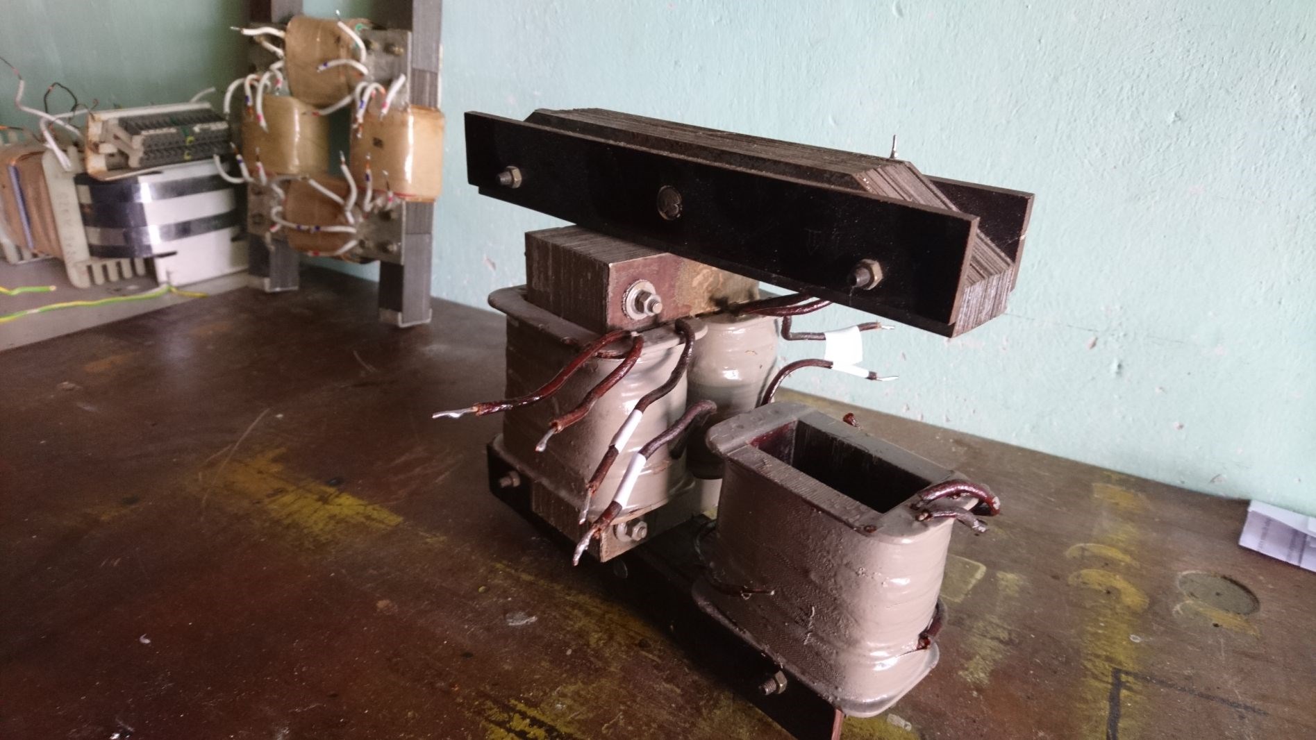
(I emphasize again here that the result will not be the point, but I will also provide data)
Since I disagree with the described operation on several points, I made changes! That doesn’t mean I’m doing it right or thinking it right. So I accept the comments.
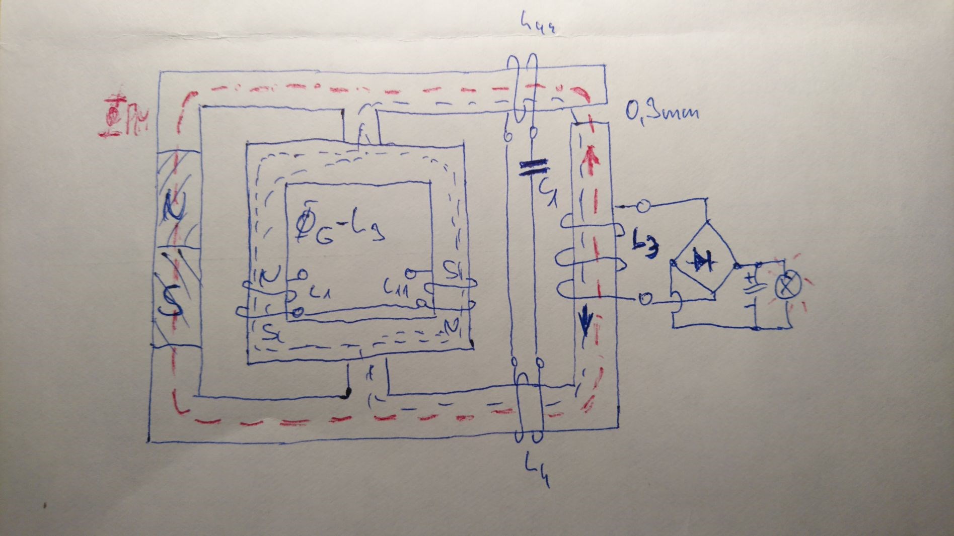
The conceptual layout of Bu.Meg can be seen here at rest:
Short description:
It can be divided into two major funds:
-excitation part (P.M. control)
-power decoupling -> resonance level
P.M. control:
- A P.M. it was placed on the edge of the machine because perhaps this is how it will turn the least P.M. flux inside the magnet. Thus, P.M. domain structure is thus damaged the least. It is advisable to use an application where the magnetization branches off in at least two places. (in the Bóday layout it is not the magnet that turns directly, but its space)
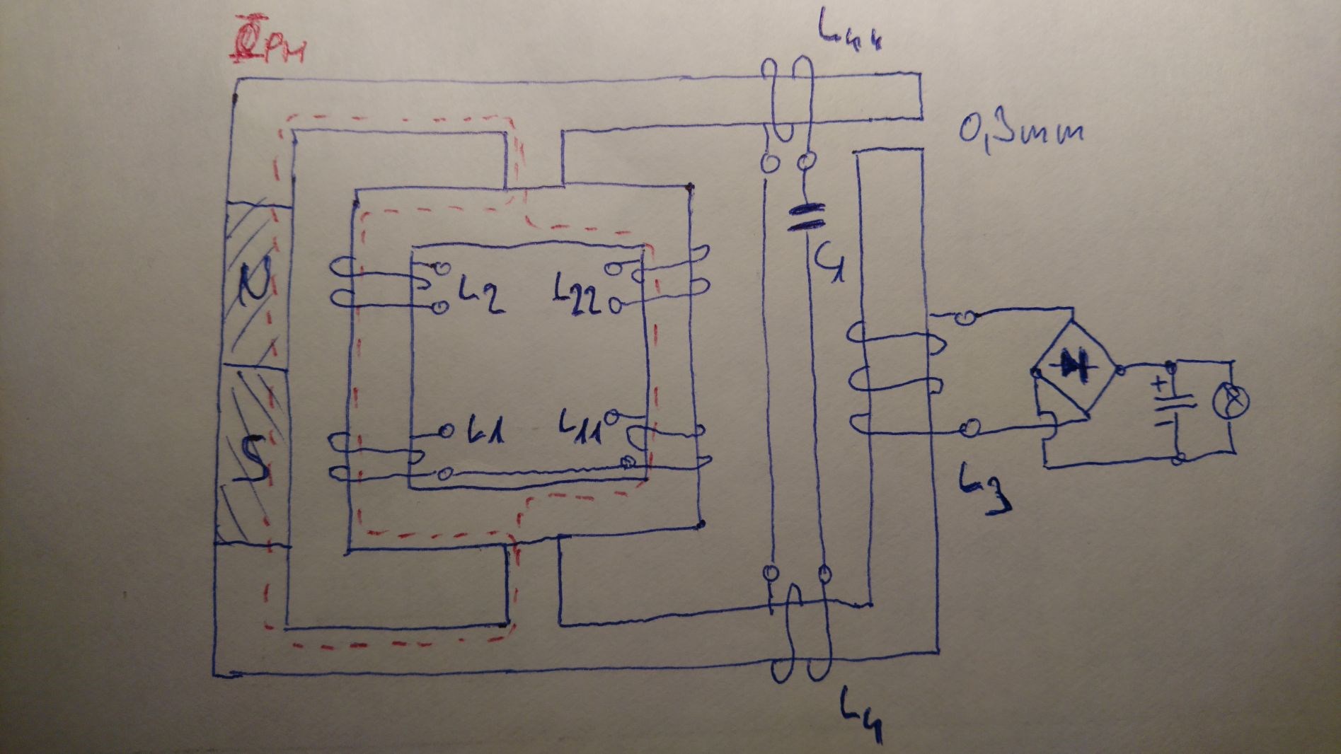
-L1-11 coils are connected in series. It has a sudden steep ascent.
Their magnetic polarity is N-S-N-S. It is controlled by an H-bridge (or it can be with two pairs of coils and SG 3525. This is shown in some pictures) therefore at each beat the P.M. you receive a repulsive pulse. Thus, the force line is forced to exit towards the L3 coil. (If P.M. is not inserted, there is no excited voltage in coil L3. No flux exits the excitation circuit)
-Air gap is critical! I tried several versions, but the best result was 0.3mm. There is no proper P.M. crossing without an air gap! (There is no air gap in T. Bearden's layout. In my opinion, however, it should. In Bóday's layout, too, I only had measurable results. Figure) 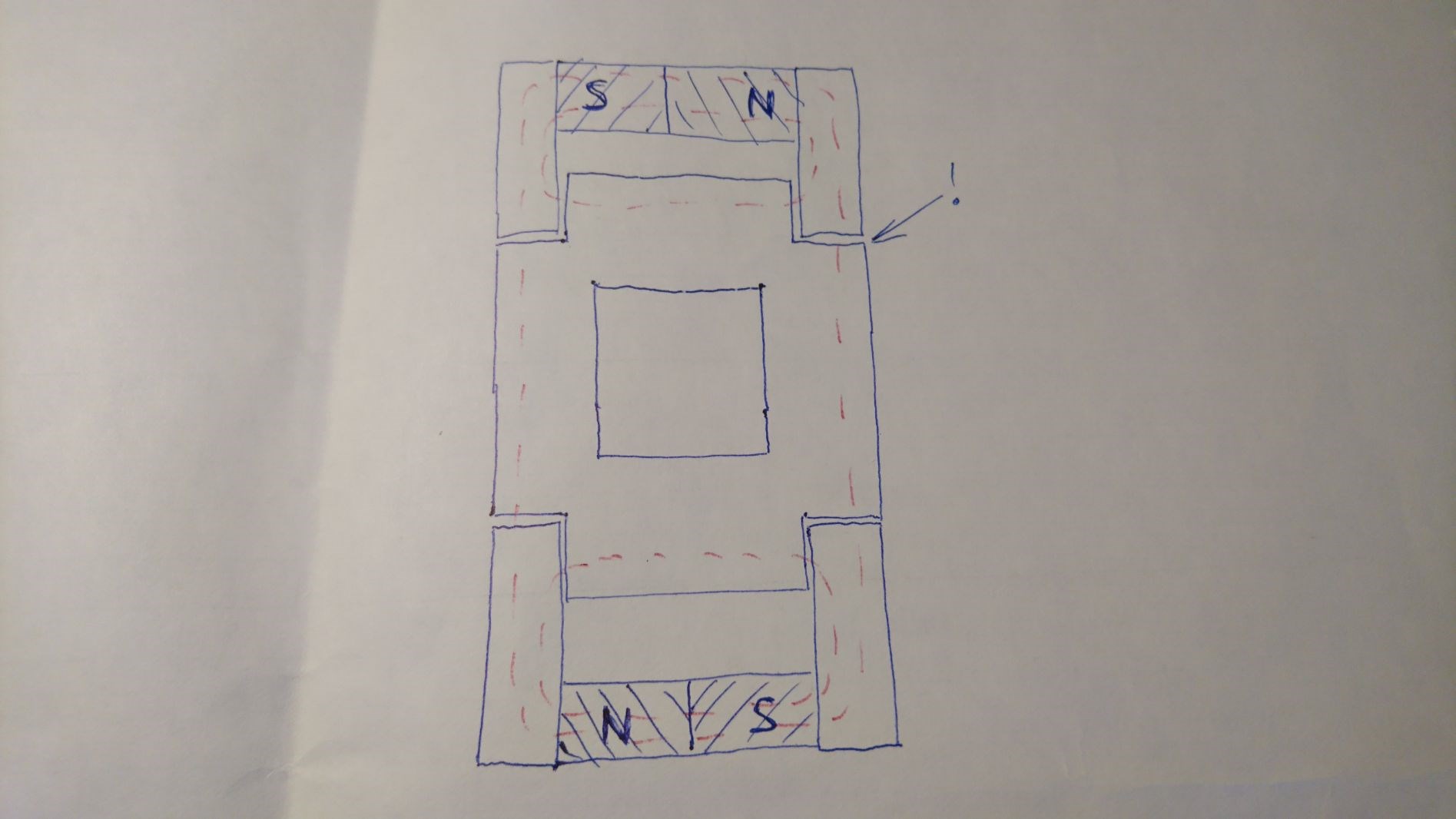
- Φpm changes twice. Therefore, if the L1-11 control is 50Hz then the voltage induced in the L3 coil will be 100Hz.
-Φpm inhibits the change in L1-11 flux (decreases inductance) therefore the added P.M. it does not bring extra energy on its own. But L3 compensates. So the combination of L2-22 and L3 gives the output energy.
-A.B. effect is presumably between L3 and L2-22 in the ideal case.
-P.M. and the way the iron material and its flux are closed. Figure.
Power coupling:
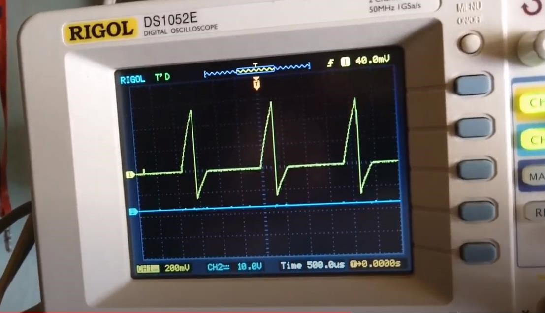
- A P.M. it only excites a steep rise voltage in a small area. Oscilloscope illustration.
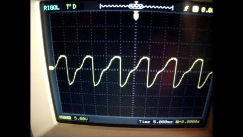
-It is reinforced by L4-44 lined coils. It results in barren power and a full sine wave.
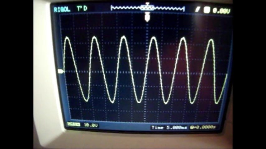
Thus, the voltage L3 depends on the voltage L4-44 as well as the magnitude of the load current.
-L3 load reduces L1-11 power consumption!
(the situation is similar if we make an asynchronous generator from an asynchronous electric motor. this is also a good game :-))
-L3 energy only in P.M. and L4-44.
L2-22 energy:
The control excitation coil is a function of voltage transmission. But it is affected by P.M. closure or L4-44. It is important to note even L3 is affected when loaded.
- The flux of the load current L3 affects (compensates) the voltage L2-22. (Figure)
This is an older recording. The multimeter measures the voltage of L2-22 (graetz and buffer capacitor). The influence of L3 is seen at 6:45-6:49.
L3 is the load output. L2-22 Charging the control excitation energy of another similar device. Thus, presumably by reaching an ideal case (if possible!) We can achieve a complete automatic device. The voltage of output L3 can be controlled with an AC / AC converter.I hope the language barriers, possible errors in the description will not be a problem for those interested.
Regards , Nagy Attila.
continue ..