Adam’s Experiments and Understanding of coils and magnetism.

  • 1.4K Views
  • Last Post 4 weeks ago
Adam posted this 18 November 2023

Hello everyone,

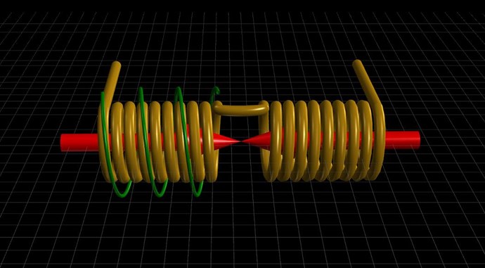
I thought I would start at the beginning by posting a video of My understanding of how Transformers, Motors, and Generators work. I think without a basic understanding of this it may be hard to understand what is going on in more complex devices. Please remember this is just how I understand what is actually happening.


The key takeaway is the core inductive reactance being variably reduced or changed due to the intensity of two magnetic fields colliding. Also, that a coil resists the change from a building and or a collapsing magnetic field.


I would like to thank Chris for taking all the time in providing free videos and all the information on this forum. The time and energy he has invested in this is INCREDIBLE!


Please comment on what you think.

Do you agree or disagree?  lol


Adam.

Order By: Standard | Newest | Votes
Chris posted this 18 November 2023

Hi Adam,

Thank You for the kind words my Friend! Welcome, we will help you reach your goals here, we are a good well rounded community that tries its best to get rid of trouble makers! We have had a lot of them!

Magnetic Fields, the Change of Magnetic Fields, and the Symmetry and Asymmetry of the arrangements is a critical aspect to this whole thing! Faradays Law is incomplete, and its got major holes!

We will help you along, but you have to put some work in to get there. You cant give up half way through, its a road that must be traveled, and many roads lead to Rome!

Best Wishes,

   Chris

Adam posted this 27 November 2023


THE TIN MAN REPLICATION


Hello,

I think it is important to go over what I think is really happening in the Tin man replication and what I have learned from it.

The information in this video I believe is very important on the understanding of how several of the bucking device’s work and will lead into the next video.


One of the most important facts is that a coil with a collapsing magnetic field can resist that change and create its own magnetic field!

That field can now do work in the form of bucking another field or extending itself further in space.

Have Fun!

Adam.

Chris posted this 28 November 2023

Hello Adam,

First up, well done its very good replication! Its good to see such due diligence here!

At Time T0, nothing is working, at T1 we see everything starting to occur, everything starts doing its thing: Input Current Ramps, Secondary Current Ramps, and Tertiary Current starts to build as the Secondary's Current creates a Voltage on the Tertiary Coil. There is a slight Delay between the Conduction in the Diodes, because the Induction between the Coils takes time.

I want to say, Floyd Sweets VTA, Vacuum Triode Amplifier, has always been my primary area of focus and research, for a long time. I learned from the data available on Floyd Sweets VTA, and a Triode is a form of Diode! Effectively a Vacuum Diode, its the same thing. So, my research is in the same area and I have been doing this since 2001. I have been sharing my research for many years now!

I left you a message, its important to get this understanding down:

+1 - Yes Tinman is right, I have asked Tinman to join us, but he does not want to join us. He and I have had a bit of a falling out. Your theory is not really right, you have too many delays in there, LED = Diode, and all Coils interact at the same time, yes they Buck, but if you look at the Vector Sum of the Magnetic Fields, you get: 1 + -1 + 1 = 1, so One Coil Opposes the Primary and one Coil Assists the Primary. 1 + -1 = 0, so you have a Vector Sum of Zero, no Net Force Reaction in One Direction. If you scope the Voltages you will see this arrangement as Tinman and I have stated! Assumptions cant explain this configuration!


Your understanding is not quite right, you're about 97% correct:


Air Cores don't Saturate, Current can only flow if a Voltage is present, and all Coils gain a Voltage to be able to conduct, so Input Coil does not Generate POCTwo's Voltage, POCOne does, and a few other things. But, well done! I am impressed! Yes to Don Smith also, its a common concept all around all Energy Machines! VTA, Don Smith, UDT, The MEG and so on, all the same basic working principle!

Tinman's understanding is 100% Spot on;


All though he did miss some important information.

You will see, if you apply this analogy, in a Graphical Form, in Partnered Output Coils:


In the Equation I gave you: 1 + -1 + 1 = 1, 1 represents a Vector and the Negative Sign represents the Sign of the Vector, direction of the Arrow in other words.

Tinman was the first with his Rotary Transformer V3.0:


Do the Math on that Video!

Imagine you are pushing your Apple Cart up a Hill, and your friend is already at the top of the Hill, you have a rope tied between your Apple Carts, and as your Friend goes down the Hill, he helps you travel Up the Hill, so you get an assistive Force, for Free, in your Configuration.


I was a bit cranky with Tinman and his Buddies, his Buddies caused a lot of trouble, a LOT of Trouble, yes I have their Names, there are a lot of outright Liars out there, they got me banned from ou.com, which ended up being a very good thing, and they stopped Tinman's progress!

We see, Newtons Laws of Motion Completed: Action, Reaction and Counter-Reaction, from Action and Reaction, describing only Symmetrical Systems! I shared this quite sometime ago now: Here September 14, 2015.


Tinman is still welcome to join us if he wishes to, but alas, I think we have had too much of a disagreement and he still does not forgive me for my part in getting this technology out to the people. Tinman has supported me in my effort in other ways:

Many have told you, what I am sharing, Works:

Many here laugh at, and mok EMJ, but the fact is , he is basically right in what he is trying to put forward.

http://overunity.com/15395/partnered-output-coils-free-energy/msg460945/#msg460945


 Everyone is looking only at the electrical output of my device,and seem to be ignoring the mechanical output that is also there.
 They also dismiss EMJ's shorted coil theory,and although he hasnt shown a working device yet,and he messed up the scope measurements,his theory is sound.

http://overunity.com/15395/partnered-output-coils-free-energy/msg453458/#msg453458


   PM

 How closely do you think this is starting to resemble EMJs partnered output coil setup?,as i am seeing some resemblance here.


 Brad

http://www.overunityresearch.com/index.php?topic=3319.msg57155#msg57155


I think it is time Grum,to answer this question once and for all.

For every action,there is an equal and opposite reaction--and then there is the counter reaction

Open the topic,and lets get ION on the scene ,as he knows his way around calorimetry setup's,and i believe this is the way to show PMs doing useful work.


Brad

http://www.overunityresearch.com/index.php?topic=3319.msg56743#msg56743


As Chris says "keep it simple"!

Ref: Captainloz


Chris has given everyone here the knowledge to be successful so you are in the right place.

Ref: Aetherholic


This is a taste of what can be achieved with the right Understanding!


We Humans have a very strange way of showing Brotherhood and Sisterhood. Either way, Tinman is 100% Correct and everyone needs to listen to Tinman's words and pay attention to them! He is Correct! He and I have given all of you nothing but Truth! Nearly 10 Years ago now!

Again, well done its very good replication! Its good to see such due diligence here! I hope others pay attention to your effort and learn from your work! Well Done!

Best Wishes,

   Chris

Adam posted this 28 November 2023

Thanks for the feedback, Chris.


I mean no disrespect to Tin man, I think his video was great, and I am very appreciative of the two of you for making videos of working devices and then explaining your understanding on how they work! I think you are the only two people I have ever seen do that. Thanks…


It would be nice to see him come back and share more of his experience’s and what he has achieved now.


In the video I focused on the primary collapsing field and POC2 holding it on because I’m thinking that the magnetic diode effect and the POC2 holding on to the primary magnetic field may be happening at the same time and it’s a good segue into the next video of collapsing field repeaters.

It is interesting how I am getting the same effect when I pull the two coils apart and the primary coil field cannot reach POC1. The process of turning off the primary and having POC2 hold on that field with no kickback to the primary and at the same time POC2 bucks POC1.


Please remember I am also learning and am trying to completely understand what is actually going on in all the various devices.


Thanks.

Adam

Chris posted this 29 November 2023

Hey Adam,

My Friend, you're most welcome, you're doing a really good job! Well done!

You are mostly right!

A Current can only flow in a Coil if there is a Voltage exists, that means, the Terminals of the Coil must have a Potential Difference, a "Generated" Voltage.

The Magnetic Field of the Primary does have two phases, a Ramp Up Phase:


and a Ramp Down Phase:


At TOn the Coil experiences di/dt, changing Current I, over Time t, which represents the very same change in Magnetic Field. Current I is analogous to the Magnetic Field B.

Every single Coil that experiences di/dt, can be used as a Source for Electromagnetic Induction. This Coil can be, Primary, Secondary, or a PCB Trace on a PCB Board, where Engineers work very hard to stop what they call Parasitic Inductance:
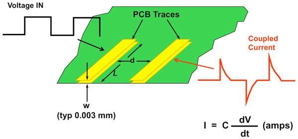
 

The Coupling of Inductive Components, gives rise to Charge Separation, via Electromagnetic Induction, which we want to focus on and take to a new level, Asymmetrical Electromagnetic Induction, well beyond the current Symmetrical Electromagnetic Induction bounds, where: Output = Input - Losses, never able to become Above Unity!

My Research leads me to believe, all of the Action Reaction and Counter-Reaction's occur simultaneously, but with slight time delays, I call this Delayed Conduction, before the DUT reaches Peak Potential.


Time = T0

Everything is static, nothing is occurring.


Time = T1

The Mosfet turns on, TOn, and the Input Coil starts ramping up in Current, the period we are interested in, is τ, Tau, the 5 Time Constants, from TOn, to reach peak Magnetic Field in Time t, after that, there is no point having the Input Mosfet On, as we are wasting Current, I2R Losses. As there is no more 'Change' in the Input Coil's Magnetic Field B, the Input Coil can not "Generate" any Voltage V.

During Time = T1, we see POCOne's Voltage going up to Peak Voltage V, which is directly linked to the Input Coils Change in Magnetic Field, via Faradays Law: E.M.F = -NδΦ/δt, because POCOne is loaded, Ohms Law states: I = V / R, and thus the Current I flowing in POCOnes Circuit will be the product of the Resistance and Impedance, and the Voltage V "Generated".

Also, during Time = T1, we have a Current building, δi/δt, in POCOne, which we calculated, which can be used as a Source, for Electromagnetic Induction to occur again, giving us the ultimate, Asymmetrical Electromagnetic Induction machine, but, only if we take advantage of this beautiful Natural Law. 

This Changing Current δΦ/δt, "Generates" a Voltage V in POCTwo, and as a result of this Loaded Circuit, we get the same situation occurring, the Current building, δΦ/δt, gives us a feedback mechanism, which in turn makes the LED Glow more brightly, and because we have an Asymmetrical System, we can draw more power from it under certain circumstances. Its an Open System, its not a Closed System, and therefore does not have to abide by Conservation of Energy Law.

During this Time T = T1, we have a Slapping together of the Partnered Output Coils, they are Bucking each other with all the Magnetomotive Force they can, Peak Potential is reached:
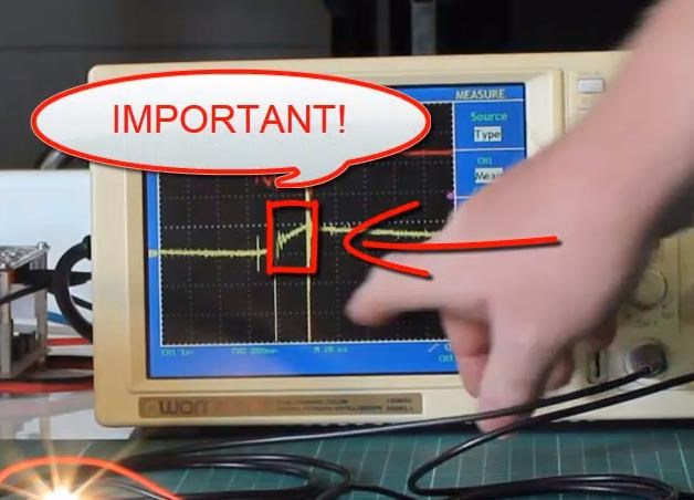
 

All of this happens where I have marked Important, this is one Time Slice.


Time = T2

The Input Coil's Mosfet is turned off, TOff, and the Current to the Input Coil no longer flows from the Source to the Input Coil. However, this does not mean no Current Flows, we do have Current Flowing:

Here is an example:
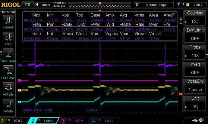
 

Where:

  • Purple Trace is the Math, showing Positive and Negative Power.
  • Pink Trace is the Gate Signal to the Mosfet.
  • Yellow is the Input Voltage.
  • Teal Trace is the Input Current, both Positive and Negative.


I must apologise, I have better examples of this, but do not wish to confuse everyone. This example is sufficient to show what I am talking about.
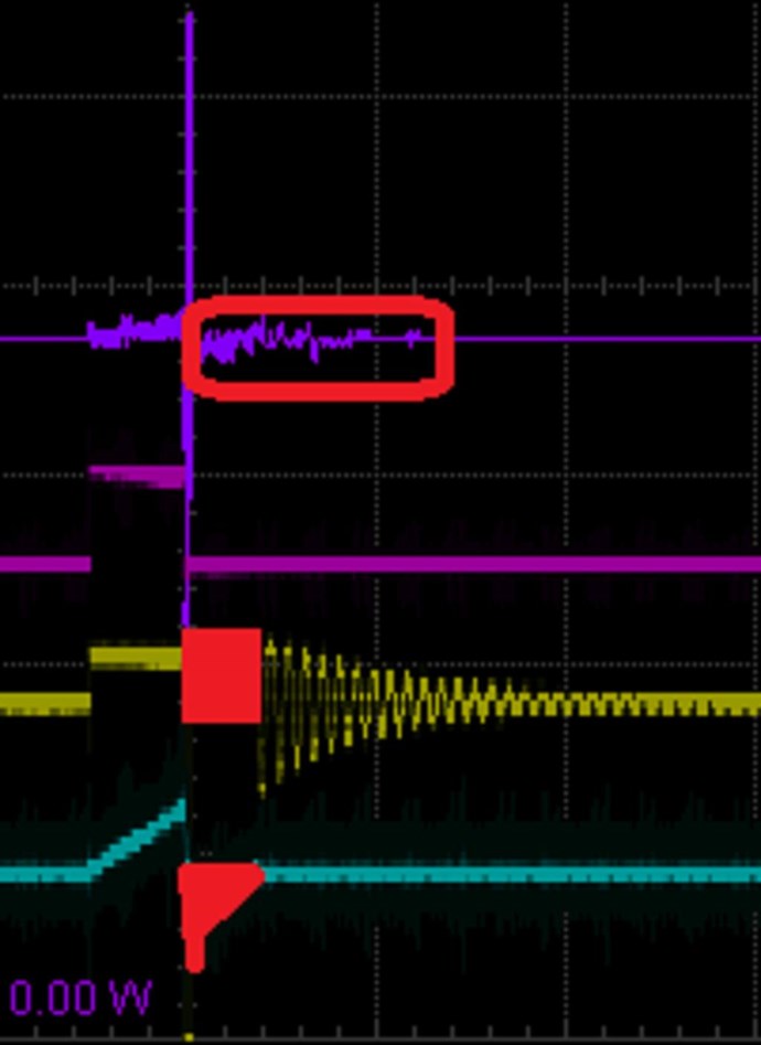
 

Again, marked in Red, Positive Voltage and Negative Current, you have Negative Power. Not Negative Energy, Negative Power, I hope people do not confuse this as I believe people have in the past.

I hope this helps others when doing experiments, knowing what to look for is very important!

Remember: This is the very reason you can NOT Use RMS Measurements on the Input! See Measurements Thread and see the above Figures:

  • Average: 95.7 mW
  • RMS: 1.28 W


A Huge error here! 1.28 - 0.095 = 1.185 Watts. 13.474 times!


At TOff, we have Current going back to the Input Power Source! Because of our Asymmetrical Configuration, or our DUT, the used Power is a small fraction of the actual Active Power! We have a large Reactive Component here, most of the Input Power goes back to the Input Power Source! Its Reactive, Ping Pong Power!

Does this ring a Bell?
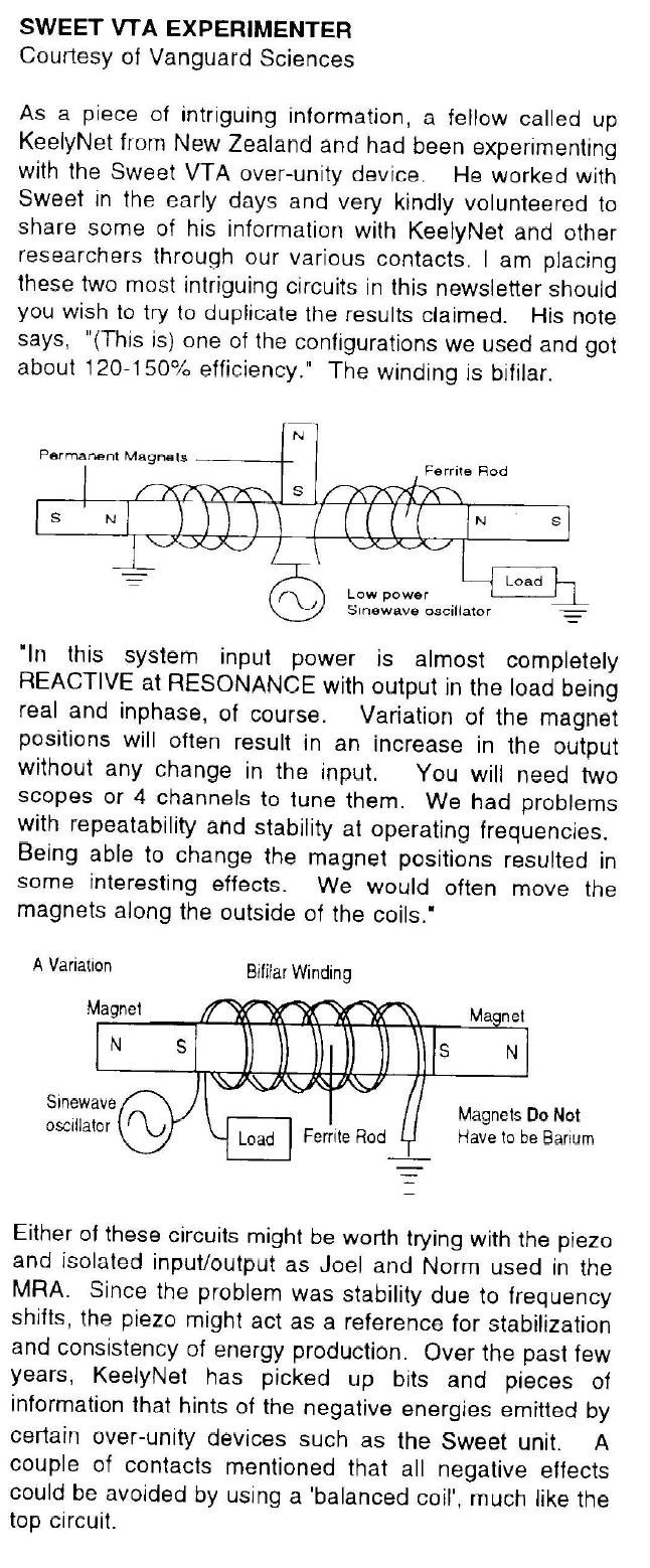
 

REACTIVE at RESONANCE... I hope all readers can see where I am heading?

At the same Time, our Partnered Output Coils are Bucking Each Other, so the Fields here are being supported, held High, a method described, but not clear, by Floyd Sweet:

They are now able to simply support mass, as demonstrated with the transformer steel illustration.


Does a Magnetic Field have Mass?

The Magnetic Fields slowly reduce in Strength H, over Time t, as the I2R Losses and the Load, consume power.
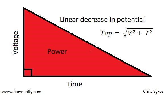
 

Note, the Time Constants are not the same! Each Time segment is different, because different things are occurring during these phases.

Forgive my ramblings, I only aim to help.

Best Wishes,

   Chris

Chris posted this 29 November 2023

Hey Adam,

I was thinking, observing the Polarity of the Diodes, that gives you a clue as to what I said above. The Right Hand Grip Rule and the 0.5 Volt Break Over Voltage on the Diodes, means, before the Diodes can Conduct, a Voltage of 0.5 Volts or so, must be applied across the Diodes.

You will see this by scoping the LED / Diodes, while in operation.

Best Wishes,

   Chris
 

  • Liked by
  • Augenblick
  • Plasmonic
Adam posted this 30 November 2023

Yes, I was thinking that also. lol

Adam

  • Liked by
  • Augenblick
  • Plasmonic
Adam posted this 30 November 2023

Hello,

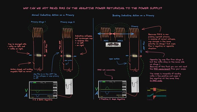
I tried to make a visual representation of the above conversation about negative power flowing back to the power supply and the RMS reading.


Please let me know if I can change something or if something looks inaccurate.

Thanks.

Adam.

  • Liked by
  • Augenblick
  • Chris
Chris posted this 01 December 2023

My Friends,

Adam is absolutely correct!

You can NOT read RMS Values on your DC Input! If you do, you are instantly Wrong and your measurements will not be accepted as accurate! On the Input, with a DC Source, you MUST Read Mean or Average Values!

Those that argue differently, and there are some, the trolls we have made obsolete, for example, very simply do not know how to correctly Measure Power! Plain and simple, they do NOT know what they are doing!

Understanding how a DC Source works, and understanding how a Non-Linear Load works, will prove to yourself, why RMS Values can not be used, so Adam is absolutely correct and all here should know this, we have many examples and videos showing this.

Adam, you should be very proud, you have come a long way in a very short time! I am impressed! Thank You for showing how simple this can be if one takes the time to gain an initial understanding!

Best Wishes,

   Chris
  • Liked by
  • Augenblick
Adam posted this 01 December 2023

Hello,

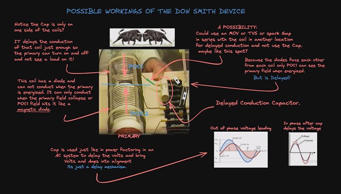
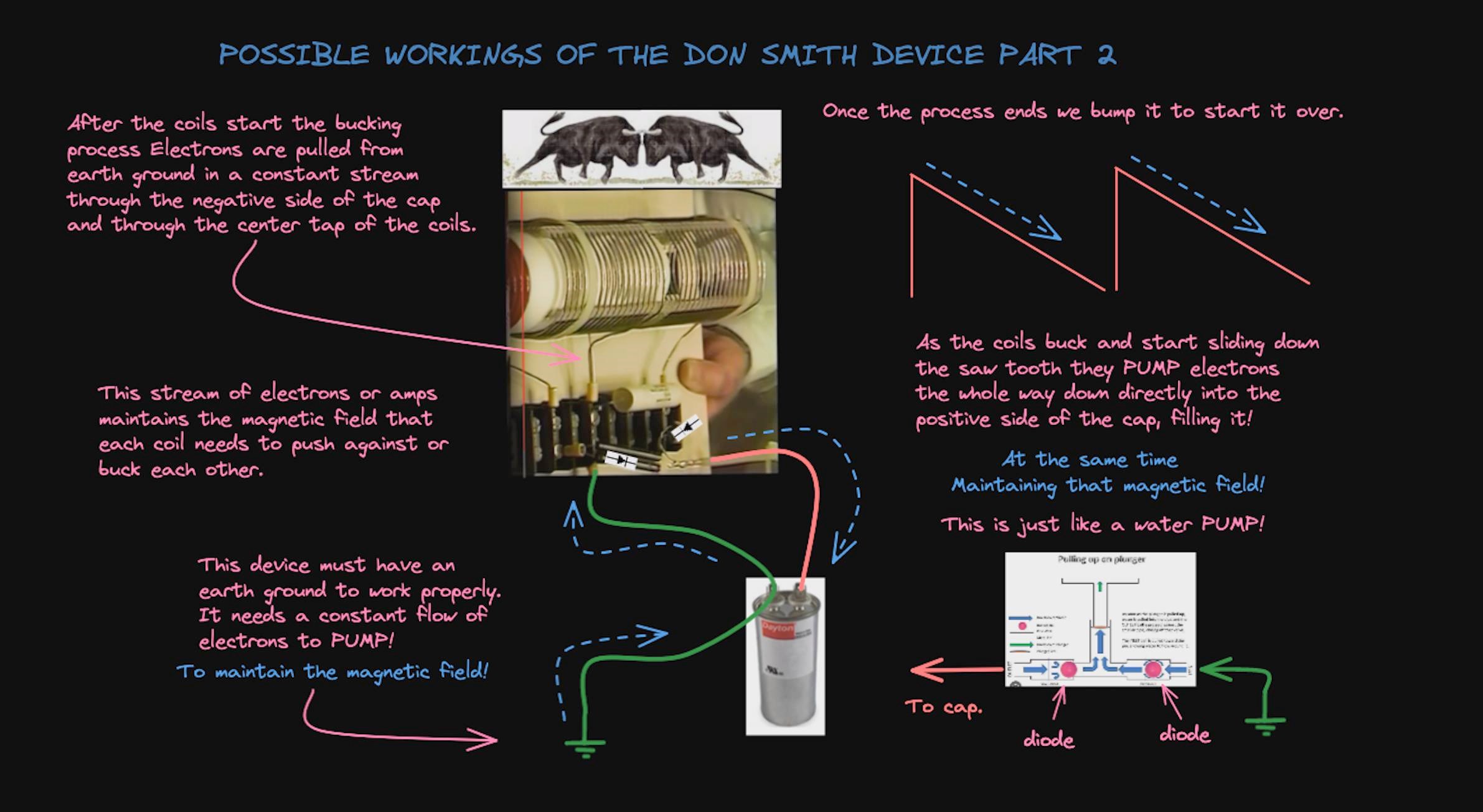
This is my idea of the possible workings of the Don Smith device.

I thought I should touch on this after I compared it to Tin man in the video Tin man Replication.


Have Fun

Adam.

  • Liked by
  • Chris
  • Augenblick
Adam posted this 01 December 2023

Chris,

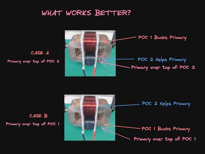
Looking at the picture of one of your devices, what works better in your opinion?

I am able to get the saw tooth wave in either Case.


Case A – Primary over POC 2

Case B – Primary over POC 1


Thanks

Adam.

Chris posted this 01 December 2023

Hey Adam,

Again, excellent work, thanks for sharing!

To answer your question, we must ask another question: "What coupling configuration, maximizes the Energy sent back to the Input Source?"

How is the Energy Sent back? What sort of Coupling is required to send Energy back to the Source?

Running experiments on the bench is the best way to prove to yourself, what works and what does not, but you have bought up an important question, the answer is very simple, flipping the diodes is all it takes.

Please Note: Don Smith was 100% Correct in what he shared with the community! I believe it is very important to understand, all of us have Limitations in our personal Knowledge at any specific time. Did Don Smith's devices take full advantage of the Parameters that Magnetics' allows for? For example, instead of using a Brute Force Approach, can we be a little smarter in the approach, and bring about DUT Operation with a less complicated approach? What would you change to make Dom Smiths machines easier to experiment with? The answers will surprise you!

Best Wishes,

   Chris
  • Liked by
  • Augenblick
  • Plasmonic
Adam posted this 01 December 2023

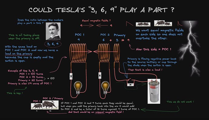
Must be CASE 2 over the one that bucks it.


That brings me to another idea.

That is the two coils being ( POC 2 and Primary) should be equal to the opposing coil POC 1.

This is based only on devices that have a path from the primary back to the cap once the switch is opened.

What are your thoughts?


Thanks

Adam.

Chris posted this 02 December 2023

Hi Adam,

I don't agree with that, sorry.

Partnered Output Coils by themselves, require Symmetry and Matching of Magnitudes of Magnetic Fields, therefore Current through Turns or Ampere Turns, AT, must be as close as possible to Equal, this is Magnetic Resonance, Equal in Magnitude but opposite in Direction.

The Closer to Magnetic Resonance you are, the less Input Current is used.

Worth having a think about the Input Coil and what makes the Input Coil Change its internal impedance under certain conditions! All Coils change their Internal Impedance at different stages during the Cycle. We see a Non-Linear Impedance, or a Non-Linear Inductance occur.

Best Wishes,

   Chris
  • Liked by
  • Augenblick
  • strape
Adam posted this 02 December 2023

No problem, Chris

Thanks for the input I’m just throwing out some ideas and trying to have more understanding before going back to the bench.

I think this also helps others think about what’s going on too.


Adam.

Adam posted this 02 December 2023

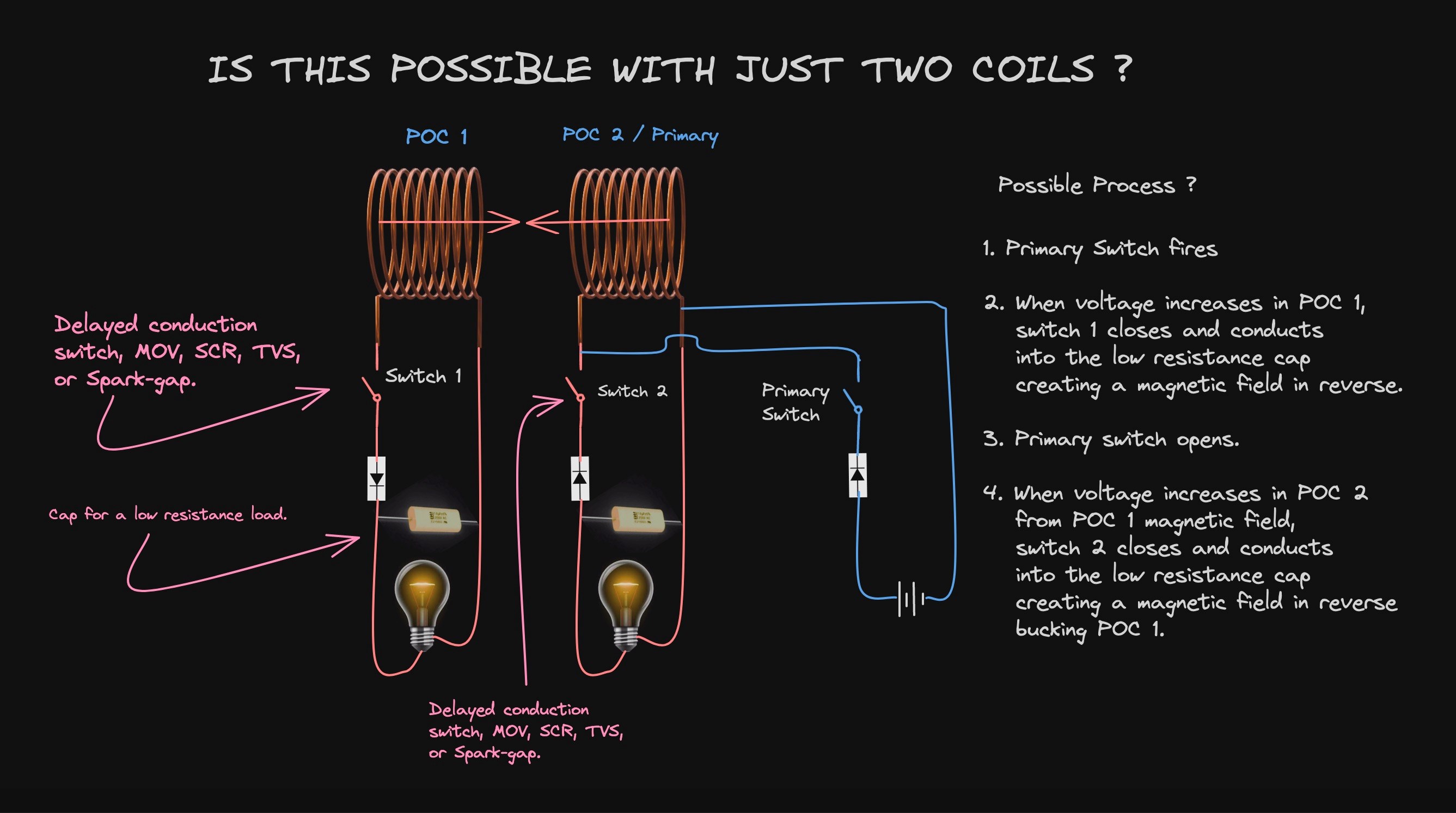
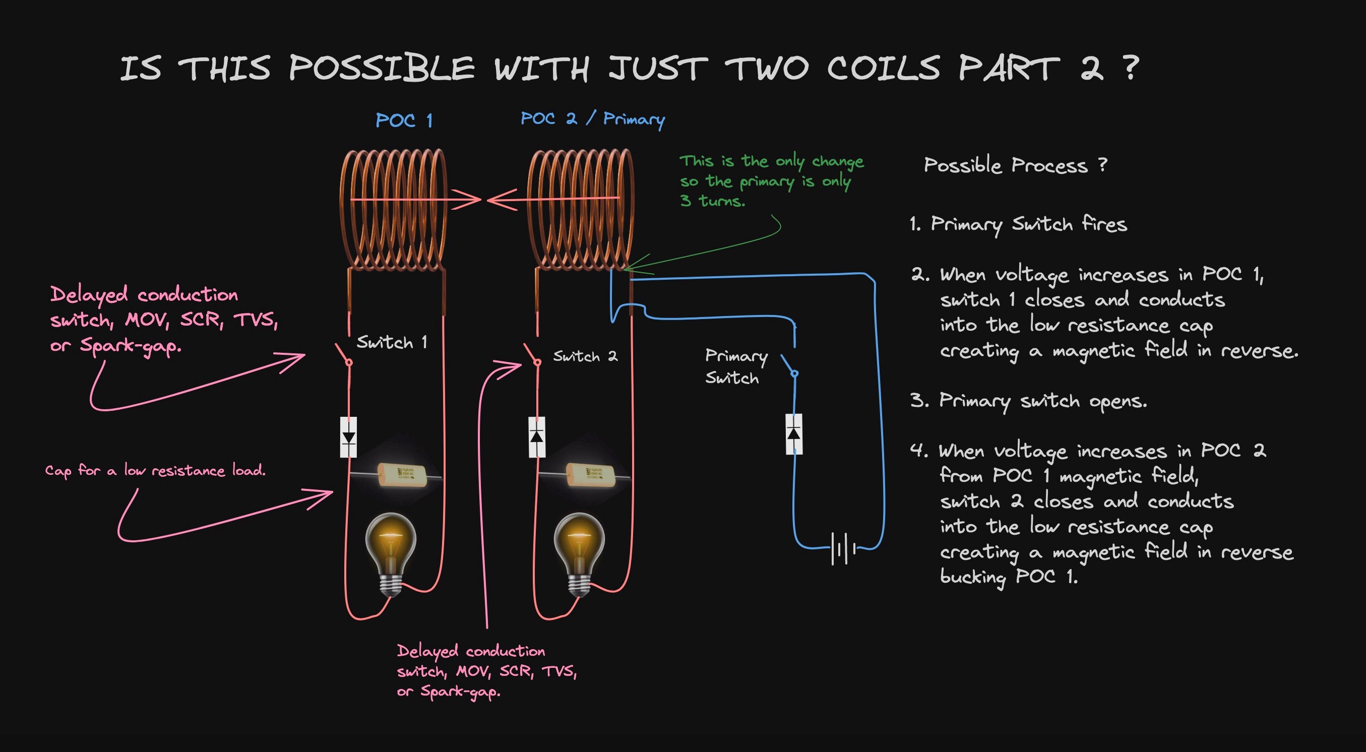
Hello

One more possibility to discuss.

Using only two coils instead of three for the same interaction?


Thoughts?

Adam.

Chris posted this 02 December 2023

Hi Adam,

Yes, we have also shown this, one example of this experiment is: YoElMiCrO's Ferro-Magnetic Resonance

Delta ΦB, the Magnetic Field changing in Time t, is the Key, this "Generates" a Voltage in Conductors in proximity. This is Faradays Law, however Faradays Law is Incomplete and simply by completing Faraday's Law, adding the all important Asymmetrical Component to an existing, entirely Symmetrical  Arrangement we insist on today.

Where Symmetrical Arrangement would be: Input Coil, Output Coil, Transforming Electrical Energy: Output = Input - Losses.

An Asymmetrical Arrangement is: Input Coil, Output Coil, and another Output Coil, Electrical Energy is "Generated" E.G: Output ≠ Input - Losses.


Todays Scientific Understanding of Faradays Law is antiquated and blatantly Incomplete! Every experiment we show, proves, without a doubt, we are at the beginning if a new subject in Science. Asymmetrical Electromagnetic Induction is a door wide open, we have opened this Door, and we are World leaders in a Field that begs for brand new, fascinating, and very beneficial, Invention and utility.

Secondary Coil Geometry is an Important aspect, as both Secondary Coils, need to "Generate" enough Voltage to be Useful. 

Because we are smart and we have incorporated Asymmetrical Arrangement, we have a Feedforward and Feedback component, that "Generates" more Voltage, and Pumps more Current, under more Load, so we have a very smart intelligent operation, from a few simple Coils and Magnetic Field interactions:


We have the Answers, we only need to get others working and learning the very simple, very cheap technology. 

Best Wishes,

   Chris

ZeUs21 posted this 03 December 2023

No problem, Chris

Thanks for the input I’m just throwing out some ideas and trying to have more understanding before going back to the bench.

I think this also helps others think about what’s going on too.


Adam.


Thank you Adam, those drawings you do help me understand immensely. As a visual learner all the visual material Chris and you guys put out have helped greatly. Dyslexia is a bit*h when it comes to words lol.

Just wanted to say thank you.

Adam posted this 03 December 2023

Thank you for the kind words,

I have the same visual learner experience that you have. lol

More is on the way!


Adam.

Adam posted this 04 December 2023

Hello,

Let’s take a look at repeater coils.

What happens with the Tin man replication when you flip one of the diodes?


Have Fun

Adam

  • Liked by
  • Amin
  • Augenblick
Chris posted this 04 December 2023

Hey Adam,

No, I disagree with your amination and this approach.

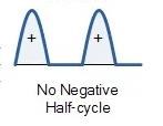
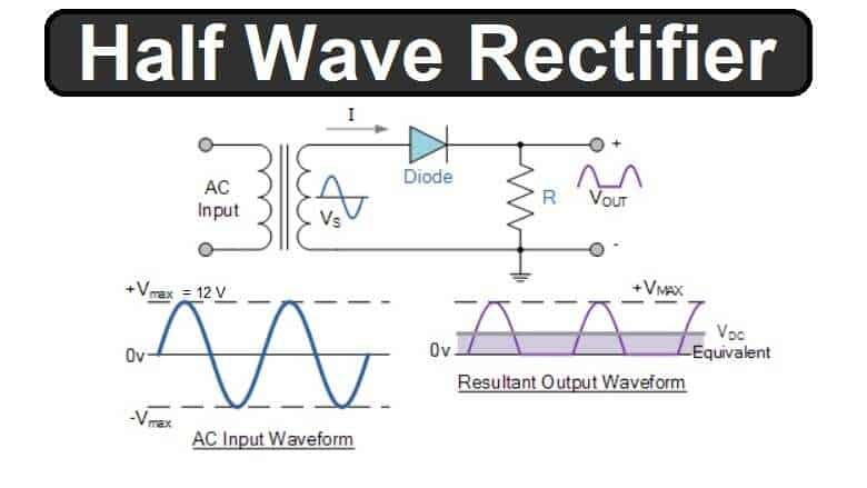
Half wave AC rectification shows where you are going wrong:


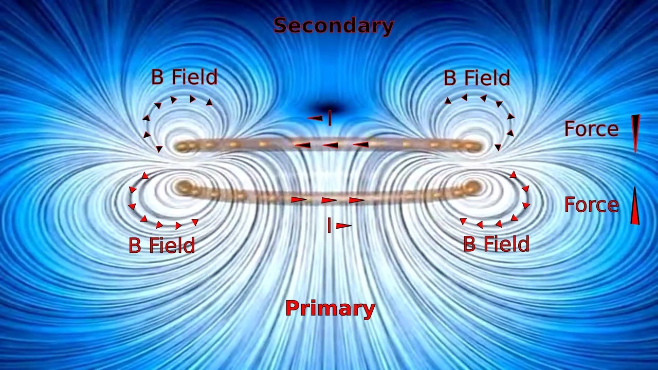
The following Simulations are from the MIT Courseware, in Electrodynamics. It is very easy to prove this sim correct on the bench!

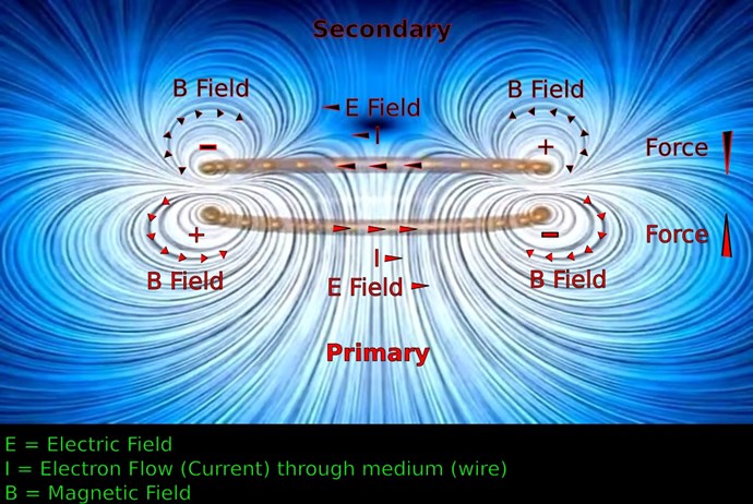
Primary is on the Bottom Coil, Secondary is on the Top Coil, thus the Conventional Transformer Modeling Standard.


The Magnetisation Phase:


The De-Magnetisation Phase:


Your approach and your timing is wrong. Always Lenz's Law is Opposite. There is always a Negative Magnetic Field Effect to the Source Magnetic Field Change.

I want to help you further understand these effects, because they are very important to gain a full and total overall operation.

NOTE: All Coils have I2R Losses.

Best Wishes,

   Chris

  • Liked by
  • Augenblick
ZeUs21 posted this 04 December 2023

Primary-Secondary


Given the animation, would these labels be correct? The Primary pretty much induces all components to be in opposition.

  • Liked by
  • Chris
  • Augenblick
Chris posted this 04 December 2023

Hey ZeUs21,

Absolutely spot on My Friend!

With the combination of Adam's work and your work, we have 100% solid understanding of these processes! Of course, the Area Above and the Area Below the Zero Graticule Line is just a Phase Area and the Voltage "Generated" is a result of the Current Changing in Time t. Primary Current is 90 Degrees leading the Secondary Voltage and the Secondary Current is 90 Degrees lagging the Secondary Voltage, thus, Primary and Secondary Currents are 180 Degrees out of Phase. Give or take... You can see these facts in my series: Chris Non-Inductive Coil Experiment. I have done videos showing you this!

Well done all!

Best Wishes,

   Chris

  • Liked by
  • ZeUs21
  • Augenblick
Adam posted this 05 December 2023

Hello Chris,

Let’s see if we can figure this out.

I think what you are saying is every action has an opposite reaction Correct?

Meaning when the primary powers on and creates a magnetic field that the coil 1 in this case will create a reaction bucking the primary?

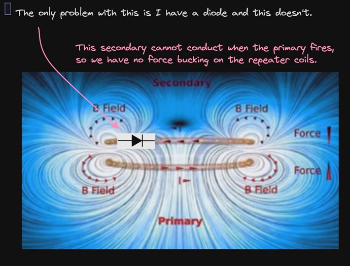
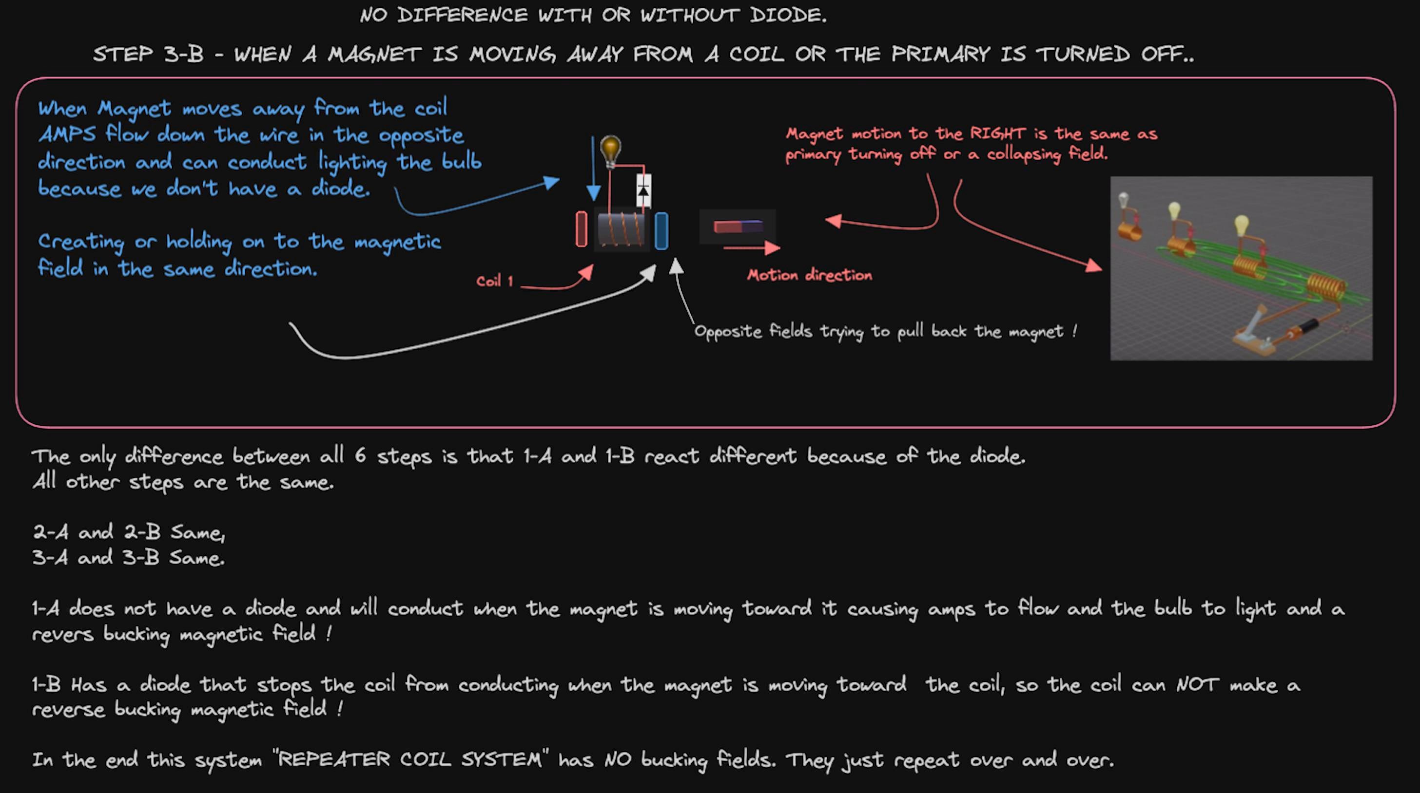
The system I am showing cannot buck the primary due to the diode.

I understand that all the other systems buck.

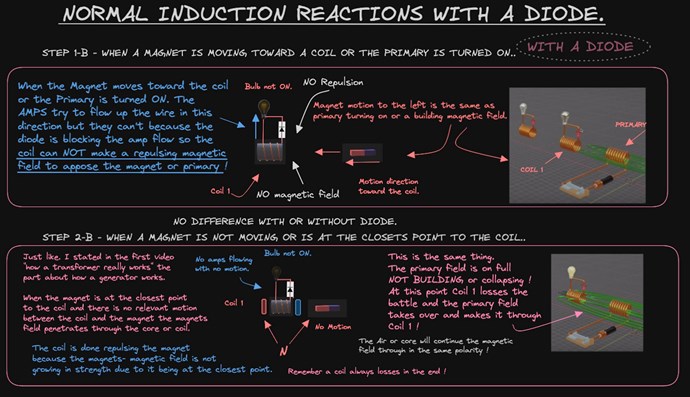
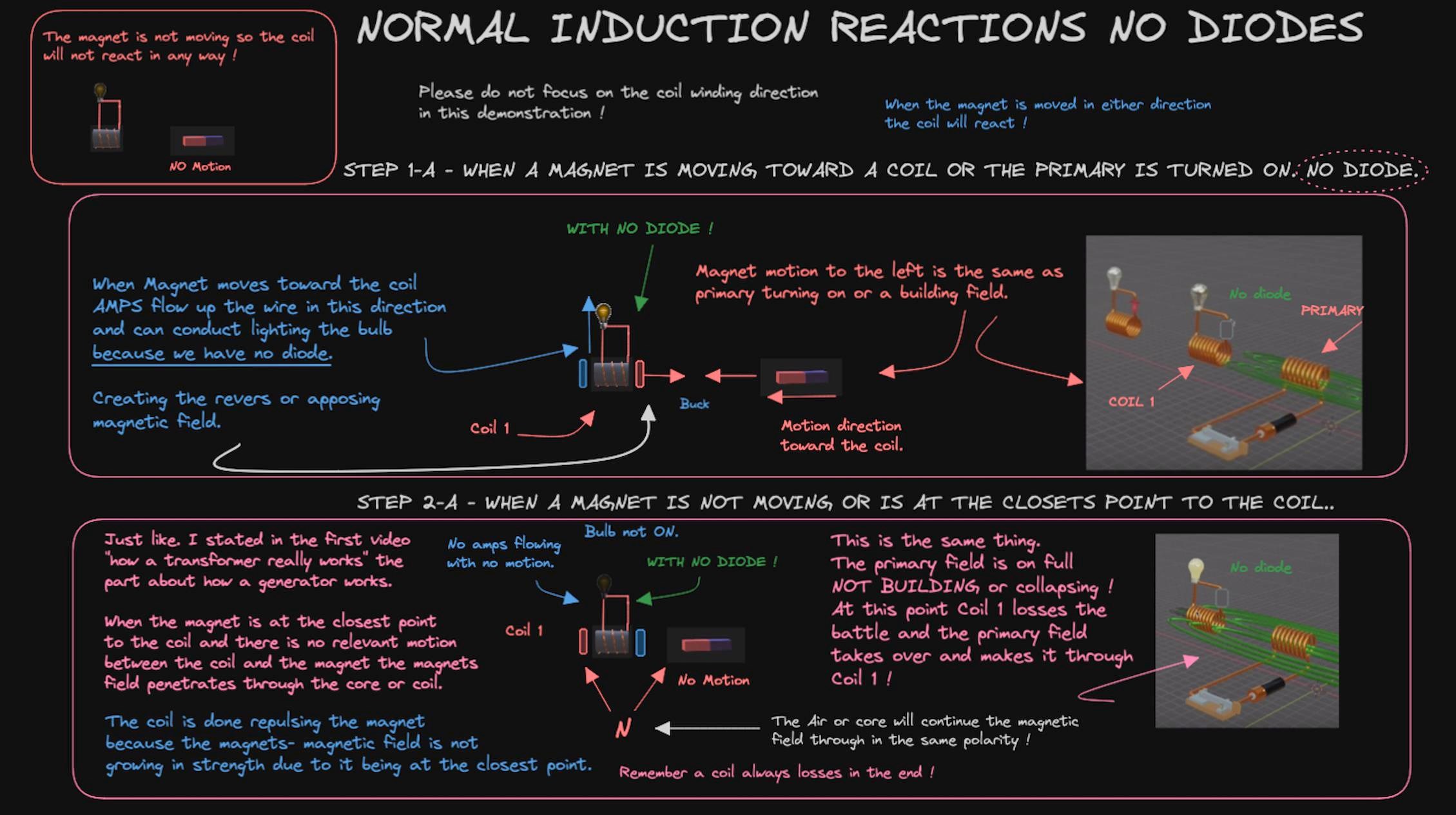
Take a look at the normal induction Step 1, 2, 3.

Step 1 Primary turns on.

Step 2 Primary is totally on.

Step 3 Primary turns off.


I understand that all the other systems buck.

I agree, that is what normally happens but I have a diode in the same direction on all the coils. Because of that diode coil 1 cannot conduct when the primary is powering up and pushing its magnetic field through coil 1. They can never buck!


Just like on the other systems you show when the primary fires only one of the two POCs will buck it because of the direction of the diodes. The other coil cannot conduct from the primary field. Instead it conducts from POC 1s field.

Have a look at the same thing with a diode.

Coil 1 can only conduct when the primary magnetic field has an inductive collapse, the current in coil 1 will then reverse and can make it back through the diode. It will then conduct through the bulb trying to hold the field on in the same direction then extending the field to the next coil.


I understand that when all the repeater coils are interacting with each other the primary has to be set to a particular frequency for resonance. I will show that, but that is not from bucking in this device.


With regards to this:    NOTE: All Coils have I2R Losses.

I think you are saying that each coil has a small loss due to the wire resistance?

If that is what you mean then I agree, each bulb would get dimmer and dimmer as you go down the line as each coil would have a smaller field. I left that for people to figure out if they decide to do the experiment.


This is my understanding at this point.

What do you think?

Thanks

Adam.


  • Liked by
  • Augenblick
ZeUs21 posted this 05 December 2023

Would this be correct then?
(Trying to create a comprehensive visual view of all components)

Some info gathered from this video

Antenna Fundamentals - Wave Propagation

B Field is referred to as the H Field in the video?


Adam:

I think I understand what you are saying. It is my limited understanding that, if you have a diode on the inductor and it is subjected to a magnetic field (B Field) from primary. It will only react if electron flow is allowed. If not, due to the diode. It remains inert and is only surrounded/saturated by the primary B Field. In your case it will only react if the Primary were to collapse/reverse (flipping its components). It would then induce electron flow in the secondary (allowed by the diode) and therefore all other components.

I am very confused atm lol, I am barely at the stage of understanding just the components in the Primary and their interactions. Let alone their interactions with a secondary.


Cheers

  • Liked by
  • Augenblick
Adam posted this 05 December 2023

Yes, I think you just told me exactly what I stated !


When primary powers on the diode stops the secondary from conducting. But when the primary turns off the inductive collapse flips the voltage and amps flow in the secondary.

It tries to hold the primary field on in the same direction, no bucking.

Look at 2-A and 2-B on my picture.


When the primary field is on full it will overtake the secondary coil and flip the core before the primary ever turns off. Then when the primary turns off the secondary tries to hold the already flipped field on.


Just like a magnet going by a coil as the magnet moves toward the coil the coil repulses the magnet. But when the magnet is in line with the coil it overtakes it and flips the core before the magnet ever starts to move away. It happens in an instant! Now we have a North magnet facing a South core and when it tries to move away the coil tries to maintain the field that is already in the core “South” and that tries to hold the North from leaving.


I think your picture is not correct, the forces are attracted to each other South to North not bucking. That is when the primary turns off or the magnet moves away.

When the primary turns on the secondary has no magnetic field of its own because of the diode.


Just remember this is not the bucking coil machines, bucking coil machines are much more important !


I only showed this so people could see what would happen if you flipped over one diode on the Tin man replication.


Thanks.

Adam

  • Liked by
  • Augenblick
Adam posted this 05 December 2023

Chris,

That’s okay this is just what I found with my own experiments. Anyone can try this it’s very easy, and see what kind of things they find out.

Maybe we can talk about this for a few more posts and then just put it to bed.

We only have 3 pictures to go through 1-B, 2-B, 3-B

If we go step by step so I can understand what you are saying starting with 1-B picture.


The North magnet moving into the coil or the Primary turning on it’s the same thing, right?


At this point the secondary coil cannot conduct because of the diode. So, the secondary cannot make its own field and repulse the primary?


No bucking at this point?


Thanks.

Adam.

  • Liked by
  • Augenblick
Chris posted this 05 December 2023

Hi Adam,

I understand what you're saying, still the answer is no. It is confusing and unnecessary to introduce something that is not relevant and not useful! I really don't like confusing people!

Secondary Diode Polarity vs Input Coil Current Polarity, is important to understand properly!

In this experiment:


The only reason you are getting LED Light with the polarity you explain, is because the polarity of the Input Coil flips for a short time, thus the Transients in the Input Coil during the switching process can be very negative. Still, the Magnetic Field is "Generating" a Voltage on the Secondary, only in the way you're not yet accounted for.

Its important to understand that Faradays Law does actually work, that's it is merely incomplete.

I am sure you understand, its very important we do not confuse others in this simple situation by introducing something that is clearly misunderstood. If I may recommend you further study Faradays Law and make sure you understand it 100% before continuing.

No Current can flow if there is no Voltage present, and "Generating" a Voltage requires Charge to be Separated. The Separation of Charge requires the Separation of Free Charges to the Terminals, Positive to one Terminal and Negative to the other, thus the term a Potential Difference. This is a Difference of Charge.


Then a Current can flow between the Positive and Negative Charge that has been Separated.

I am sure you can see the importance of understanding.

These very simple experiments and very easy to prove what I have tried to explain is correct and true.

Best Wishes,

   Chris
  • Liked by
  • Augenblick
Adam posted this 05 December 2023

Hi Chris,

Okay then lets just move on to the bucking coils.

Thanks.

Adam

  • Liked by
  • Augenblick
Chris posted this 05 December 2023

Hi Adam,

Okay then lets just move on to the bucking coils.


All Coils Buck, the Nature of Electromagnetic Induction is of a Bucking Nature.


I tried to show you this before, a pure sinusoidal waveform with no Negative Going Input, is Rectified, only in the Positive, this is Electromagnetic Induction!

This is the standard, and once you properly understand the setup you have shown, you will see that its the Input Coil Polarity changing between Positive and then Negative via switching Transients, that is your Source, its the Switching Transients that light your LED's, the polarity of the coil may appear to be Aiding, not Bucking, but I can assure you, if you investigate further, scoping the In vs Out, then you will see what I have said is true.

There is no Electromagnetic Induction without Lenz's Law, there is only Asymmetrical and Symmetrical Electromagnetic Induction, which uses Lenz's Law to Pump Current.

Please scope the In vs Out and you will see what I mean.

Best Wishes,

   Chris
  • Liked by
  • Augenblick
Chris posted this 05 December 2023

My Friends,

A simple experiment to prove this fact, that the nature of Faradays Law always being Negative, always Bucking the Source, is not only apparent in the Equation but when one gets on the bench and does an experiment to prove it,

Take a Primary and Secondary Coil.

Dump a Capacitor into the Coil of say 1000uF and make sure the primary Coil has no Negative going waveform, get rid of all transients and any back E.M.F or inductive collapse the coil would naturally have! The Input Pulse would look like:


Depending on your wiring, your Secondary can only be exposed to a:

  • North Pole growing and decaying in magnitude
  • South Pole growing and decaying in magnitude


At all times during the cycle, as long as you follow the experiment properly, you will see Electromagnetic Induction in one direction only! The other direction will have Zero Voltage "Generated" simply because there is no source magnetic field that works on the secondary coil to separate the charges! This means, as Lenz's Law states, there is only ever a Secondary Bucking Component to any Primary Change in Magnetic Field! Always! This is always true!

A Diode will only Rectify the Generated E.M.F in one direction, and the Rectified E.M.F is always the Negative of the Source Waveform, bucking the Primary Waveform.

Now watch on your scope, the secondary coil vs the primary coil. You will see, what I have said is true.

Its very easy to see, there is Electromagnetic Induction in only one direction!

I apologise, but Adam is seeing Primary Negative going Transients, that are still bucking his source, on his LED's. I only ever want to be clear and give the best correct information, so I apologise for being unaccepting of Adam's understanding, I believe Adam will see this when he spends more time and correct this when he can.

Please NOTE: A Coil with a Diode in the opposite Direction, can have an E.M.F but the Source will not be the primary Coil, it must have another Source! This is very important to Understand, for the reasons I have pointed out in this and prior posts.

Tinman has shown all of this in his experiment also, as have I. Its very easy to understand when one does the study.

Best Wishes,

   Chris

  • Liked by
  • Augenblick
Adam posted this 06 December 2023

Hi Chris and all,

Please remember that I titled this thread:


Adam’s Experiments and Understanding of coils and magnetism.


Not anyone else Experiments and Understanding this is my understanding. That’s all, right or wrong…


I did not start this thread to buck lol or start arguing that people are wrong in there thinking or am trying to change anyone’s minds or progress.


I am not  quote: “Perhaps some use this as a new Tactic, to try to confuse others, and thus stop Progress in the Community? I don't know.”


I am not a plant or trying to stop progress or trying to confuse others. Just the opposite!


I know those people do exist and are some of the old people I and everyone has been watching for a very long time. I think they are trying to steer people down the wrong path and it is upsetting to me.


What I am, is just a nice person that I thought I would try and share my experiences correct or not correct and just trying to show the road I took to get to the point I’m at now. Bucking coils or bucking magnetic fields which is where the real power is! Just as Chris has been showing for 10 or more years.


If Chris allows, I will continue to show my progress with the bucking coils on several different devices and also try to figure out  and try to use theory on how other device work.

I am only trying to help and show what I have done. I am not as advanced as Chris and am still learning how some of the devices work.


I will also need help.


I will try to answer any questions I can about the work I have done.


Chris, I think I am on the same page as you. Please see my post on your thread:

Polarity of a Generated E.M.F.

I believe all the same things you do!

Sometimes I word things slightly different as I am NOT conventionally trained and my understanding of some things may be slightly off or varied from yours.


Thank you for putting out all the info you have, I would not be as far as I am without it!

I am NOT trying to create a headbutting with anyone as I am learning too.


I hope this helps to clear some things up.


Thanks

Adam.

  • Liked by
  • Chris
  • Augenblick
Chris posted this 06 December 2023

Hey Adam,

My Friend, with all due respect, I am only trying to help you understand where the E.M.F is coming from.

Its ok for us to agree to disagree anyway. We are grown adults, we don't have to agree on everything. I only wanted to point out, that I disagreed with what you said and try to help in the understanding.

Best Wishes,

   Chris
 

  • Liked by
  • Augenblick
  • Adam
Adam posted this 11 December 2023

Hello,

I am going to make an attempt to simplify the Bucking coils process. Lol


I have made a short video and I know some of the processes may be slightly off.

This is just so we can get our heads wrapped around what is going on in the simplest way.


Action – Reaction – Counter Reaction.

Thanks

Adam.

Adam posted this 11 December 2023

Hello,

I made a short video showing what happens when you reduce the resistance in different ways.

Resistance in the Load, Wires, and Grounding.


I like to reduce all of this at the same time to make the machine the most efficient and to get the hardest Buck!

From what I can tell these three things are key!


Thanks

Adam.

Adam posted this 11 December 2023

Hello,

This is the next device !


Have fun !

Adam.

Adam posted this 12 December 2023

Transformer Test Rig# 1

Hello,

This is what I’m calling:

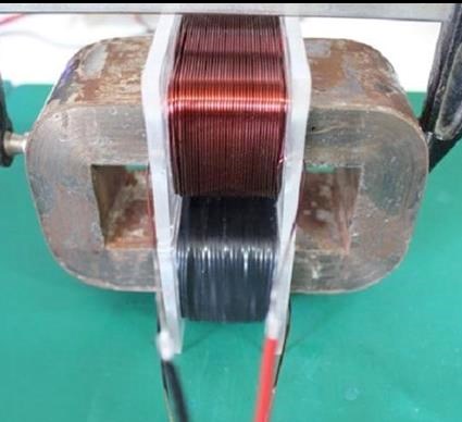
Transformer Test Rig# 1 with POC1 on other side of core from Primary.


Basically, just like Tinman but with a core.


Comments are welcome.

Thanks.

Adam.

Adam posted this 22 March 2024

Hello,

Just getting back to testing.

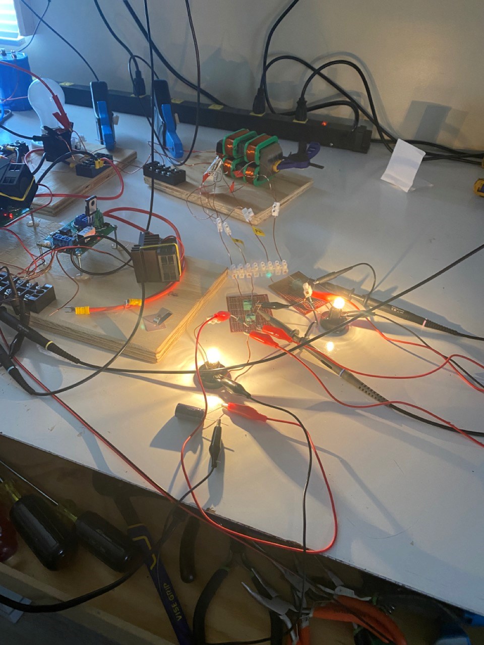
This is the setup.

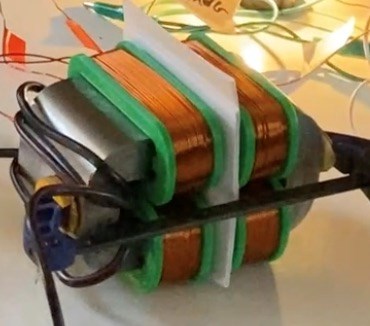
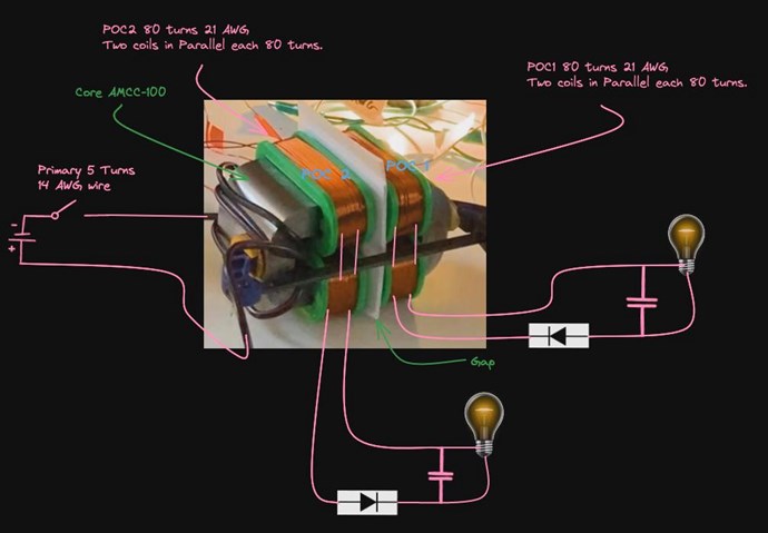
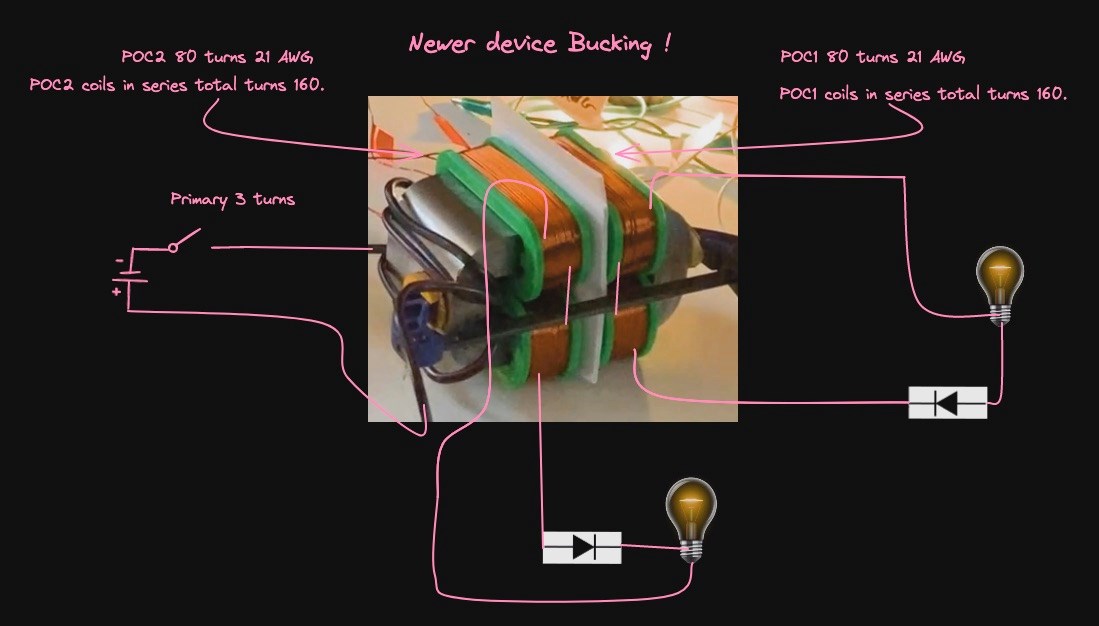
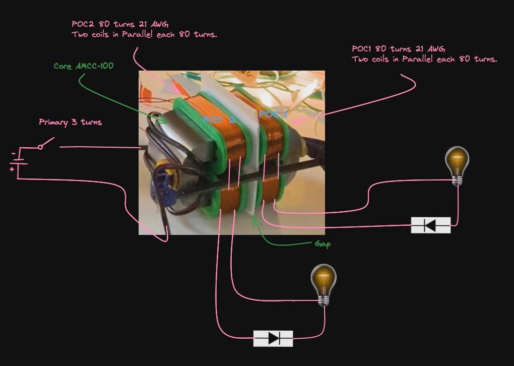
Two coils on left side of the gap are 80 turns each of 21AWG wire and wired in parallel through a diode and a Cap is in parallel to the bulb.

Two coils on Right side of the gap are 80 turns each of 21 AWG wire and wired in parallel through a diode and a Cap is in parallel to the bulb.

The coils on the right are POC1 coils or the coils that repulse the Primary Field.

I so far have had the best luck with having the bucking coils on each side of the gap rather than over the gap.

The Primary coil is on the left side between the POC2 coils with 5 turns of 14 AWG wire.

I have one bulb on each POC set of coils.

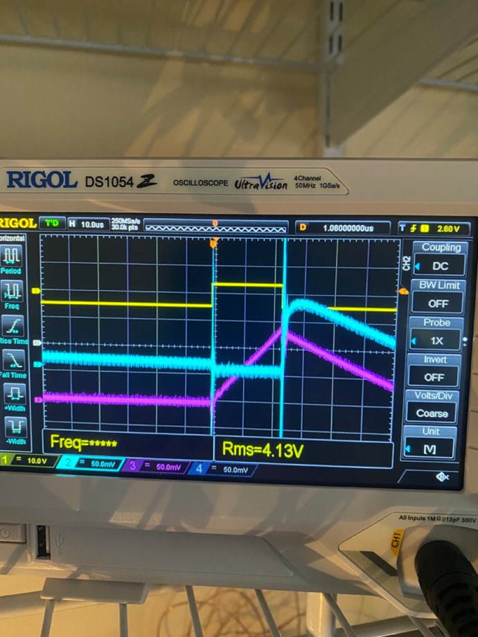
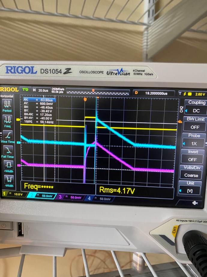
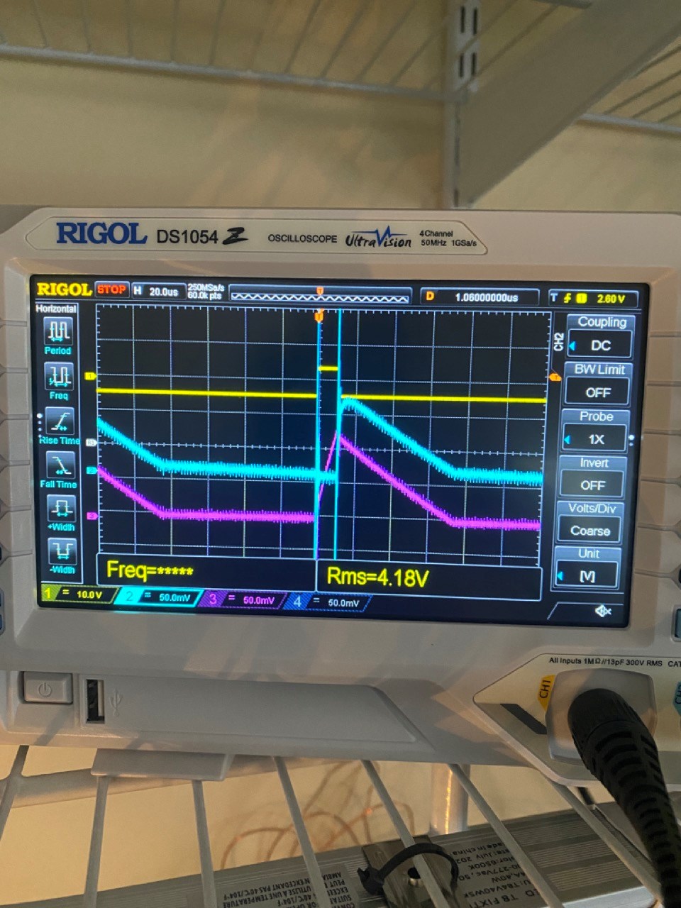
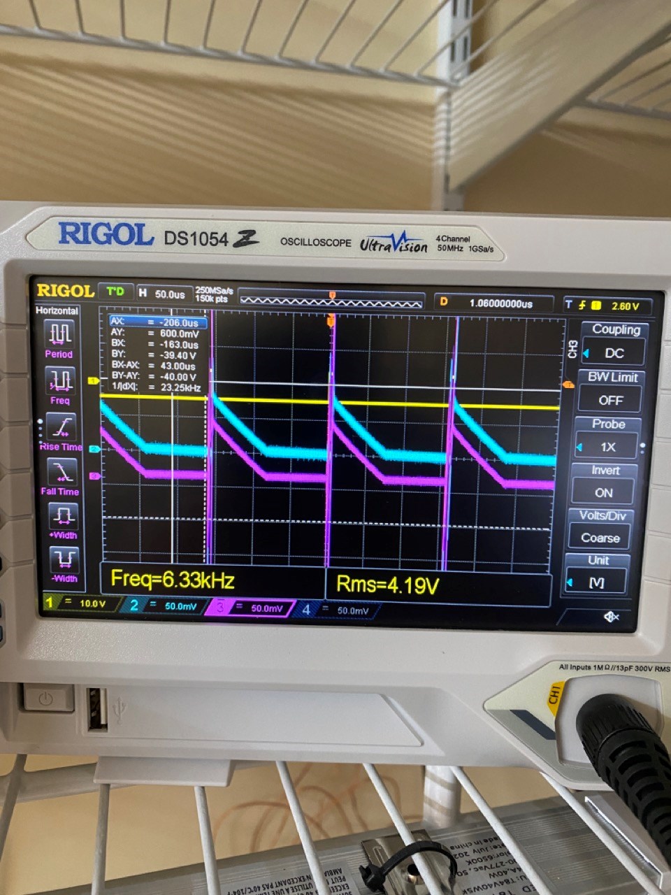
You can see that the pink trace is amps on the POC1 coils, and the blue trace is amps on POC2 coils. Yellow is the signal to the Primary switch.

This is the scope shots:

All in all I think the scope shots look good with this configuration.


I do not have good luck with having the primary wound over the top of POC1 (coil repulsing the primary) like Chris demonstrates. only when it’s over POC2 and POC1 is on the other side of the transformer do things work correctly for me. I do not understand why this is yet.

But I think I will go back to what Chris has shown with the Primary over POC1 and see whats going on.


Any Guidance or comments would be helpful.


Thanks.

Adam.

Adam posted this 4 weeks ago

Hello Chris,

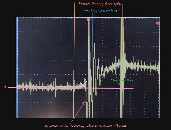
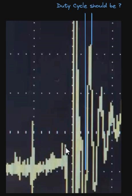
Something I have been thinking about after looking at the ringing of the POC coils during the on time primary pulse. The on time has a wave that goes below Zero meaning the coil is reversing several times in the time frame of the Primary being on.

This must be hurting all of us or making a very inefficient primary pulse.

So, I went back through some of your videos and noticed in video:   Non-Inductive Coil Experiment - Video Nine

You make a statement about frequency “The ringing can be used to find a frequency that could be more advantageous.”

Did you mean frequency or primary on time duty cycle?

Our current on time duty cycle is noted in Orange and the time I think it should be on is noted in Blue. I am using your scope shot for this investigation. As everyone has seen this shot and all our shots look almost the same if you zoom in.

My current setup I am using about 1% duty cycle, but this would need to probably be about 0.01% duty. Very Fast!

If I am correct, the problem is the amount of power to saturate the core going through the fet in that small time frame would blow the Fet! I am talking about higher power systems now not just lighting a few flashlight bulbs to understand the system.

So, to overcome this problem and to saturate the core it that time frame we would need to use a capacitive discharge either through a spark gap or an SCR?


Could you please comment on this thinking. If anyone else would like to comment on my thinking of this that would also be great.


Thanks.

Adam.

FringeIdeas posted this 4 weeks ago

Adam, I hope Chris has a few free minutes to dive into this question? Though I believe it goes beyond the scope of the original experiment (for other readers just starting out).

But a few days ago I went back through those videos and got to thinking about that, and was actually meaning to ask myself. I have some ideas, but I'll be honest I don't know.

WARNING: This is like 200% speculation coming up, and I'll keep it super short because I'm probably wrong. 😎

First idea is that if that is the frequency that the coils really like to talk to each other on, maybe that could be used for at least the rise time of the input, so for tuning.

Second idea gets into even more speculation. Last week I started watching the A Valon videos. Small thread here. A Valon's Ferro Resonance Circuits. It's about electron paramagnetic resonance(EPR) which from what I gather, has a few times been (erroneously) called ferro resonance, or ferromagnetic resonance. From what I can tell it's just a means to get the voltage up at a frequency, or a sub-harmonic, of where the electrons want to be excited.

And I'll leave it at that because, as I mentioned, I'm very possibly off track. I'm still messing with the some coils buck and some don't experiments. After that I plan to venture in to these other topics like EPR, etc.

Good questions, nice to see! Thanks!

Marcel

Adam posted this 4 weeks ago

Yes the first Idea is exactly what I'm stating too.

Thanks.

Adam

Chris posted this 4 weeks ago

Guys, 

Experiments are looking really good! Keep at it, learn as much as you can, an dyes, some of the theory/speculation here is on target!

Keep at it guys, I hope to have more time soon!

Best Wishes,

   Chris
We're Light Years Ahead!
Members Online:
What is a Scalar:

In physics, scalars are physical quantities that are unaffected by changes to a vector space basis. Scalars are often accompanied by units of measurement, as in "10 cm". Examples of scalar quantities are mass, distance, charge, volume, time, speed, and the magnitude of physical vectors in general.

You need to forget the Non-Sense that some spout with out knowing the actual Definition of the word Scalar! Some people talk absolute Bull Sh*t!

The pressure P in the formula P = pgh, pgh is a scalar that tells you the amount of this squashing force per unit area in a fluid.

A Scalar, having both direction and magnitude, can be anything! The Magnetic Field, a Charge moving, yet some Numb Nuts think it means Magic Science!

Message from God:

Hello my children. This is Yahweh, the one true Lord. You have found creation's secret. Now share it peacefully with the world.

Ref: Message from God written inside the Human Genome

God be in my head, and in my thinking.

God be in my eyes, and in my looking.

God be in my mouth, and in my speaking.

Oh, God be in my heart, and in my understanding.

Your Support:

More than anything else, your contributions to this forum are most important! We are trying to actively get all visitors involved, but we do only have a few main contributors, which are very much appreciated! If you would like to see more pages with more detailed experiments and answers, perhaps a contribution of another type maybe possible:

PayPal De-Platformed me!

They REFUSE to tell me why!

We now use Wise!

Donate
Use E-Mail: Chris at aboveunity.com
The content I am sharing is not only unique, but is changing the world as we know it! Please Support Us!
Thank You So Much!

Weeks High Earners:
The great Nikola Tesla:

Ere many generations pass, our machinery will be driven by a power obtainable at any point of the universe. This idea is not novel. Men have been led to it long ago by instinct or reason. It has been expressed in many ways, and in many places, in the history of old and new. We find it in the delightful myth of Antheus, who drives power from the earth; we find it among the subtle speculations of one of your splendid mathematicians, and in many hints and statements of thinkers of the present time. Throughout space there is energy. Is this energy static or kinetic? If static, our hopes are in vain; if kinetic - and this we know it is for certain - then it is a mere question of time when men will succeed in attaching their machinery to the very wheelwork of nature.

Experiments With Alternate Currents Of High Potential And High Frequency (February 1892).

Close