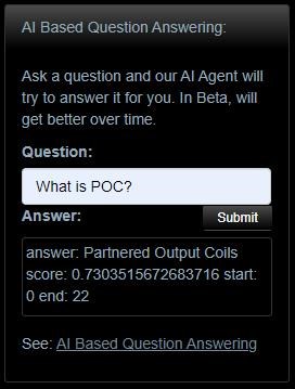
AI Based Question Answering for Members Only!

  • 471 Views
  • Last Post 5 weeks ago
Chris posted this 22 February 2024

My Friends,

As always, we lead the world in advanced Technologies and Cool Stuff!

Coming soon, an AI Based Question Answering System with all the data from this Forum, all questions answered instantly by an Artificial Intelligence, so smart and so accurate, that even I am impressed!

More coming soon, keep an eye on this thread!

Best Wishes,

   Chris

Order By: Standard | Newest | Votes
FringeIdeas posted this 28 February 2024

First query, I had to go with "Answer to the Ultimate Question of Life, the Universe, and Everything".

Hope I don't have to wait 7.5 million years 😃

But seriously, this is cool, I'll be messing around with this, thanks.

Marcel

AETHERIC_MIND posted this 28 February 2024


The Holy grail of idea. 

Nice to see this AI avenu coming soon.

Thx Chris and all

''Change is never easy but it's worth inertia''

Chris posted this 03 March 2024

My Friends,

Thank You for all of your Support!

The Question Answering System is working, its early stages and its a little on the slow side, but its working:


I have is working, but its slow and its intermittent at the moment.

Please be patient, its a work in progress, I am still working on, so please be patient with me.

Best Wishes,

   Chris

Chris posted this 09 March 2024

My Friends,

We have more working AI on our forum.

I am still working on this, but its working, its much faster, and its pretty damn cool!


Its pretty cool! If you have any issues, please let me know!

Best Wishes,

   Chris

thaelin posted this 09 March 2024

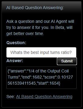
Had to ask the AI what would be the best Uf to Mh cap value for spike recovery would be. Got the answer of 2 to 3 hundred turns. Was worth the try anyhow. Still hunting the formula yet.

thay


Chris posted this 09 March 2024

Hi Thaelin,

The 'Context' is small, it has limits, and its entirely based on Partnered Output Coils, so asking questions based on the topic of this forum would give better results, with better scores, instead of a narrow guess, because the AI does not know, from the context, with a bad score.

It all makes sense, sensible questions within topic, and sensible answers should be achievable. Of course, we are not using Chat GPT here, its a closed source system, so we dont have access to this sort of AI yet! Even Chat GPT forgets your name after some 3K odd tokens! So I guess one has to have realistic expectations at the same time.

Best Wishes,

   Chris

thaelin posted this 10 March 2024

I have an old 10 card coin mining machine that I put chat gpt on just for fun. It could not answer either. Just got a long drawn out diatribe on things. Now that I see this AI is aimed for subjects of this site, I will Taylor my questions to things here. 

thay


JenkoRun posted this 10 March 2024

Evening all, I had to step away from the forums for a while. I tried asking the AI about this but it would not give an answer, can someone direct me to the sticky thread that specifically covers the principles and basics of the automatic impedance matching the POC shows please? At least I assume that's what it does.

I'm looking for information on how to prevent the load from detuning the system when attached or switching loads, is it something like this video or something else?

Chris posted this 10 March 2024

Hey Jenkorun,

Glad to hear you have given the AI QnA Bot a go, and yes, some questions, even if its along the lines of the Topic of this site, may sometimes be incoherent to some degree. AI is getting much better, but its still got a way to go.

In saying this, I am still working on this and am trying to make it more accurate and have better board spectrum context. In time, it will get better! For new comers, asking basic questions, that are not too advanced, and having a Context with the data in relation to the question, it generally is pretty accurate and does generally give very good answers. You could try asking questions a few different ways, this can give better answers, as key words will appear in different parts of the Context. Also, as time goes on, and the speed of the AI improves, I will broaden the Context to cover more topics. This will help immensely!

Regarding your Questions:


can someone direct me to the sticky thread that specifically covers the principles and basics of the automatic impedance matching the POC shows please? At least I assume that's what it does.


Both Questions are linked, so the answer to both will be provided below.

I'm looking for information on how to prevent the load from detuning the system when attached or switching loads, is it something like this video or something else?


This is another fantastic question!

Short Answer:

By stopping the change of Impedance under System Load.

Long Answer:

To answer this question, we need to first understand why Loading a System, changes the way a System behaves. Say we have a series of Ten Ohm Resistors, and each resistor is on a switch, a Transformer supplies 12 Volts to the Circuit and we have all of the Resistors in Parallel Switched Circuit, like so:
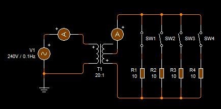
We know, from EE Class, that the equation for Resistors in Parallel, follows the following notation:
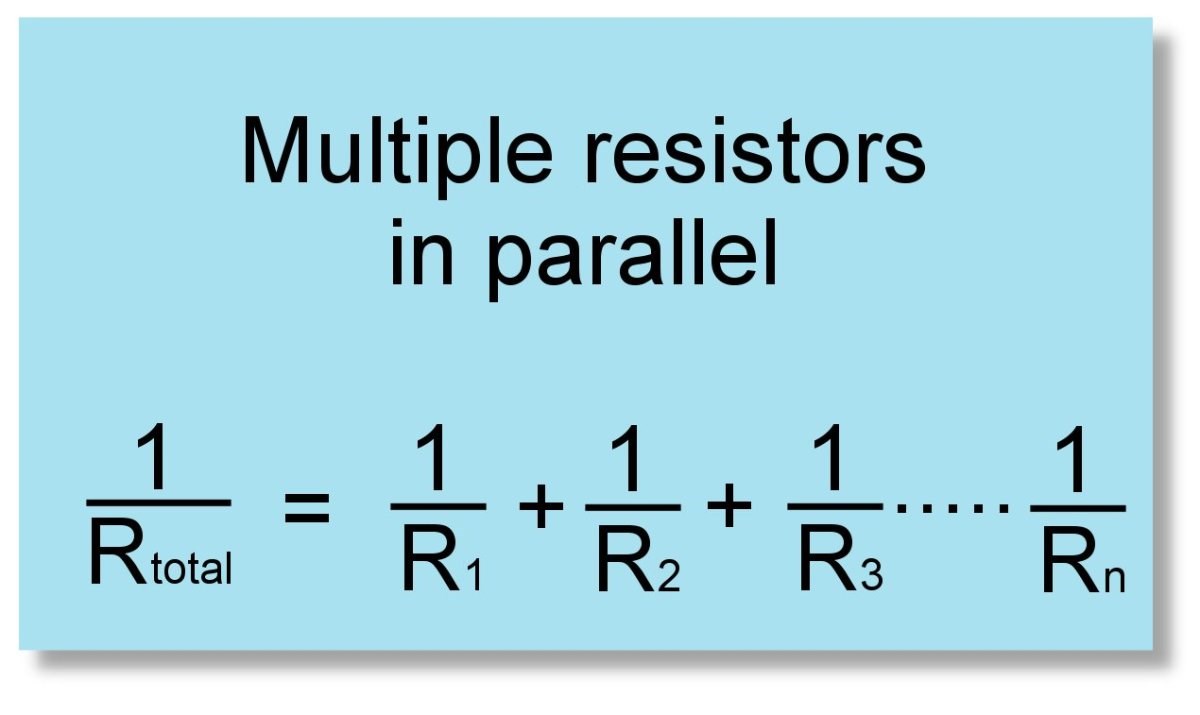


If we do some quick math:

  1. 1 / RTotal = 1/10 + 1/10 + 1/10 + 1/10 = 2.5 Ohms Total
  2. 1 / RTotal = 1/10 + 1/10 + 1/10 = 3.3 Ohms
  3. 1 / RTotal = 1/10 + 1/10 = 5 Ohms


So, in this situation, we get a lower Resistance than the single Resistor R, as the Load increases, the Current to the Load increases, because the Resistance of the load Decreases, but this is not the full story! There is more!

The Impedance of the Coils also decrease!

As the External Load increases, the Impedance of the Coils Decrease, making the Coils inside this Symmetrical, Conventional Transformer, capable of carrying more Current, thus, the Input of the Transformer will see the same, linear increase in Current, on the input, until we reach Saturation, and then the Input Current becomes Non-Linear. 

So, the Magnetic Field itself, changing, under load, changes the Impedance of the Coils, allowing change of Current inside the Coils on both the Input and Output, thus the Inductance of the Coils, because Inductance is the measure of Current Flow in the Coils, remember? also changes! A Conventional Transformer does have a Non-Linear Inductance change, this is seen when a Transformer Saturates, and sometimes can catch fire, because the Transformer has lost all of its Inductance:


So, how do we stop this occurring? How do we isolate the explained Changes? How do we use Coils to isolate the Input from the Output?

Superposition:

Superposition theorem states that in any linear, bilateral network where more than one source is present, the response across any element in the circuit is the sum of the responses obtained from each source considered separately. In contrast, all other sources are replaced by their internal resistance.

Ref: Superposition Theorem


If our Input Coil is exposed to an output Coil that is always opposed to the Change, Lenz's Law, then the Superposition Theorem says, we get a total MMF Vector Equation of: M.M.FPrimary + M.M.FSecondary = Zero!

And now, to answer your question: We need to change the way the Transformer works! We need to Introduce Asymmetry to a strictly Symmetrical discipline, and we need to use Superposition to change the equation seen above, from:

M.M.FPrimary + M.M.FSecondary = Zero

to:

M.M.FPrimary + M.M.FSecondary + M.M.FTertiary = M.M.FTertiary


I have shown everyone how to do this already, this is already fully explained technology, here on this forum!

 Start Here → Builders Guide to Aboveunity Machines


When you have M.M.FSecondary ≅ M.M.FTertiary, you have reached Magnetic Resonance! Thus, at Magnetic Resonance, your Input Coil is completely isolated from your Output Coils, because the Magnetic Field Vector, back on your Input Coil, cancel out, your Input Coil see's just as much Positive Force as it does Negative Force: 1 + -1 = 0 effect back on your Input! In real world application, this is not entirely accurate, your Input Coil can see Negative Power coming back, more than the Positive Power going in, so be aware of this.

In achieving this very easy task, you have the ability to have huge gains, because we have a fully open System, the system we have built, for a few dollars, now can extract as much Energy as one can from the specified Design and Geometry, as one wishes, with very little impact, negatively, on the Input!

If you read my pages, all of this is already fully explained!

Best Wishes,

   Chris

JenkoRun posted this 12 March 2024

Thanks for getting back to me Chris, I would like to bring up something though as this felt a bit convoluted, it took me a while to understand what you were saying, specifically these terms are being used in ways I, until now, had no association with (other than the parallel resistor calculations, though those should be in Parentheses according to my calculator)

I looked over the page on impedance matching and, if I understand correctly, the reverse direction of the windings causes the retarded fields to cancel out perfectly if built right which effectively neutralizes the impedance, and this is the method the POC uses to avoid Lenz resisting the input of the L1 exciter, leaving the L1 to freely excite the system regardless of what impedance changes occur due to the loads, is that correct?

If that is the case, how would one go about stopping the change of impedance between a load and a lone L2 output coil in a non-POC system? I'd like to get data on the principles that can be used for different kinds of machines if possible (even if the POC is superior).

Does the video I linked have any relevance to this effect? This is what the author spoke about it:

"Essentially this is a automatic impedance matching transformer. The single layer solenoid is in reality a half wave transmission line. The input travels down the transmission line to the pick up coil attached to the load. What is not absorbed by the nature of the load is then reflected back down the half wave resonator, the path to the load, then the reflection represents a full wave (180 degrees + 180 degrees = 360 or full wave).

Due to this when it returns to the primary, it is in phase with the next impulse from the signal generator and there is constructive interference. The next wave is then the original amplitude plus the reflection. This then travels back to the load where it is partially absorbed, and partially reflected. The next reflection repeats the aforementioned cycle to constructively add to the next pulse from the sig gen.

Within several cycles the impinging wave reaches an equilibrium with the load and an impedance match is had. What is not used is essentially saved for the next cycle in an electrically resonant "flywheel". The wave form of current and voltage are a perfect 90 degree phase differential.

I think this is very much the same as what you are accomplishing, however I did not use any iron within the resonant portion, so that I could accomplish the highest possible Q factor without core losses.

I dare say, you are simply reaching the "sweet spot" matching the impedance of the source to the load, hence the increase in efficiency and power transfer (maximum power transmission theorem). I could absolutely be incorrect on this as I did not read all posts and may have missed something, but thought I would comment none the less...or none the more? not sure which HA HA HA.

Andrew" -http://www.energeticforum.com/forum/energetic-forum-discussion/renewable-energy/12009-reactive-generator-research-for-everyone-to-share/page2#post345718


I'm sure you understand all that but I'm just going to write out a laymen's version of that for those who could benefit. In slightly more laymen's terms, the waveform comes along at 180 degrees due to the coil being a half wave resonator and is then reflected back at 360 degrees which makes it in-phase with the next pulse, building constructively instead of destructively until it balances itself out, nice and simple, easy to understand. This is the sort of understanding I was hoping to get from how the POC's impedance matching system works.


The issue presenting all this information without a primer is that is does not explain what is actually going on in the whole picture for people new to the concepts without deeper digging through a lot of information that, for people like me, is too much at once, especially when confronted with terms they're not familiar with

I was able to understand it this time but that became possible only recently with the exposure I've had from just general electric talk on the net over the last year, when I was around before I couldn't make heads or tales of anything. Or maybe that's just because I'm on the spectrum.

I think there would be great benefit in using more laymen language, or a primer, for these topics in the opening of each major topic thread before digging into the more extensive details, such as the example I used above. Covering every aspect of the complicated details is not necessary in the opening introduction, I've been able to make good progress in other areas of research by keeping it simple and using easily laymen language before tackling more the extensive details after, once I have a grasp on the basics then I'll be able to start touching on topics with terms I've never heard before.

Thanks for the info and directing me to the pages of relevance, side question: I asked before if LCR resonance was used in the device and you said it there wasn't, just magnetic resonance, since the POC has what is essentially an automatic lenz canceller effect does this mean the POC can be excited with 50/60Hz 3-phase input and the POC will remain useable?

Cheers.

Chris posted this 13 March 2024

Hey JenkoRun,

I have to say, to your questions:

I looked over the page on impedance matching and, if I understand correctly, the reverse direction of the windings causes the retarded fields to cancel out perfectly if built right which effectively neutralizes the impedance, and this is the method the POC uses to avoid Lenz resisting the input of the L1 exciter, leaving the L1 to freely excite the system regardless of what impedance changes occur due to the loads, is that correct?


I have to say, no, not really correct.

The Direction of the turns is important, but no, the direction of the turns, CW / CCW, has a no effect on the direction of the Magnetic Fields produced in the machine! There is an effect which is related to the CW / CCW direction of the turns, however, I believe is too early to go into further at this time, we can discuss this later on, when more people have more bench time experience.

The root cause of the Direction of the Magnetic Fields opposing each other, is 100% related to Faradays Law between POCOne and POCTwo.

Partnered Output Coils represent the Rotor and Stator Coils in an Electric Generator, each opposing each other, the Delta t, change in Time, is represented by the Input Coils frequency! The Input Coil is a regulator, it is an exciter, and that's all!

If the gurus out there, only just gave the Electric Generator a good study, and opened ones eyes to the limitation of this purely Symmetrical System, that Science has claimed completion of, the field of Electrodynamics, many decades ago, Sir Richard Feynmann claimed this way back in 65 or so. This is a misconception, a falsehood, and science should be ashamed of such arrogance at such an early stage of Humanities journey of scientific discovery!

Conventional Electrodynamics completely lacks 1/2 of a field that remains incomplete to this day! Symmetry is a small portion!

Asymmetry, as a whole, encapsulates Symmetry! Asymmetrical Systems are a part of Nature, so Science must incorporate Symmetry as a subset to Asymmetry and complete Science with the proper engineering of Asymmetrical Systems! Today, we have complete arrogance in the engineering of Asymmetrical Systems!

I have read your post twice now, and you are heading off in the wrong direction with this.

However, your questions all have answers here on this forum, and going through them again and again with different people is not what I want to spend my time on, I would rather help people with their experiments, as this really is the path to true discovery and knowledge! All you need do is follow what I have given you, and all answers will be right there as you progress through the replication information I have given!

Some things you talk about in your post are correct, some are a long ways wrong, but you will see all this as you read through and replicate the experiments I have already given!

If I may suggest, forget what you think you already know, and what you are actively trying to match or fit to existing science, because much of it is wrong, and start Replicating, this is where you can make progress! This is where you will gain an understanding that just cant be explained in pages and pages of naked text.

So rather than me going through and retyping information already given, in the next post, I hope to be able to help you with the replication you are working on.

Best Wishes,

   Chris

Chris posted this 5 weeks ago

My Friends,

I am still working on this topic! I see many very good questions coming through! So please keep them coming!

I am working on a bigger model, a much bigger Context, and more powerful answering of some of the tougher questions!

Thanks for your patience everyone, more very cool is coming! Work in progress here!

Best Wishes,

   Chris

We're Light Years Ahead!
Members Online:
What is a Scalar:

In physics, scalars are physical quantities that are unaffected by changes to a vector space basis. Scalars are often accompanied by units of measurement, as in "10 cm". Examples of scalar quantities are mass, distance, charge, volume, time, speed, and the magnitude of physical vectors in general.

You need to forget the Non-Sense that some spout with out knowing the actual Definition of the word Scalar! Some people talk absolute Bull Sh*t!

The pressure P in the formula P = pgh, pgh is a scalar that tells you the amount of this squashing force per unit area in a fluid.

A Scalar, having both direction and magnitude, can be anything! The Magnetic Field, a Charge moving, yet some Numb Nuts think it means Magic Science!

Message from God:

Hello my children. This is Yahweh, the one true Lord. You have found creation's secret. Now share it peacefully with the world.

Ref: Message from God written inside the Human Genome

God be in my head, and in my thinking.

God be in my eyes, and in my looking.

God be in my mouth, and in my speaking.

Oh, God be in my heart, and in my understanding.

Your Support:

More than anything else, your contributions to this forum are most important! We are trying to actively get all visitors involved, but we do only have a few main contributors, which are very much appreciated! If you would like to see more pages with more detailed experiments and answers, perhaps a contribution of another type maybe possible:

PayPal De-Platformed me!

They REFUSE to tell me why!

We now use Wise!

Donate
Use E-Mail: Chris at aboveunity.com

The content I am sharing is not only unique, but is changing the world as we know it! Please Support Us!

Thank You So Much!

Weeks High Earners:
The great Nikola Tesla:

Ere many generations pass, our machinery will be driven by a power obtainable at any point of the universe. This idea is not novel. Men have been led to it long ago by instinct or reason. It has been expressed in many ways, and in many places, in the history of old and new. We find it in the delightful myth of Antheus, who drives power from the earth; we find it among the subtle speculations of one of your splendid mathematicians, and in many hints and statements of thinkers of the present time. Throughout space there is energy. Is this energy static or kinetic? If static, our hopes are in vain; if kinetic - and this we know it is for certain - then it is a mere question of time when men will succeed in attaching their machinery to the very wheelwork of nature.

Experiments With Alternate Currents Of High Potential And High Frequency (February 1892).

Close