Ferrite at work

  • Topic Is Sticky
  • 12K Views
  • Last Post 13 December 2020
Jagau posted this 12 September 2020

An easy to assemble circuit that works, I have tried it myself and it is stable and functional.

This circuit is not from me it is from a Russian researcher who introduces himself under the nick name of "not a square" in russian  'Не квадрат'' 'on this website you can talk to him.
https://strannik-2.ru/index.php/forum/prakticheskaya-elektronika/220-u-menya-interesnaya-skhema?start=1485

The circuit has been working for 5 days now and the voltage is very stable. Here is the circuit:


I admit that I am happy with the result and that the ferrite fuel is doing its job. This circuit deserves to be studied and developed.

A view of the oscilloscope on the collector

I started at 2.3 volts and now after 5 days the circuit is stabilized at 2.457 volts


Jagau

Order By: Standard | Newest | Votes
Atti posted this 20 September 2020

 i plan to try also and will share my experience here.

We welcome you and excitedly.

Atti.

Jagau posted this 20 September 2020

Hello Atti
Are you using 1.2volt rechargeable batteries??


If this is the case with two batteries the full-charge voltage will be around what you mention 2.45 volts and it is normal that the max is reached, but if the voltage does not drop you have succeeded.

I have approximately the same result as you and voltage do not drop


Jagau

Jagau posted this 20 September 2020

Hi all

Another important detail:
Whether it is for this project or another, never let your DDM constantly connect to your circuit.
Why; the DDM has impedance and it eats the battery slowly, rather randomly taking time-to-time tests.

The input impedance of my DDM is 10 meghom, some lDDM have a lower impedance going up to 1 megohm, check this when you buy a DDM.

Here in this project we use low voltage.

P.S. On a microwave oven there is a parallel resistance of 10meg. on the capacitor,  it is used to discharge the capacitor when the microwave is stopped.

Jagau

Atti posted this 20 September 2020

Hi.

Jagau.
I used a non-self-oscillating oscillator to investigate why you can recharge the battery. Currently this is my opinion .You can also watch in the video.If my time allows, I will try another layout later.

Jagau posted this 20 September 2020

Hi Atti


You are correct, indeed experiment with various options that's how we move forward.
thank you for sharing your research.

@all
Do not try to recharge ordinary batteries, it will not work. Only rechargeable ones work and specifically NI-MH types

Jagau

Mimo posted this 20 September 2020

Hello team,
special thanks to Nekvadrat.

here is my setup (with the materials I had on hand):

- 2 ferrites dimensions: 36 X 22 X 15 mm (unknown material - old stock);
- 1 capacitor 2,2uF 250 V (C1) unpolarized, reference A50IT42202660K;
- 1 capacitor 0,66 uF (C2) unpolarized;
- 1 capacitor 3,2nF HT unpolarized (added in parallel with D2 for more luminosity on D1);
- 1 NPN 30 V transistor, 120 mHz, 2 A;

- L1, L2, L4, L5 and L6: Litz wire 0.1 mm X 180 strands;
- L3: 0.2mm x 19 strands tinned copper, stranded wire;
- R1 50 kΩ X 2 A (50 is sufficient, besides I did not have 100 k) ;

- V1: 2 AAA rechargeable batteries 1.2 V, 700mAh NiMH in series.

- I needed, as indicated above, to reverse the ends of L3.
- I secured the two loops of L6 with smalls nylon clamps.

I stopped adjusting R1 just as both leds stopped flashing.
D1 is very bright, D2 is much less.
V1 is currently stabilized at 2.280 V, after a gradual increase in voltage (starting at 2.150 V).
The circuit was powered up about 20 hours ago, so it will be necessary to monitor progress.

ferrite-at-work-Mimo

Greetings
Mimo

Jagau posted this 20 September 2020

Hi Mimo
Very interesting, and clean setup, I note that you use litz  wire
I can't wait to see the results with this type of wire.
thank you for sharing, we keep in touch.

P.S. I think we have a good team here,8 members have already tried and the results seem positive to most of you. it is certain that there will get positive results.


Jagau

YoElMiCrO posted this 20 September 2020

Hi all.

Today I replicate the circuit and submit it to analysis,
This week I tell you what I have found.
Also photos, of course!
Very interesting how it works, it's a bit complicated
to explain, in fact I still don't quite understand it.
But time to time, it's just that.

YoElMiCrO.

thaelin posted this 21 September 2020

   Up and going again. Had to resort to the  3055 as I blew the 2222 about 5 mins in. Showing 9.6 mhz and 9.6v on the collector. Battery is showing a rise at this time. Will be loging the voltage every .5 hr for a while tonite to see where it goes. Using a AAA NiMh to start with. Will try and find a set of bigger. Starting volts was 1.257

thay

Jagau posted this 21 September 2020

Welcome aboard Thaelin As you may have surely noticed, the adjustment of the 100K variable resistor is very important.

@mimo,  I am curious to know if Litz's cable is behaving well?

@YO, it looks like a very simple circuit but it has potential. One thing I noticed the 2 LEDs must be there.
If we remove one the circuit stops charging, as if the 2 leds act as a switch. The oscillator is easy to analyze but in the second rear BEMF of the second ferrite this is what I have not yet understood. It is as if two impulses crossed, this is what I see on the oscilloscope

Jagau

Nekvadrat posted this 21 September 2020

...репликации в большинстве случаев имеют положительный результат. Имеет смысл расположить тороиды определенным способом, к примеру друг над другом ...либо перпендикулярно. (могу и ошибиться, но ведь мы здесь для получения результата...)

Nekvadrat posted this 21 September 2020

....Jagau,...многие знают "переключатель Тесла". В данном варианте Вы можете попробовать свой переключатель, - заряженных АКБ, почему нет?

Jagau posted this 21 September 2020

Very judicious remark Nekvadrat,

I made different assemblies and in one of my set I noticed that the location of the 2 ferrites one in relation to the other seems important and even when they are very close to one of the otherwise it only worked if I removed L6 the coil in one turn, a curious phenomenon to study.
For the Tesla switch I did not experiment but will reread the details on Tesla.
Thank you for your help Nekvadrat
jagau

Mimo posted this 21 September 2020

@Jagau, and the team

yesterday I made a second identical device, except I did not use Litz wire, only 0.2mm x 19 strand tinned copper wire. The 50K potentiometer was not enough, I had to add a 40K resistor in series.

Led D1 is brighter with the Litz wire than on the other device.

I have just disconnected the small capacitor that I had placed in parallel with D2 and which made D1 much brighter. Immediately, the tension on V1 rises again.

On the second device, I had placed a small capacitor in parallel with D1 to get more brightness, but I just removed it. Here too, the tension on V1 rises again immediately.

I will observe until tomorrow the tension of V1 on both.
Perhaps it will be necessary to cut the power supply for a few minutes and measure the voltage of V1 at rest to have a better idea of ​​the real voltage. I will do it tomorrow.

Greetings
Mimo

Jagau posted this 21 September 2020

Hi Mimo,


We are in experimentation mode and that can help whatever brings us back.

I will also invite those who have succeeded, sometimes it is the small details and observations that you have made that help us all to move forward. Do not hesitate to tell us about your tests.


Jagau

thaelin posted this 22 September 2020

  Sadly the new one didn't charge. Ran down to .9 volts so called it off. Will have to rebuild and see how that goes.


Can someone post the ohms on the pot setting to see if mine was even close?


thay


Atti posted this 22 September 2020

Hey Jagau.

There may be other better solutions. Yes, this is an experimental mode right now. As you say.
At present, I continue to maintain my contention that this is in part desulfurizing.
Why do so many people run out of battery after a while?
I know a lot depends on the settings.
And that doesn’t mean there’s no option in this app.
If the process works, it should work not only with a small battery (1.2V) but also with a larger battery. For me, the question is, why does it work, how and for how long?

If you look at the oscilloscope diagram in the uploaded video, you can see that almost a quarter of the current returns to the battery. Why?
I think this is a forward switching in asymmetric mode.
The circle is not self-vibrating here. So the control.
The diode is replaced by an LED connected in series with another transformer.
When this other transformer is loaded with the correct polarity, it works similarly to this arrangement.
This is Chris' layout.  

One has loosely coupled coils. In the other, the coils are on two transformers.
Thus, if one of the columns is loaded with the correct polarity, the self-induction voltage on the load on the control column and on the control coil will increase.
This is returned to the battery. The only question is how much we will use and how much we can miss.

Jagau and everyone.
If not, could you show an oscilloscope image of the recorded image? Thus, it would turn out that the phenomenon is similar in others.

(i hope the google translation is understandable, but if anyone bothers you let me know)

Atti.

Mimo posted this 22 September 2020

@thaelin,
here is the value of the potentiometer of my 2 devices:
44.2K for the one with the Litz wire and 40.4K for the one with the tinned copper wire. With this setting, the LEDs are very bright and do not flash.
Check the correct order of your connections, because this assembly does not present any difficulty, it must light up as soon as the power is turned on, either in flashing or fixed mode. The potentiometer must be adjusted at the limit of the flashing / fixed LEDs. Remember to reverse the two ends of L3 from the diagram in the first post above. Check the data sheet of your transistor, its base is not always the middle leg. Obviously, scrupulously respect the winding directions of the coils, including L6 placed in 8.

For all, according to my findings:

1 / By adjusting the potentiometer so that the 2 LEDs flash quickly, you obtain a complete self-charge of the batteries, within a time which depends on the initial voltage, but at most in a few hours. The voltage then slightly exceeds 2.4 volts. When the LEDs are on steadily, the complete self-charging of the batteries also operates, within a slightly longer time and the maximum voltage is slightly lower, but still higher than 2.3 Volts.

2 / I brought the two tori together and positioned them in all possible arrangements. I did not see any improvement in the brightness of the LEDs or in the evolution of the voltage.

3 / On my device with the Litz wire, the D1 led is slightly brighter on D2. On the other device, D1 and D2 have approximately the same brightness. The advantage with Litz's thread is very moderate: D1 a little brighter, but D2 a little less than on the other device.

4 / By placing a capacitor of very small value in parallel with D1 or D2 (test with a panel of capacitors to find the right value), we obtain a very significant increase in the brightness of D1, but the voltage of the battery drops .

5 / By placing a neodymium magnet between L4 and l5, North against the outer edge of the torus, and with an adjustment of the potentiometer, I succeeded in lighting 4 leds connected in parallel, very bright. The voltage has dropped to around 1.6V. I did not continue the experiment beyond a few minutes. I removed the magnet and set to classic mode. This morning, the battery had fully recovered and was around 2.4 Volts.

Greetings
Mimo

Jagau posted this 22 September 2020

Hi Mimo


You shared valuable information. After having made various tests that you have realized the tension to drop a few times but as you said at the end;


This morning, the battery had fully recovered and was around 2.4 Volts.


You are proof that it works. And several others have also succeeded, just follow the plan as indicated by Nekvadrta.

My potentiometer is very close to your 49K value, it looks the same.
Your advice is very relevant and I believe that several will benefit from it, thank you Mimo.

I will post more photos that can help others succeed.

Jagau

Jagau posted this 22 September 2020

Hi Atti


I use NIMH rechargeable batteries, not regular batteries. The batteries did not have time to sulphate a NI-MH battery does not contain any sulfite, it is composed of nickel hydroxide for the positive electrode and for the negative electrode use an alloy that absorbs hydrogen. They lose their efficiency by degradation of materials they are not recoverable.

When you run a project in selfrunner mode like this, the batteries must constantly power the circuit and recharge at the same time.
The beauty of this project is that it works, we have several that have been successful and it's up to us to try to find out how.
This is what we are all doing together.


@ all

On another Russian forum I found this pdf which can be helpful, it is in Russian but you can translate it easily with google translate. See attach pdf

 Jagau

Attached Files

Wistiti posted this 22 September 2020

Hey Jagau.

It's me or in the .pdf you shared L4 and L5 are also bifilar?

Thank you!


ps: witch free translator do you suggest?

Jagau posted this 22 September 2020

Hi wistiti
The pdf provided is not from Nekvadrat, it is that another one who made it is a kind of summary that he took everywhere on different sites.
If you reread carefully he says it clearly and I quote him:


To facilitate the perception, I drew transformers on the cores.

This is to facilitate understanding it is not as the author did.


I use a BD139 transistor


Jagau

Wistiti posted this 22 September 2020

Ok thanks for your reply.

Im not looking for a transistor suggestion but a translator.

Jagau posted this 22 September 2020

On another Russian forum I found this pdf which can be helpful, it is in Russian but you can translate

it easily with google translate

Jagau

thaelin posted this 22 September 2020

Google failed. I used Bing and had to translate page then copy to text file. Was going to just add the text file but see no link to add file. So will just insert it here.


Good time readers, subscribers, and all those who just wandered into this page! Today we will talk about an interesting scheme,
repetition, which for a few days was just a record! And even in the open mode, which in itself is an event in the world of Free
Energy Seekers. The author of the scheme is a free energy seeker from Ukraine, known in many forums under the nickname"Not a square".
It's actually a diagram.

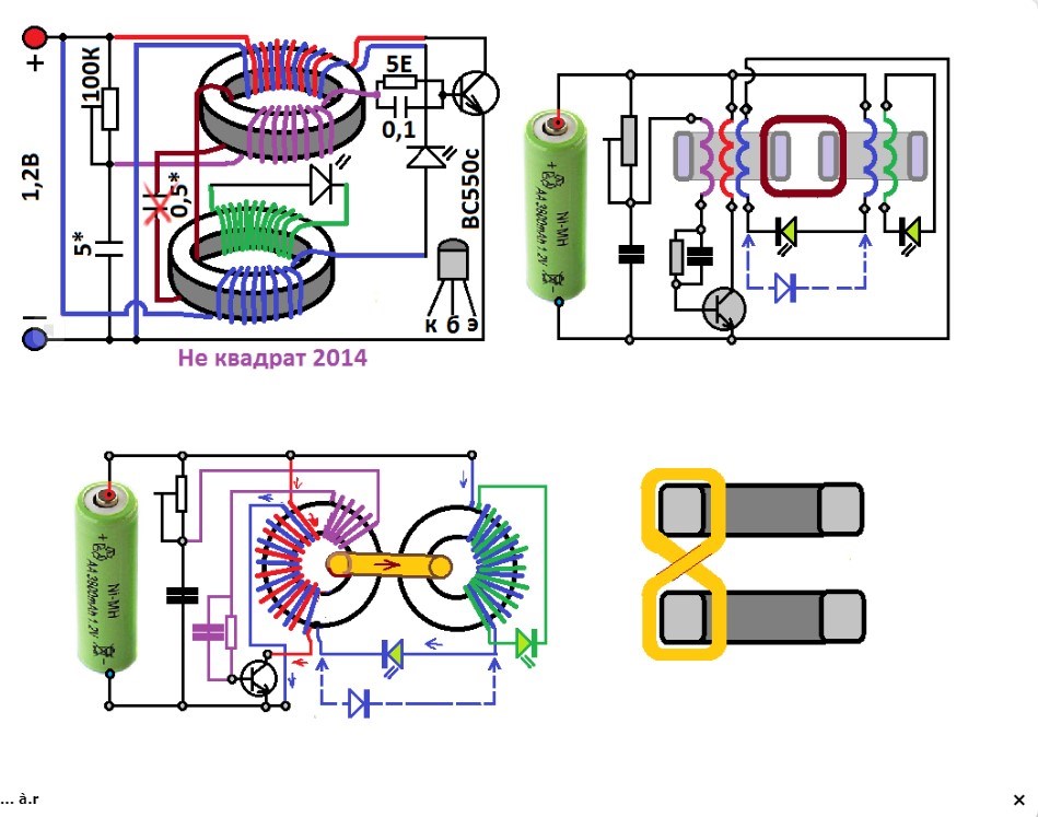
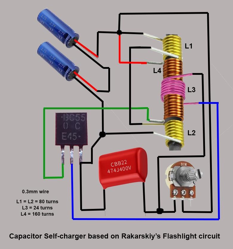
Схема рекуперационного фонарика Автор "Не квадрат", Украина
Scheme of Recovery Lantern Author "Not Square", Ukraine

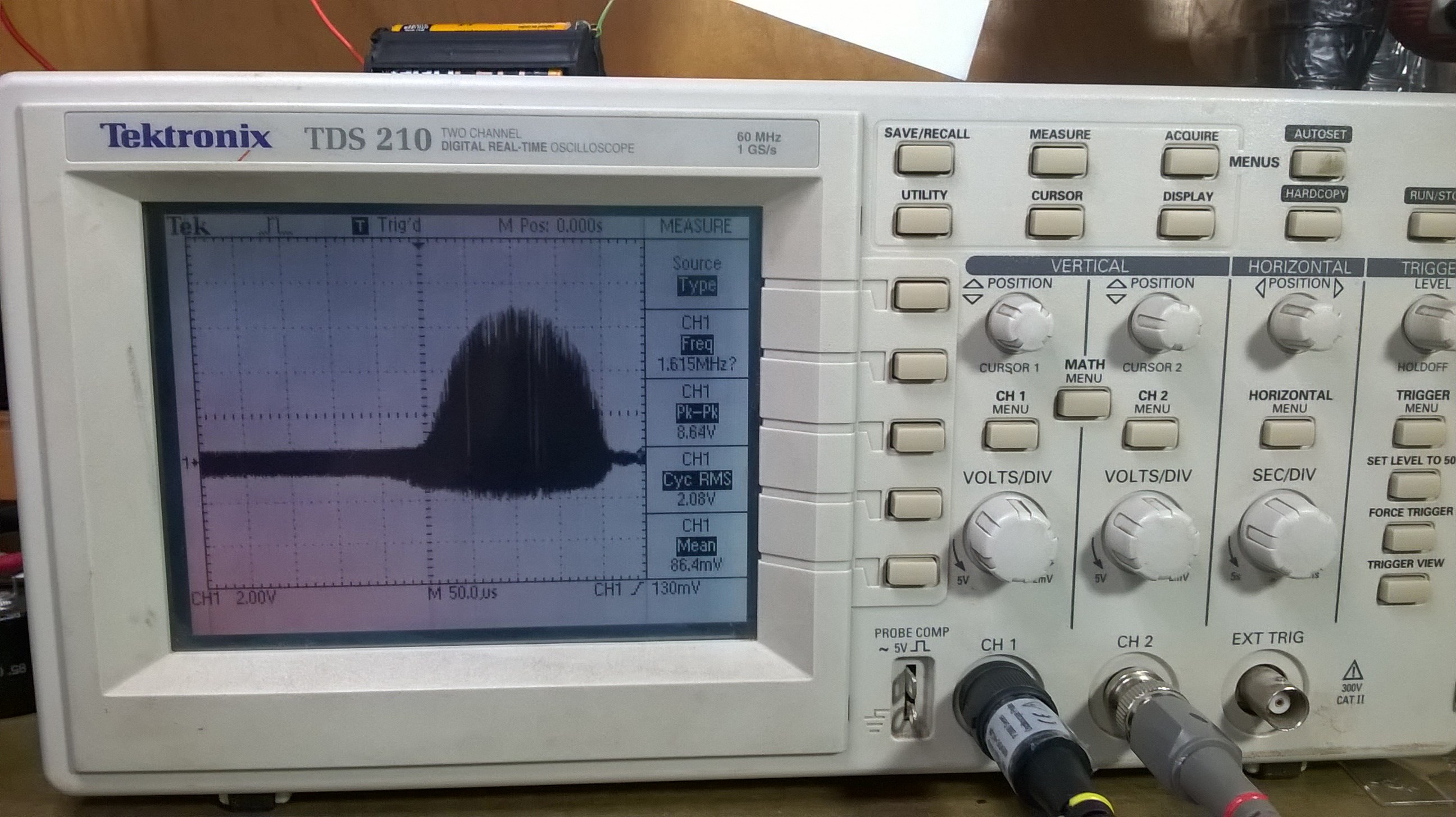
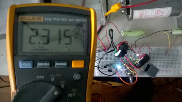
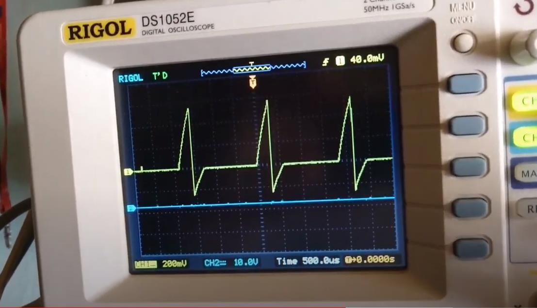
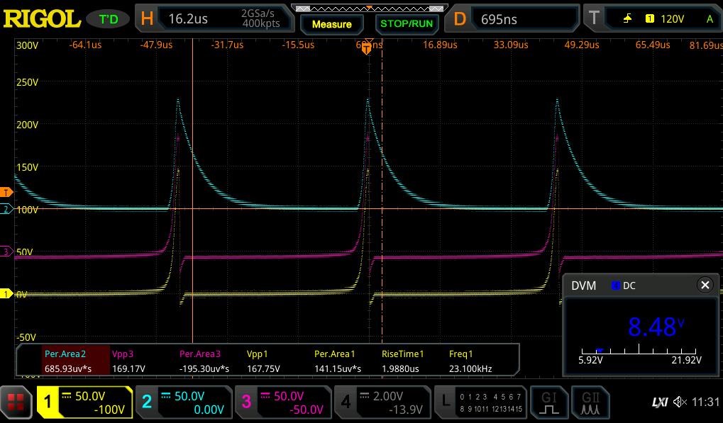
... don't get me wrong, I've been looking for a long, long time. Today, of course, the experience of 2014, it is difficult to
remember, but the scheme is even a working layout, photos and oscillograms ...

This finder went further and increased the size and tension of the source. This replicator has two stable devices, with different
parameters of components. This means only one thing - the working principle of the scheme is already repeated.

A few more searcher posts under the name "Transistor"

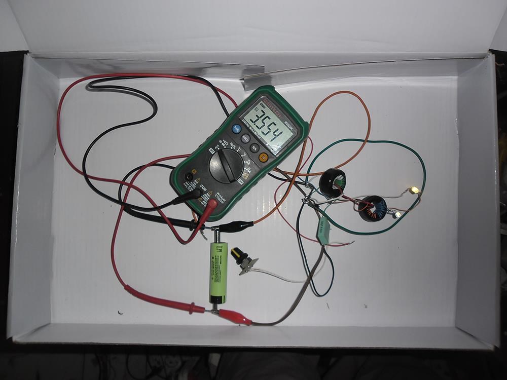
For the fifth day the generator assembled as a night light is not squared. During the day the battery rose to 3.8 volts, and then
the controller akb centalized the charge by 3.8 volts, along with the load - 3 LEDs. It's a joy. The forums are full of stagnation
and no progress. You have to start somewhere. If you have something interesting, share it. Criticism to do it is more easy than to
take soldering iron in hand.
What did you say, "transistor"? I transfer in one day the recovery system (reverse impulse), charged the powering AKB from the mobile
phone, which is constructively built into the mini-controller level of charge. This node does not allow the voltage on the battery to
rise in the six 3.8 volts. For dummies and investigators I will explain: the voltage of the pulse of the charge is above the level
of 3.8B with a current component sufficient to charge the battery.

Another post given by the seeker

... Without it, the brightness of the glow depends on it. Guys how can you talk about the work of the scheme without collecting it
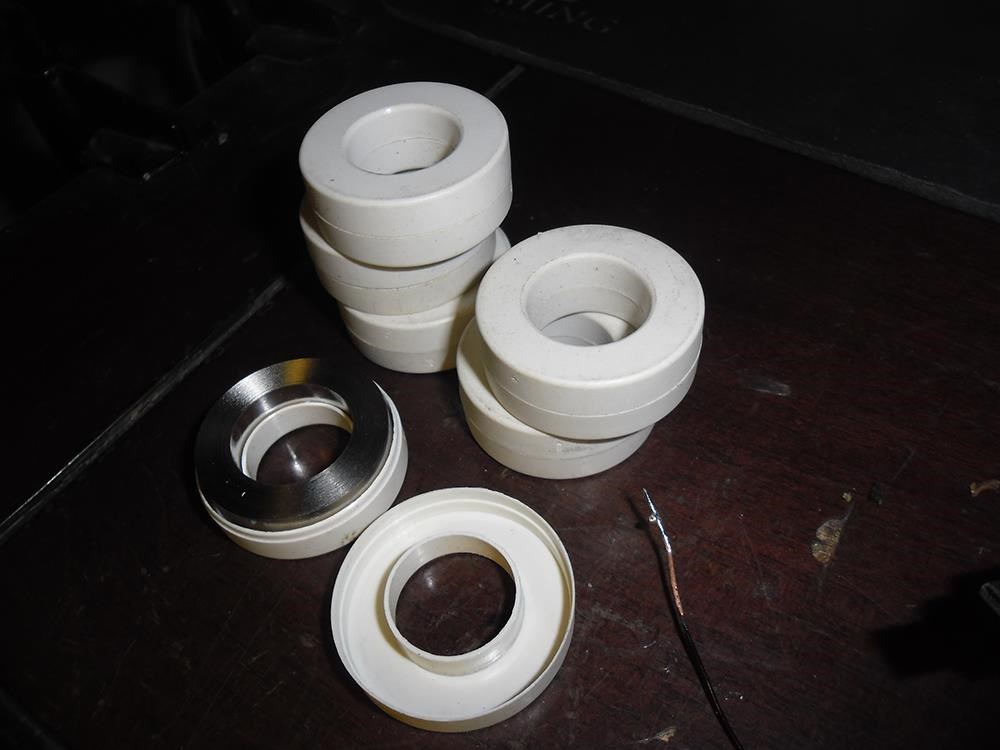
and not experiencing it? That would collect it and fix a couple of hours. The layout on armored cores works worse. The diode stands
according to the author's scheme ...
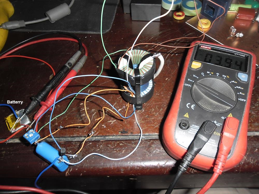
... Well, about the layouts, I do not have cool devices except the arrow and electronic tester can do it well. As a result, 10 days
I even got used to and relatives too that in the hall in the corridor and in the basement around the clock there is a light. And when
I ran them there and there were no three volts. What is interesting when adjusting the shift in the direction of the increase in
current increases the current of the transistor and the frequency of the generator as well as the charging current. I'm already
working on a new generator in the case of the factory lantern 5 LED as I finish. If all goes well in the future car akb with a
powerful generator of this type and already with powerful ladder lamps for lighting ...

... Basic and collector windings are not included as blocking.
It follows that without led Led1 the circuit will not start.
Moreover, the beginning of the transistor's opening with a base voltage instantly results in the triggering of the Led1 diode due
to two windings, which are additional supports for it. One of these windings has a constant time, given by the capacitor 0.5. So
the burning time of this LED is determined by this capacitor (in the first approximation). Without it , time is determined by the
fading of current in the turn of communication.
Once Led1 is extinguished, the transistor is shut down by the result of a locking voltage on the base winding of the transistor.
At this point, Led2 takes over the self-induction of the second ring, developed through the bond revolution and the capacitor 0.5.
The charge, which"settlement" at the transition of the collector-emitter at the expense of the OEDS of the first tr-ra, then goes
back to the source through the same collector winding.
The scheme differs from the usual blocking in that the closure of the transistor is not associated with saturation - neither the
transformer (it is saturated), nor the transistor. The closing process is managed by Led1 in the diagram described above.
Also, the current consumption from the source in the opening phase of the transistor here is much more than the usual blocking -
at the expense of Led1. ...
This is the opinion I have cited for the fact that the analysis of the scheme is different for everyone.

There are still repetitions of this scheme of Not Square.


The quote: "He is also very capricious to the choice of details. After all, 12 to 17 MHz is not a hoarse. By giving away the second
ICE you can raise the amplitude with your hand, and even more than with LED. It is better to put a high-frequency transistor. For
example, the same CT3102, but better higher power. I think it's fashionable to make a composite emitter repeater. In general, gene
class, seven feet under the keel! If two people already write that the accu is charging, then probably it is."


Цитата: "Он также очень капризен к выбору деталей. Все таки от 12 до 17 МГц это не хухры мухры. Отпаяв второй ЛЕД можно рукой
амплитуду повышать , да еще и больше, чем со светодиодом. Транзистор лучше поставить высокочастотный. Например тот же КТ3102,
но лучше повыше мощностью. Думаю модно делать составной по типу эмиттерный повторитель. В общем ген класс, семь футов под килем!
Если уже двое пишут, что акку заряжается, то наверное это так."
The quote: "He is also very capricious to the choice of details. After all, 12 to 17 MHz is not a hoarse. By giving away the second
ICE you can raise the amplitude with your hand, and even more than with LED. It is better to put a high-frequency transistor. For
example, the same CT3102, but better higher power. I think it's fashionable to make a composite emitter repeater. In general, gene
class, seven feet under the keel! If two people already write that the accu is charging, then probably it is."


Repetition of the third (nickname "AND")

Цитата: "На общей волне энтузиазма, тоже собрал схему Не квадрата. Действительно хватило 30 минут. Заработала с первого раза.
Транзистор кт3102АМ. Сколько будет работать, посмотрим. Не квадрат, спасибо!"
The quote: "On the general wave of enthusiasm, too, assembled a scheme not square. It really took 30 minutes. Earned the first time.
Transistor ct3102AM. How much will work, we'll see. Don't square, thank you!"

These materials from the website "STRANNIK-2"


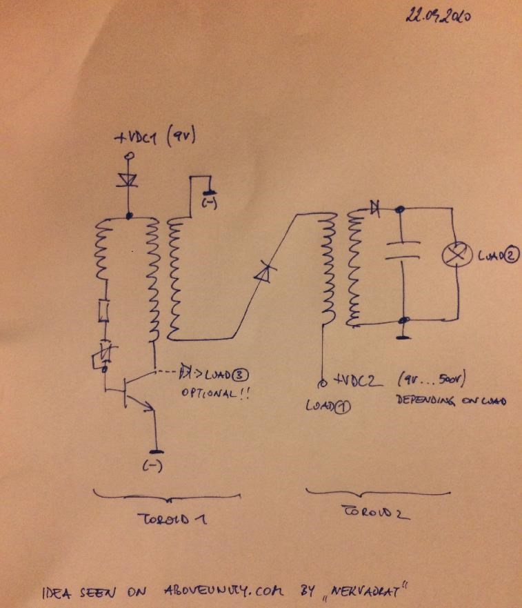
My "vision" of the work scheme:


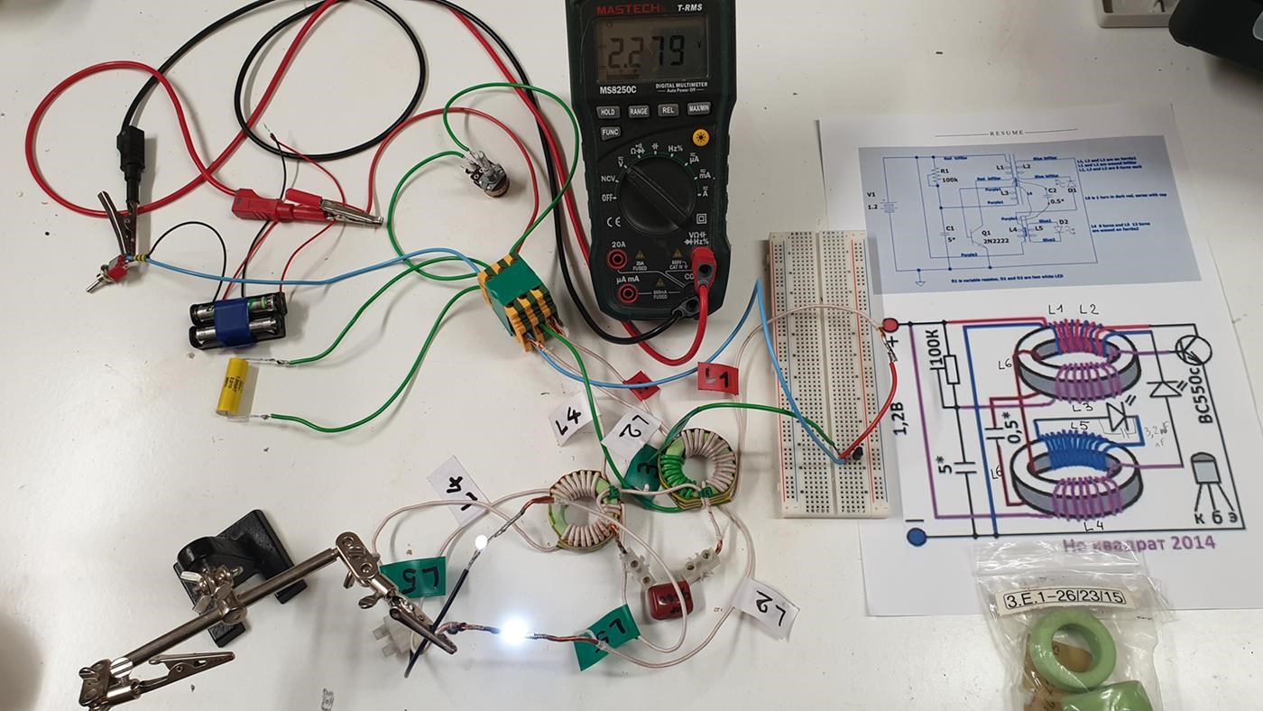
I have drawn "transformers" on the cores (cores) for ease of perception. In design we have: Block generator system (R1-C1-L4-VT1)
which is constructively placed at the core of the T1 transformer, together with windings: Bifilara (L1-L2/1) and 0.5 revolution (L5/1).
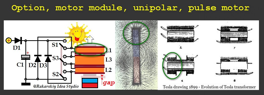
In fact, the work of a transistor is set on this core. The second core forms the Transformer Tr2 with windings of the second bifilar
(L3-L2/2) and 0.5 revolutions (L5/2). We have the connection of both cores through the L2 and L5 sections of which form a common
"inductive" connection. How can the scheme work.

When the battery is connected to the circuit, the elements of the circuit have current. The current flows in the L2 winding, through
both sections and led Led 1. If the voltage of the source is sufficient, it will light up if not enough, accordingly will not light up.
To the base of the transistor, through the winding L4, the same comes current. In the L5 winding, the current will only result from the
oncoming currents of L2 and L4 windings. there are still many nuances, perhaps, but for the first understanding is enough. The incoming
current to the base of the transistor opens it. And the current begins to flow through the L1 winding. since this winding has half as
much resistance as the two L2 windings consistently, the current will be larger in it, respectively the core will be remagnetized, and
through the winding L5, will give the impulse to magnetize to the second core. At the same time, the current in the L2 winding will not
change its direction, and the voltage in this thread will increase, which will cause the glow of the LED Led 1. At the same time, the
current in the L3 winding for its glow has the opposite direction (yes I'm not mistaken. And the main current in the L1 winding locks
the current in the control winding L4, which causes the transistor to shut down. (this is an element of the block generator work). At
the moment of switching off, we have a "bloated" magnetic field in both cores, and a promise to self-induction in the system.
Self-induction is if just the occurrence of EDS induction, with the"absorption of your own magnetic field coil"

Due to the phenomenon of self-induction in the electrical circuit with the source of EDS at the circuit is installed not instantly,
but after a while. Similar processes occur in the case of a chain-breaking,and(with a sharp blur) the magnitude of EDS self-induction
can at this point significantly exceed the EDS of the source.
We are interested in the processes precisely when the chain is blurred. But we should not forget that the current in the chain will
flow according to the rule of the Right Hand (in our case " for thesolenoid"). It should also be taken into account that the current
caused by the magnetic field will form in the thread in which conditions for it will be more favorable. This is a closed circuit and
resistance to the general circuit. There are a lot of controversial moments at first glance, but first we will try to understand. We
will deal with the rule of charge of the AKB.

The main charge is current and voltage. In order for the current to start moving towards the battery, the voltage of the "external
source" must exceed the battery voltage by N times. Also resistance elements should also be appropriate, naturally and the potential
of the field. If the voltage of EDS self-induction depends on the frequency, magnitude of magnetic induction and the length of the
conductor affected by this magnetic induction (and in our country it has a waning character), which we can roughly calculate according
to the formula:


EDS(Volts) )


As we see the power of current in our formula of definition of EDS is not! The current measure should be considered, according to
another formula - according to the law of Om for the full chain, with a little clarification.


I (A) - EDS - U bat. / R + Rn +r0

The current measure will depend on the difference in voltages between EDS self-induction and battery voltage, divided by the amount
of resistance to the recycling circuit. So, our charging current, this measure of EDS is not up to zero, but before the battery voltage.


To meet the sufficient condition, the guaranteed battery charge is suitable for us only a thread with the windings of L2 (L2/1 q L2/2).
It remains only to clarify whether the current flows through the LED, in the opposite direction? Let's turn to the omniscient network
with a request and find such material.

*The voltage of the LEDs is applied in the opposite direction.

The 25 volt voltage applied in reverse voltage will disable the crystal, with a voltage of 12 to 15 volts in the opposite direction
completely safe for the LED. The working voltage of the LEDs app in the opposite direction does not ignite and does not disable the
crystal.

As we can see, this is also not classified data. The current of self-induction into the battery in the non-square scheme comes exactly
by this way, and the LED in this switch register does not burn. At the same time, L2 windings, connected consistently, act as if
separate components absorbing each of its core field by increasing tension. In this switch register

It turns out that the work, short closed winding L5 through both cores remains unclear. At the moment of inclusion of the L1 winding
with the appropriate direction of the current, in the winding L5 there is a current of the opposite direction, which excites the
magnetic field of the second core. Probably this combination does not give the cores, do not achieve full saturation. During the
register of induction pulse induction, the direction of the current in the L5 winding will be the opposite direction of the current
of the L2 thread self-induction, which will have a beneficial effect on the process of utilization of the stored magnetic field energy
in both cores. For each battery voltage, you need to calculate the parameters of the device personally, but these are the details of the
design.

In my opinion. it is appropriate to supplement this scheme with two elements: VD1 Diode and Stabilizentron VD2. This is if the scheme
is done at great strain. Well and the led chain Led1 add a matching resistor, so that the reverse diode has dimed the LED with a
resistor.

Not a square smart, that's why he passed by and did not develop further do not know. The only thing left is a power option, which I
will consider with the participants of the "Source" project. This scheme can be assembled by anyone. who little-meaning with circuitry.
Soldering is not enough to hold, you also need to think.

Wistiti posted this 22 September 2020

Hi team! Just let you know I have build the variant with bifilar on both toroid (like my question to Jagau above) and it's also work. I use 2 x aa nimh battery's for the source. Start 1 hour ago at 2,136v and I'm now at 2,156v.

Really interesting circuit.

Jagau posted this 22 September 2020

Hi wistiti
A second try and it works for you, perseverance always pays wistiti and let's go.

As several seemed to have problems for the last document submitted, I translated it to you in English with google translate

in pdf format

Et en francais pour toi Wistiti


Jagau

Attached Files

Wistiti posted this 23 September 2020

Hahaha! Merci Jagau, c'est bien aimable.

Project still climbing. 2,159v it is slow but it goes!

thaelin posted this 23 September 2020

Is anyone having troubles burning out the D1? I have now taken out 3. Installed a standard diode and now system seems to be charging as it should. Started a log just now to see where it goes. Will leave it on all night and check again.

@jagau

   I am now seeing the same hump wave form you posted about the 17th with the internal form the same too. I sure hope this is finally a working unit. Have made 6 now and was really getting frustrated with it. Time will tell.

thay

L0stf0x posted this 23 September 2020

Wistiti my friend good to hear its working for you too!

I also run it for several days I use a Li-ion Battery started at 2.651V and slowly went to 3.554V and stayed there for almost 1 day. I will let it run..

Now its time to try different things that will make it more efficient. to try bifilar on both coils like Wistiti did successfully,

or double turns at coils ., also to build a 12v version with more LEDs, etc

Today if I have time I will build one using my best nano-perm cores with extreme permeability to see the differences. 

Jagau posted this 23 September 2020


Good morning all


Yes you're right Thaelin, it seems easy to build but it requires attention during assembly. If you have the same waveform as me, the ferrites are at work, well done you did.

@Lostfox, I see you are a real experimenter, you have several ideas for the design and different ways to test it, I will follow with interest and thank you for sharing your knowledge with all.


I invite those who have succeeded and who follow from outside the forum to join Aboveunity.com and thus be able to share your knowledge with us. It's free and as you've probably noticed, there is mutual respect among the members and a lot of mutual support.

Jagau

L0stf0x posted this 23 September 2020

Jagau first of all thank you for the circuit, it is really interesting! Secondly I am just a simple experimenter, at the lowest level than the other guys in here,  but thanks for your encouraging words wink

Indeed as I see it Nanoperm cores gives faster charging!! I got this little Li-po battery from 3.40v to 3.94v in few minutes and raising as we speak!! I know the battery has low capacity so faster charging is normal, but I will check Li-ion as well to be sure.

I ll try some more variations I have in my mind .. I will keep you updated guys.


Jagau posted this 23 September 2020

I think we use the same ferrite Lostfox.
The one I have is the Ferroxicube 3E27 epoxy coated
Magnetic permeability of 6000 and with that everything has been working wonderfully for 14 days and yes 2 weeks now. The tension does not drop and I am as you say fascinated by this circuit which requires that to be studied. I have several theories now and plan to talk to you soon.

After 14 days Losfox I think we have a real selfrunner in our labs, what do you think?
Jagau

Jagau posted this 23 September 2020

Another drawing made by Rakarskiy all in colors which could help to make the circuit of Nekvadrat.


To note on the base of the transistor the capacitor 0.1uf in parallel with the resistance of 5 ohms, probably to give more stability to the circuit, therefore to try.
jagau

L0stf0x posted this 23 September 2020

Nice drawings Jagau ! 

I don't remember their type but they are not ceramic type, they have plastic cup on outside and nanocrystal tape inside. Their permeability as far as I remember was from 40.000 to 70.000. But yes the best core material will be more productive here.

It indeed looks to be a self runner! I will try to run it with 12v using 3 li-ion batteries 18650 - 3400mAh each. So the changes should be the transistor to be high power one and maybe a resistor 100 ohm 1-2w resistor in series with the potentiometer may also required. Also 3-4 Leds in series will substitute the single ones. Mosfets and IGBTs also need to be tested.

Rakarskiy posted this 23 September 2020

Доброго здоровья всем! Я добавлю немного материала по схеме "не квадрат"! У меня есть собственное видение того, как работает эта схема. В любой энергетической отрасли важным моментом является индукция. Феррит не имеет хороших показателей. Сердечник должен быть выполнен с хорошими показателями инерции и индукции поля. В этом случае добавьте диод в противоположном направлении к светодиоду. Но самое лучшее решение-рассчитать схему по параметрам.

https://translate.google.com.ua/translate?hl=ru&sl=ru&tl=en&u=https%3A%2F%2Fzen.yandex.ru%2Fmedia%2Fid%2F5c01a2bcbf4b0f04178227d6%2Fvechnyi-fonarik-ili-mini-btg-5d1c397ecc20a700ae50f17c

Исходя из логики, я упростил схему, но в этом варианте нужно более корректно подходить к расчету схем, лучше делать это на железном сердечнике.

https://translate.google.com.ua/translate?hl=ru&sl=ru&tl=en&u=https%3A%2F%2Fzen.yandex.ru%2Fmedia%2Fid%2F5c01a2bcbf4b0f04178227d6%2Fpolojitelnoe-i-otricatelnoe-elektrichestvo-svobodnoi-energii-5d6e9f4efebcd400ae6141e1


Jagau posted this 23 September 2020

Yes lostfox  a great challenge to take up in 12 volts to be followed with interest.

And also welcome to the thread, rakarskiy and thanks for being there too to give some good advice.
Here we are only at the beginning of the experiment and you have a lot of lead over us on the Nedbvadrat circuit.
Many members here are interested in knowing it better and I believe in developing it.
As for the different calculations to be done, fortunately today on the net there is a lot of availability which can save us a lot of time.

When you have time, I would like to read your theory on this circuit and I believe that it will interest several.

Question:

when you say:

  The core must be made with good indicators of field inertia and induction

 Is it related to the magnetic permeability ? Maybe with Metglass it will be better than ferrite?

have a nice day


Jagau

Rakarskiy posted this 24 September 2020

magnetic permeability for cores has two levels, absolute and permeability. The relative permeability indicates how many times the magnetic flux in the core has increased compared to the magnetic permeability of the vacuum. If we have a solenoid with a length of 30 mm (0.03 meters) without a core, with a certain number of turns (100), then when it is closed into an electric circuit with a current of 1 ampere, we get the magnetic field strength, which is calculated by the formula (Н = I * w/ L).

H(Am) = 1 * 100/0.03 = 3333 Am (Ampere per meter) ; To find out the magnetic induction of this field in Tesla, it is enough to use the relation (1Am = 1, 256 х 10 (-6) Т).  3333 Am * 0,000001256 = 0,004186248 T  

Usually, unclosed ferrite has a relative permeability of 600:  600 * 0,004186248  =  2,5 T.

Unfortunately, we will not get this value in reality. The reason is in the limiting possibilities for material saturation, for ferrite it is within 0.5 T. 

In fact, with this value of the strength of the electromagnetic field, we will heat up our core. There is one more feature that, in our opinion, is not related to field radiation, the value at the end of the core pole will already be in the region of 1/2 of the real saturation. Steel has a maximum saturation field of up to 2T compared to 0.5T ferite. In addition, electrical steel can withstand high values ​​of the strength of the original electromagnetic field. Academic sources indicate that the frequency limit for steel is around 5 kHz. But this requires very thin sheets.

https://translate.google.com.ua/translate?hl=ru&tab=wT&authuser=0&sl=ru&tl=en&u=https%3A%2F%2Fru.wikipedia.org%2Fwiki%2FМагнитная_проницаемость

L0stf0x posted this 24 September 2020

Rakarskiy welcome and thanks for sharing!

I tryed your circuit. But its charging the capacitor (5.4V - 5F) only if I remove R1 with led and place a simple diode there. Actually the two diodes have no perpuse to be there at all..

With the LED in circuit, the Cap is discharging slowly. I put more turns just to fill up the gap.. turns was 80- 160 -80.


Jagau posted this 24 September 2020


Hello Rakarsk

Good discussion;
This is a theory that seems valid I think but I think it could probably only be used to increase power with a different circuit than this one. The fact of using iron as a material greatly decreases the magnetic susceptibility which in my opinion has a very great importance that must be taken into consideration with this small circuit.
The ease with which the ferromagnetic material becomes magnetized (susceptibility) with very high inductance factor of 6000 and for these 3E25 ferroxcube allows this circuit to operate at low power . At the moment iron does not have this possibility
so with a very very very low current I can make these ferrites oscillate with a saturation well below the data sheets  

Probably Nekvadrat who is the author of this circuit could add some.


Don't worry, this is just the start of my theory, we still have a lot to say.

Jagau

Jagau posted this 24 September 2020

Hi LOstfox


Nice demonstration, you are now the inventor of a new circuit to charge a capacitors, you are amazing
Thanks for sharing


Jagau

Rakarskiy posted this 24 September 2020

Now take it and wind it a little differently. "Dumbbell winding" should be performed with a larger cross-section, but with fewer revolutions. Then the led and resistor will be justified. The reverse stroke that this winding performs must have a lower resistance and a length sufficient for the self - induction EMF to be dimensionally greater than the battery or source voltage by 1.618- 2 times. then the condition of the charge current pulse according to the Ohm's law is fulfilled.In General, this scheme was planned to compensate for the battery charge, but it is too simple.The development is already a commercial project, but the solution was suggested by a non-square scheme.

The formula for the maximum current pulse calculation according to Ohm's law is the same as for a traditional generator:

Current (Ampere) = Self-induction EMF (volts) - Battery charging voltage (volts) / dumbbell winding resistance (Ohms) + battery resistance (Ohms) + diode resistance (Ohms)

The charge pulse will be, not increasing, but decreasing. The current will only be up to the EMF = battery voltage level

*****

link to the stimulation process. I recommend taking a simple digital generator. Unfortunately, the simulator can't calculate the actual field. But the chain's algorithm works fine. I used the capacitor to simulate the discharge of the source. In this version,there is a discharge, but this is natural, taking into account the primary and secondary parameters.

http://tinyurl.com/yydflbwb


Wistiti posted this 24 September 2020

Hahaha!

L0stf0x,  my freind, since I see you jumping in this, I know it will be a great journey! 😊


For you last experiment about the cap charger if you can draw a quick schematic it will help to replicate...


About the 12v version I already give it a try with the only 2 green led a have and as you can imagine I burned them... so I have ordered some more.  Also a bigger transistor with a heat sink is needed. There are some variant to be found to switch this circuit to a higher voltage...


Anyway is great to play with it.


Take care everyone!

Rakarskiy posted this 24 September 2020

the relative initial permeability and saturation induction of the ferrite are different. Saturation is the maximum field limit that a material can create. Ferrite has a small size. 

http://nauchebe.net/2014/10/konstruirovanie-impulsnyx-istochnikov-pitaniya-chast-5/

L0stf0x posted this 24 September 2020

Lol Wistiti, you know me well ..yes I like simplicity in circuits and this one got my interest indeed wink

Rakarskiy I use "Dumbbell winding" at the last circuit. But you are right about winding resistance!, with fewer revolutions! I will check it as you suggest!

Wistiti here is the Cap charging circuit as I did it. Coils winded as shown. I hope its correct

*The turns need change according to Rakarskiy's suggestions for better efficiency.


Chris posted this 24 September 2020

Hey Guys,

Just a heads up, those Caps are Super Caps: 2.7V 10F and 5.4V - 5F, they are super Caps.

Under certain conditions they will be ok, but give them a charge from a battery, they could charge enough to run or months by them selves. Something to beware of.

Best wishes, stay safe and well My Friends

   Chris

Wistiti posted this 24 September 2020

Hey L0stf0x, thank you my freind. I will try it.

Chris you are right about the cap but if it charge there are no doubts!

Rakarskiy, thank you for being with us!

Chris posted this 25 September 2020

Hey Wistiti,

Yes, absolutely!

We have see this before. It was the same with the Batteries Charging in the Split the Positive Circuit you and L0stF0x mastered. We have the equation:

Q = C x V

or

W = ½ C x V2


Where: 

  • Q = Charge, in Coulombs
  • W = Energy in Joules
  • C = Capacitance, in Farads
  • V = Voltage, in Volts


As an example:

  • 10 Farad's Capacitor
  • Start Voltage 1 Volt.


This means we have Q = 10 x 1 = Q = 10 Coulombs of Charge on the Capacitor.


After 24 hours of Run, we have:

  • 10 Farad's Capacitor
  • Measured Voltage of 2 Volts


This means we have Q = 10 x 2 = Q = 20 Coulombs of Charge on the Capacitor.

We have a 2x gain in the Capacitor of Energy, Energy is Coulombs of Charge on the Capacitor. 1 Coulomb of Charge is equal to 1 Joule of Energy. EG: J = 1 Joule, C = 1 Coulomb, then V will equal 1 Volt.

1 Volt = 1 Joule / 1 Coulomb = J / C


Best wishes, stay safe and well My Friends

   Chris


P.S: Welcome Rakarskiy, good to have you onboard!

Rakarskiy posted this 25 September 2020

This combination is very interesting, the first such placement of windings was performed by Nikola Tesla. All in the concentration of magnetic lines of force at the poles. You should get acquainted with another project on the Internet. A coil for a pulsed unipolar/ bi-monopolar motor was also developed at the time. Everything is based on the topology of correct operation with the magnetic field of the core. With respect.

https://commons.wikimedia.org/wiki/File:Tesla_drawing_1899_-_Evolution_of_Tesla_transformer.png

https://rakatskiy.blogspot.com/2017/12/generator-of-energy-on-nonlinear.htm

baerndorfer posted this 27 September 2020

thought about this circuit for days now. think the idea behind is brillant..

because the switching is done on the lowside there is a massive pulse in L1. L2 gets this energy (with some gain in voltage) and transfers it into the second 'stage' where another gain can be achieved - but this time we can gain some more current.

Ch1: Input pulse (from Transistor)

Ch3: This is L2

Ch2: This is the second toroid - we have 2 points for extracting energy! Ch2 is measured under load (25W resistive load)

Ch4 (DVM): superCap charging point.

this circuit can be used for charging batteries with little voltage (it acts like a boost-converter) for example. this is very useful i think. and maybe there is aboveunity somewhere.

the energy consumption from DC source (supercap) is under 6Watts.

thank you guys!


We're Light Years Ahead!
Members Online:
What is a Scalar:

In physics, scalars are physical quantities that are unaffected by changes to a vector space basis. Scalars are often accompanied by units of measurement, as in "10 cm". Examples of scalar quantities are mass, distance, charge, volume, time, speed, and the magnitude of physical vectors in general.

You need to forget the Non-Sense that some spout with out knowing the actual Definition of the word Scalar! Some people talk absolute Bull Sh*t!

The pressure P in the formula P = pgh, pgh is a scalar that tells you the amount of this squashing force per unit area in a fluid.

A Scalar, having both direction and magnitude, can be anything! The Magnetic Field, a Charge moving, yet some Numb Nuts think it means Magic Science!

Message from God:

Hello my children. This is Yahweh, the one true Lord. You have found creation's secret. Now share it peacefully with the world.

Ref: Message from God written inside the Human Genome

God be in my head, and in my thinking.

God be in my eyes, and in my looking.

God be in my mouth, and in my speaking.

Oh, God be in my heart, and in my understanding.

Your Support:

More than anything else, your contributions to this forum are most important! We are trying to actively get all visitors involved, but we do only have a few main contributors, which are very much appreciated! If you would like to see more pages with more detailed experiments and answers, perhaps a contribution of another type maybe possible:

PayPal De-Platformed me!

They REFUSE to tell me why!

We now use Wise!

Donate
Use E-Mail: Chris at aboveunity.com

The content I am sharing is not only unique, but is changing the world as we know it! Please Support Us!

Thank You So Much!

Weeks High Earners:
The great Nikola Tesla:

Ere many generations pass, our machinery will be driven by a power obtainable at any point of the universe. This idea is not novel. Men have been led to it long ago by instinct or reason. It has been expressed in many ways, and in many places, in the history of old and new. We find it in the delightful myth of Antheus, who drives power from the earth; we find it among the subtle speculations of one of your splendid mathematicians, and in many hints and statements of thinkers of the present time. Throughout space there is energy. Is this energy static or kinetic? If static, our hopes are in vain; if kinetic - and this we know it is for certain - then it is a mere question of time when men will succeed in attaching their machinery to the very wheelwork of nature.

Experiments With Alternate Currents Of High Potential And High Frequency (February 1892).

Close