Fringe's some coils buck and some coils don't

  • 739 Views
  • Last Post 3 weeks ago
FringeIdeas posted this 18 December 2023

Time for a replication of some coils buck and some coils don't. some-coils-buck-and-some-coils-dont

This replication is not intended to bury any rabbit holes. It just seemed important because it's referenced on almost every other thread on the forum.

The original circuit, which I have set up:

My setup:

The capacitors in total are 584 µF (considerably less than the original experiment).

The coils are hand wound 0.8 mm, two cw, one ccw, each at 0.3 Ω and 15.5 mH (considerably higher than the original experiment, though I'm sure in the original experiment the 0.39 mH changed when the coil was placed on the core).

I'll run through the tests given in the original experiment thread and read the thread a few times to make sure there is nothing I'm missing. I'm sure there will be questions.

Thanks!

Marcel

Order By: Standard | Newest | Votes
FringeIdeas posted this 18 December 2023

I've setup for the first configuration/polarity, which is two identical coils facing the same way with the same polarity, etc. And this is a scope shot.

Original scope shot.

A bit different in the decline on my purple trace. I assume it's just the difference in inductance and capacitance I have compared to the original experiment setup. And this is at around 350 Hz. I'm guessing this is good.

Thanks,

Marcel

FringeIdeas posted this 18 December 2023

Instead of editing I'll post a new. I think I might actually have something wrong here. This is a scope shot of the second test. Identical coils, polarity two. So one coil is spun around the core and input/output are switched. This is my scope shot.

Here is from the original experiment.

So mine are now out of phase, but they look like something is amiss. Could this be the difference in my capacitance or inductance? Or maybe a core issue?

I have not started with measurements yet. Once I'm happy with the output visually I will go back and start comparing measurements.

Thanks,

Marcel

Chris posted this 18 December 2023

Hey Marcel,

Keep trying my friend, you will get it.

I would say this is a diode Polarity issue. I may be wrong but keep trying and think along the lines of DC Converter.

Best Wishes,

   Chris

FringeIdeas posted this 05 February 2024

Hey, just checking in, it's been a bit too quiet lately. I will go ahead and assume it's because everyone is too busy experimenting? 😎Been a bit occupied myself. Too much work and the family got hit by some stomach bug. But everything seems to be normalizing.

In the meanwhile I've been reading. I went through the hyiq.org Floyd "Sparky" Sweet - VTA Replication Project - Updates

A fantastic read if someone has not gone through those updates, and a fantastic amount of research was done there Chris, my hat is off. In the third to the most recent update, here, there is this simplified circuit.

I saw a little resemblance with the Some coils buck and some coils don't, so I thought I would post here on this thread. I'm still poking around with this. It's interesting indeed for being such a simple setup. I still have not had enough bench time though, but I hope to soon be posting some findings on this and the original Some coils buck and some coils don't experiments. 

Also in the meanwhile, in my thread FringeIdeas Non-Inductive Coil Experiment Replication, this post here I had mentioned that I did not understand why my setup would only work (considering action > reaction > counter reaction) Input coil > POC2 > POC1. It's been mentioned the optimal arrangement would be Input coil > POC1 > PCO2. Anyhoo, I need to put some play time into that and figure out why I'm not seeing results with the latter.

So yeah, still trying to get my bench time in. I hope everyone else is doing the same, and I hope all is well!

Marcel

FringeIdeas posted this 12 March 2024

Hey!

So I've been trying to source a few coils for this experiment, which are as close as possible to the ones used in the original experiment (LF1314 crossover coil), and finally found and purchased a few. They arrived today.

The only difference really is the bobbin is a bit taller and the wire is 0.85 mm, not 0.8 mm. And they are 0.4 Ω, not 0.41. Otherwise, very close.

  • LSIP-39/2 crossover coil.
  • 0.39 mH
  • 0.85 mm wire
  • 0.4 Ω
  • Two fit perfect on the flyback core.

At some point today I'll pull the wire off of one of them and rewind it the opposite way. I should be able to get back to these experiments tomorrow morning. Life permitting, it's been a bit crazy lately.

I also grabbed a few new mosfets, IRF-610 and IRF-9610, rise times of 17 ns and 15 ns respectively. Those are for later when I start messing with the YoElMiCrO's Ferro-Magnetic Resonance and related threads.

I'll post results when I can!

Marcel

FringeIdeas posted this 13 March 2024

NOTE: Starting over here with different coils, but the setup is basically the same.

So as I mentioned in the last post, I got my hands on a few crossover coils that have specifications very close to those used in the original experiment. In hind site, my original coils were probably just fine, but I'll use these and push through the experiment. I rewound one of the coils in the opposite direction, and also purchased a 10,000 µF capacitor like in the original experiment.

  • LSIP-39/2 crossover coil.
  • 0.39 mH
  • 0.85 mm wire
  • 0.4 Ω
  • Two fit perfect on the flyback core.

The schematic for the experiment is here, the same as I used before, but this I have redrawn to show where the sensing resistors have been placed. Chris, I stared at your original experiment pictures for a long time, and I believe this is also how you had it. Correct me if I'm mistaken.

A pic of the actual setup.

So all setup, and at this point just messing around. I've noticed that my input looks strange. Here is a screenshot of the first coil arrangement, two identical coils placed on the core in the same winding direction. Blue trace is the gate to the mosfet.

The waveforms look good, but something not so good is happening with my input. When I try the second coil arrangement, two identical coils with one flipped in relation to the core, it looks even worse. 

Anyway, not asking for help really, just updating as I go. I'll try to figure this input issue out tomorrow and hopefully continue with the experiments.

Marcel

FringeIdeas posted this 26 March 2024

Minor update and question.

Ok, so my issue with my gate voltage in the previous post turned out to be, and I hate to admit this, the mosfet driver was powered from the same rail as the coil. So any variations, including buck boost kind of stuff, reflected back on the gate. I went ahead and put a normal transformer on the driver now, issue solved.

A previous issue from before, I was getting this..

Instead of this

The original experiment shows a much more linear drop.

So I've been trying to read up on DC converters, buck boost, etc. I even made a small coil setup on a loopstick ferrite to help me visualize what is going on.

I think I have a fair handle on the basics, but I'll continue to study and think.

So in this "Bucking does not Work - Experiment polarity 2" this is what I'm understanding.

  1. pulse on, first coil ramps up (we don't see the current because of where the sensing resistor is).
  2. diode on the second coil and winding direction allow it to immediately respond.
  3. pulse turns off and first coil flip flops positive and negative, and discharges, which we see over the sensing resistor.
  4. diode on the second coil and winding direction do not allow it to respond to the discharge of the first coil.

So my question would be, why in the original experiment (Bucking does not Work - Experiment polarity 2) are the fall times so linear? What is causing it to be that way instead of exponentially dropping? Also, in this particular configuration and polarity I should be getting a positive mean value for both currents. The coil being pulsed (yellow trace) is still showing negative as it does in the experiment's first polarity.

Much appreciated,

Marcel

  • Liked by
  • Augenblick
  • Chris
FringeIdeas posted this 26 March 2024

Going crazy maybe, can't seem to find the edit button

Edit: In the last post I had meant to add, for clarity, the "Bucking does not Work - Experiment polarity 2" is two identical coils, placed on the core in the same way, with one coil then rotated around the core 180'.

Marcel

  • Liked by
  • Augenblick
  • Chris
Chris posted this 27 March 2024

Hey Marcel,

The edit button is available for 1Hr, then it gets turned off. I had to turn it off, because the Trolls, when they used to come here, go through and Delete their own posts all over the show, in an attempt to make my forum messy and inconsistent. Typical of those Looser Trolls!

The Linear trace is Lenz's Law in the Coils, its the same representation as the Neo Magnet falling down through the Copper Pipe.


As the Coils Interact with each other, many different configurations, give different results as you know, then the Scope will show different results as your experiment progresses.

Yes, your comment on the Buck Boost Converter, it is related! I have found this video very useful:


Here is the video Transcript:

0:00
from the University of British Columbia
0:02
and Martin Ordonez and this is power
0:10
[Music]
0:15
today we're going to talk about the back
0:18
post apology and we have an invited
0:21
speaker who's going to introduce a topic
0:24
hi my name is Ignacio Vanessa pregnant
0:26
and I'm a researcher at UVC today we're
00
going to be talking about the path post
01
converter which is one of the
03
fundamental topologies in power
04
electronics and can generate a negative
06
voltage starting from a DC input voltage
09
let's get started
0:41
the back post converter is a switch
0:44
topology that takes a DC input voltage V
0:47
in and transforms it into a DC output
0:51
voltage V out which has reverse polarity
0:55
when compared to the input voltage the
0:59
output voltage can be smaller equal or
1:02
larger than the input voltage but it's
1:05
polarity is always negative respect to
1:07
the input ground the circuit takes the
1:11
input voltage source and uses two
1:13
complementary switches as one and as two
1:16
two alternatively connect either the
1:19
input by closing s1 and opening s2 or
1:22
the output by opening s1 and closing as
1:27
two to the inductor l which by
10
interacting with the capacitor C
13
produces a DC output voltage be out with
17
reverse polarity which is applied to the
19
load in a synchronous buck boost
1:42
converter the switch s2 is implemented
1:46
using a diode which will automatically
1:48
turn on when the switch S one
1:51
implemented with a controllable switch
1:53
such as a MOSFET or IGBT is turned off
1:57
in the synchronous buck boost converter
2:00
the diode is replaced by another
2:02
controllable switch driven by a
2:05
complementary signal this modification
2:08
provides additional regulation features
2:10
when compared with the asynchronous two
2:13
in order to maintain this regulation
2:16
capabilities the asynchronous buck boost
2:19
converter can be designed to operate in
2:21
continuous conduction mode there is the
2:25
operating range is selected to
2:28
continuously guarantee a positive
20
current through the inductor which
23
ensures the diary saw is forward biased
26
unable to carry the current if this
29
condition is not met the equations that
2:42
describe the behavior of the converter
2:44
will change this switch topology under
2:49
continuous conduction mode has two
2:51
different states when the control signal
2:54
s is high the controllable switch s1 is
2:58
turned on and connects the input voltage
3:01
to the inductor creating a current flow
3:04
this is maintained during a period of
3:07
time called on time T on after which the
3:11
control signal s changes to a low state
3:14
which causes the switch s1 to turn off
3:18
and forces the diode to carry the
3:20
inductor current this is maintained
3:23
during a period of time called off time
3:26
T off the cycle of T on followed by T
30
off repeats continuously with the
33
circuit alternating between its on and
35
off States the sum of 1 on time and 1
3:40
off time is called switching period and
3:43
it's reciprocal is called the switching
3:46
frequency one of the fundamental
3:48
parameters of the converter the ratio
3:51
between the on time T on and the
3:54
switching period t is called duty cycle
3:57
D the off time can then be found as 1
4:01
minus D times the switching period t the
4:06
input to output voltage ratio found in a
4:08
buck boost converter during steady state
4:10
can be determined by examining the
4:13
voltage across the terminals of the
4:15
inductor in on state when the switch S 1
4:18
is closed the input voltage is directly
4:21
applied to the inductor and maintained
4:24
until the end of the on time
4:26
when the switches one is turned off
4:29
during the off period the diode connects
43
the inductor to the output voltage which
46
has a reverse polarity respect to the
48
input gram this voltage is maintained
4:41
until the end of the switching period
4:43
when the switching sequence is restarted
4:47
in steady state the voltage balance
4:50
principle requires the integral of the
4:52
inductor voltage to be zero over a
4:55
switching period this means that the
4:57
area below the voltage curve is equal to
5:00
zero expanding the integral for the
5:03
union of times and considering the
5:05
voltage is constant during these times
5:07
the integral becomes the product of the
5:11
on state voltage be in times the on time
5:15
minus vo times the off time representing
5:20
T on and T off as a function of the
5:23
switching period and duty cycle leaves
5:26
the equation only as a function of the
5:28
input and output voltage the switching
50
period and the duty cycle solving for
54
the duty cycle gives a input to output
57
voltage ratio since T can vary between 0
5:42
and 1 the voltage at the output can be
5:45
lower equal or higher than the input
5:47
voltage the current in inductor il can
5:52
be found as a function of the output
5:54
current IO which equals the diode
5:57
current ID minus the capacitor current
6:00
IC the first step to find the inductor
6:03
current is to consider its average value
6:05
in steady state the average current in
6:09
the capacitor is zero since there is no
6:12
net change in the voltage and the
6:14
average diode current equals the average
6:16
inductor current times 1 minus T since
6:20
the diode only carries the inductor
6:22
current during the off time therefore
6:25
the average output current equals the
6:28
average inductor current times 1 minus T
61
which means the average inductor current
64
equals the average output current
67
determined by the output voltage and
6:40
sister over 1 minus T the variation in
6:44
the ignitor current around the average
6:46
value is controlled by the inductor
6:49
voltage waveform we found previously and
6:51
in that differential equation which
6:54
relates the derivative of IL with the
6:57
voltage applied to the inductor during
7:00
the on time the input voltage is applied
7:02
to the inductor since this is a positive
7:06
constant value the current increases
7:08
linearly during the on time when the
7:11
switch is turned off the output voltage
7:14
which has a reverse polarity is applied
7:17
to the inductor since this is a constant
7:20
negative voltage the inductor current
7:22
will decrease linearly to the same
7:25
starting point to start the sequence
7:27
again if the inductor equation is
70
integrated during the on time since the
72
voltage is constant the amplitude of the
75
inductor current ripple is from to be
77
equal to the voltage to the on time
7:40
times the length of the on time scaled
7:43
by the inductor value plugging in the
7:46
value of the inductor voltage during
7:48
this time they end and the value of the
7:51
on time the do recycle' times the
7:54
switching time and then replacing the
7:57
switching time by 1 over the switching
7:59
frequency the amplitude of the inductor
8:02
current ripple is found as a function of
8:05
the converter parameters this equation
8:08
can be used to find the ripple in the
8:10
inductor current or it can be arranged
8:14
to selecting that for value for a given
8:16
desired current ripple the voltage in
8:21
the capacitor BC is equal to the output
8:24
voltage vo the mean value of the
8:28
capacitor voltage is equal to the main
80
output voltage and by using the input to
83
output relationship we can see that the
86
average capacitor voltage equals the
89
input voltage times T over 1 minus T
8:42
during the end time the current the
8:45
capacitor IC is the exact opposite to
8:48
the load current during the off time the
8:51
capacitor current
8:53
equals the inductor current minus the
8:55
load current the voltage in the
8:57
capacitor is related to the capacitor
9:00
current by the capacitor differential
9:02
equation the capacitance times the
9:05
derivative of the capacitor voltage with
9:07
respect to time is equal to the current
9:10
in the capacitor since the capacitor
9:12
current has a constant negative value
9:15
during the on time the capacitor voltage
9:18
decreases linearly during the off time
9:21
the current decreases linearly starting
9:25
from the inductor current tick minus the
9:27
load current then the capacitor voltage
91
is a concave parabola with a maximum
94
occurring when the capacitor current
96
crosses zero the derivative is zero
99
these cycles repeat every switching
9:42
period with an amplitude of Delta V out
9:44
which is given by the charge
9:47
accumulating in the capacitor scaled by
9:49
the capacitor value this charge Delta Q
9:53
can be approximated by the area below
9:56
the capacitor current during the on time
9:58
which equals the on time T on x the load
10:03
current io representing T on as function
10:07
of the switching period and the recycle
10:09
replacing the output current by the
10:12
output voltage divided by the load
10:14
resistance and finally replacing the
10:17
switching period by the switching
10:19
frequency and the output voltage by the
10:22
input voltage times the input to output
10:24
voltage ratio the expression that
10:27
approximates the output voltage ripple
10:29
is then found by rearranging terms this
103
expression shows the output voltage
105
ripple as a function of the converter
108
parameters and can be also used to size
10:41
the appropriate capacitor required to
10:43
maintain a desired level of ripple let's
10:47
analyze a design example to use all the
10:50
formulas we have just derived the
10:53
proposed back boost converter takes an
10:55
input voltage of 24 volts and converted
10:58
to an output voltage with reverse
11:00
polarity of to a bolt the switching
11:03
frequency is 100 kilohertz
11:06
and the minimum load resistance which
11:08
corresponds to the maximum loading
11:10
condition is 1.2 ohms the maximum ripple
11:14
allowed in the inductor is 20% of the
11:17
average inductor current under maximum
11:19
load and the maximum ripple in the
11:21
capacitor voltage is plus or minus 2% of
11:25
the average output voltage consider the
11:28
input voltage of 24 volt and the output
110
voltage of 12 volt the desired value for
114
the duty cycle can be obtained from the
116
input to output voltage ratio equation
118
which indicates the duty cycle must be
11:41
equal to the output voltage over the sum
11:44
of input and output voltages in this
11:47
case 12 volts over 12 volts plus 24
11:50
volts which equals 1 over 3 or 0.33 the
11:56
average inductor current at the maximum
11:58
load condition 1.21 is equal to the
12:02
output current determined by V out and R
12:05
out over 1 minus T which is 15 amp ere
12:09
the ripple in the adductor is limited to
12:12
20 percent of the maximum average
12:14
inductor current this is 20 percent of
12:18
15 amperes or 3 ampere from the equation
12:22
for the inductor current ripple solving
12:25
for the inductor value and plugging in
12:27
the known values such as the input
120
voltage 24 volts duty cycle 0.33 desire
125
inductor current ripple 3 ampere and
127
switching frequency 100 kilohertz gives
12:41
the required value for the inductor of
12:44
24 micro Henry the voltage ripple in the
12:49
capacitor is limited to plus or minus 2%
12:52
or 4% in total of the average output
12:57
voltage that is 0.40 8 volt using the
13:02
capacitor voltage ripple equation
13:04
solving for the capacitor value and
13:06
plugging in the known values such as
13:09
input voltage 24 volts duty cycle 0.33
13:14
desired output voltage ripple
13:17
0.48 volt switching frequency
13:20
hundred kilohertz and minimum load
13:22
resistor 1.2 ohms gives a required value
13:26
for the capacitor 69 micro farad since
132
the analysis we have done is valid only
134
for continuous conduction mode it is
136
important to determine the minimum load
139
necessary to achieve this condition when
13:42
the average inductor current decreases
13:44
due to a higher load resistance the
13:47
minimum value of the inductor current
13:49
will become closer and closer to zero
13:52
when the average current is to load the
13:56
inductor current will touch zero this is
13:59
a boundary of continuous conduction mode
14:01
and while all the equations previously
14:03
derived are still valid at this point
14:05
the analysis would lose validity if the
14:09
load current was further reduced the
14:12
boundary of discontinuous conduction
14:14
mode happens when the average inductor
14:17
current is equal to half of the current
14:19
ripple which in this case is 1 point 5
14:22
ampere using the relationship between
14:26
the output voltage and the current in
14:29
the load the load in the boundary of
141
discontinuous conduction mode is found
143
to be 8 ohms with this our design is
146
finalized as all the main parameters and
149
waveforms of the asynchronous buck boost
14:41
converter for this example happening
14:44
found and selected thank you for
14:46
watching this tutorial we hope it will
14:48
help you with your upcoming designs
14:52
today we talked about the back post
14:54
topology and we presented a design
14:56
example if you want to see more videos
14:59
on power electronics please check our
15:00
channel
15:04
[Music]


Note the basic waveforms:


This quote, I think may give a bit more insight:

7:11: When the switch is turned off the output voltage which has a reverse polarity is applied to the inductor since this is a constant negative voltage the inductor current will decrease linearly to the same starting point to start the sequence again.


The Inductor, the Actions and Interactions that occurs, thanks to Faradays Law, Lenz's Law, Amperes Law and others, gives us a Gold Mine, all we need do is dig and find the Nuggets.

I hope this helps some My Friend?

Best Wishes,

   Chris

  • Liked by
  • FringeIdeas
  • Augenblick
FringeIdeas posted this 5 weeks ago

Hey yes that was a big help!

First thing I noticed in the video though was the voltage relationship that was shown, eerily looks like in Andrey Melnichenko's document Andrey Melnichenko Inventions.

From the video:

From the document:

But yes, the video explains it quite well, and your post also answered the question quite well. I'll re-watch the video a few more times and start analyzing my circuit again. I'm sure I'm just overlooking something simple on the circuit. Let's see. No bench time today, hopefully tomorrow.

Thanks again!

Marcel

  • Liked by
  • Augenblick
FringeIdeas posted this 4 weeks ago

Ok, finally some results. I'm not sure why this turned out to be so difficult for me, but I finally got some numbers that correlate with Chris's original experiment.

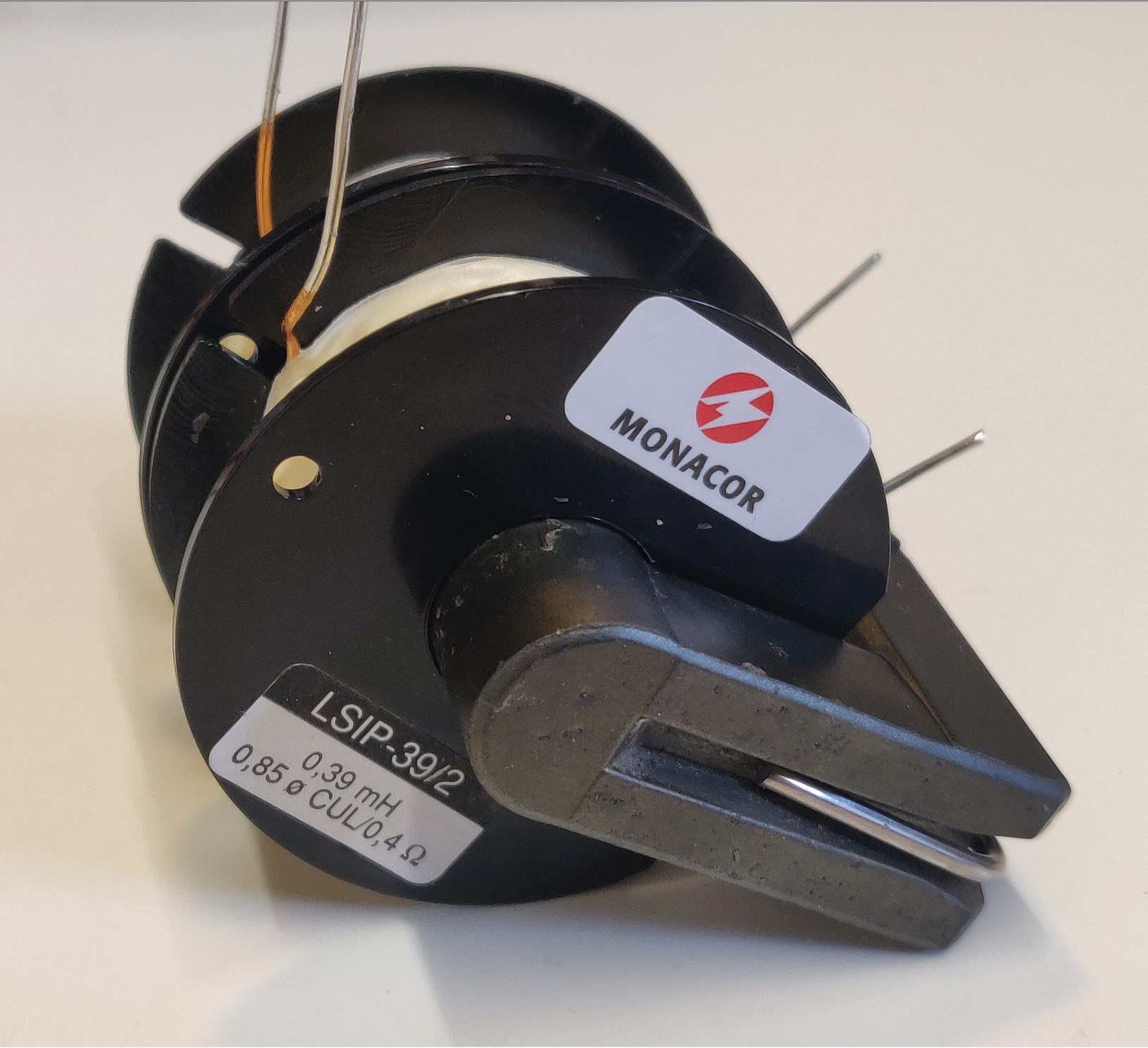
I was not able to get any clear results with the store purchased coils I had, going through all the configurations, the linear drop was still missing and the coils didn't seem to react well together no matter what configuration I used.

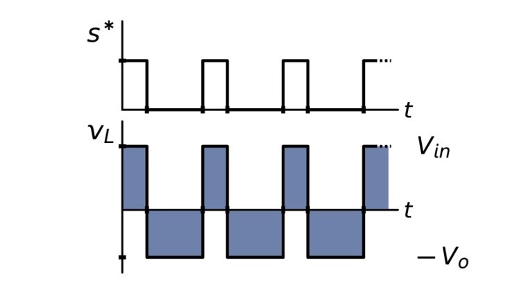
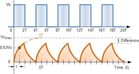
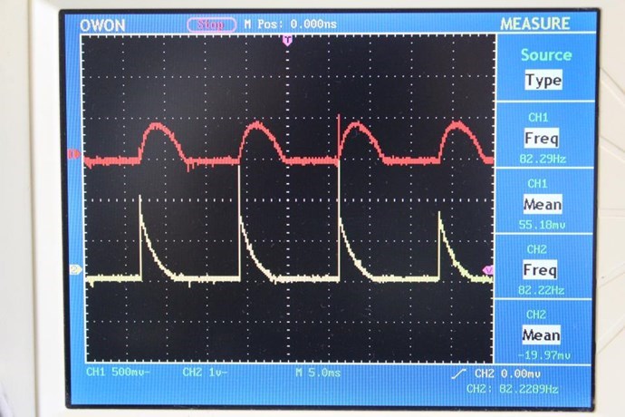
After watching one of Akula tear down videos I noticed he had gapped his core when he pulled the halves apart, the gap material fell out. So I tried that and noticed that the scope trace over the coil being pulsed finally showed a linear drop. However, the response from the other coil dropped dramatically. No size gap seemed to fix the issues.

So, thinking about Chris's original experiment, the coils used were actually shorter. Meaning there were two coils and an empty bobbin on one side of the core. My bobbins only allowed room for two. Which put them on opposite sides of the gap. So to explore this I wound more coils. This time each coil took up the whole side of the core.

This also gave no good clear results, gapped or not.

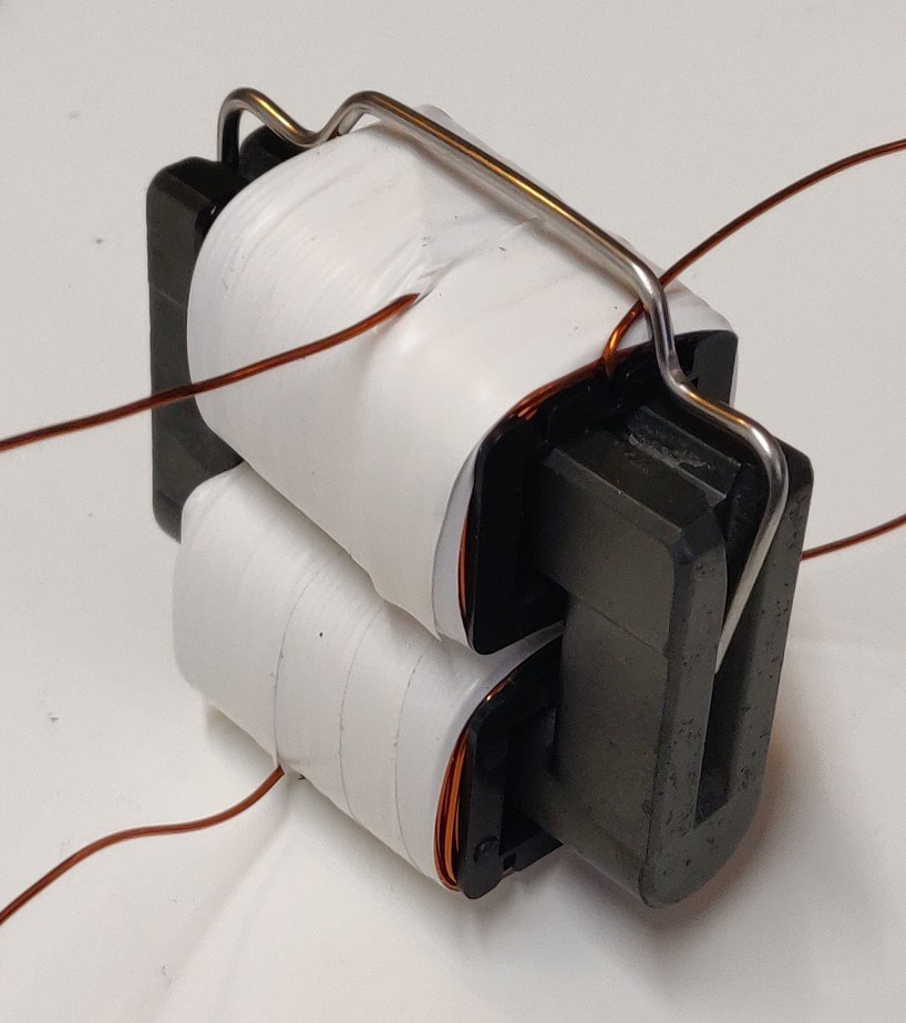
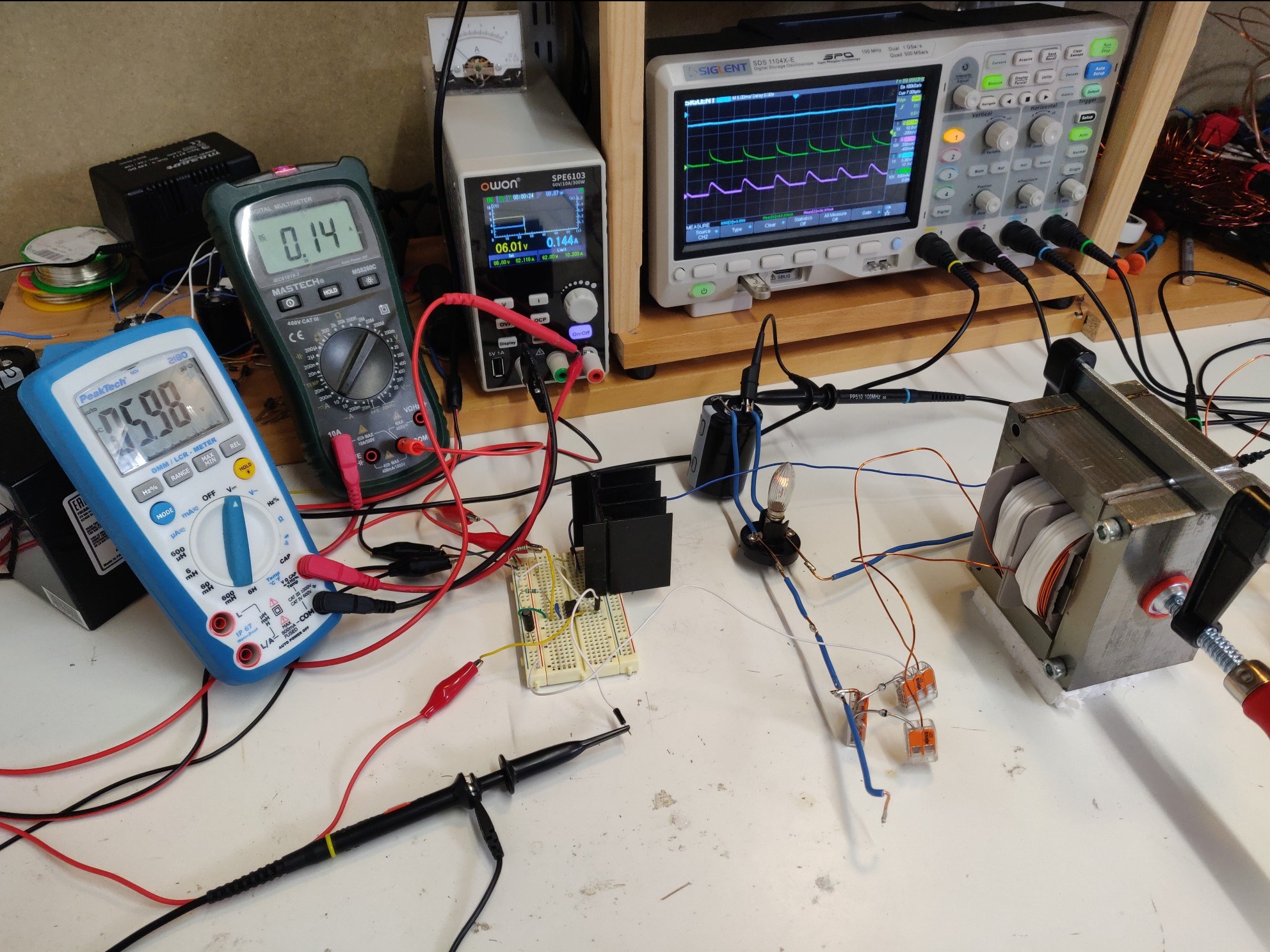
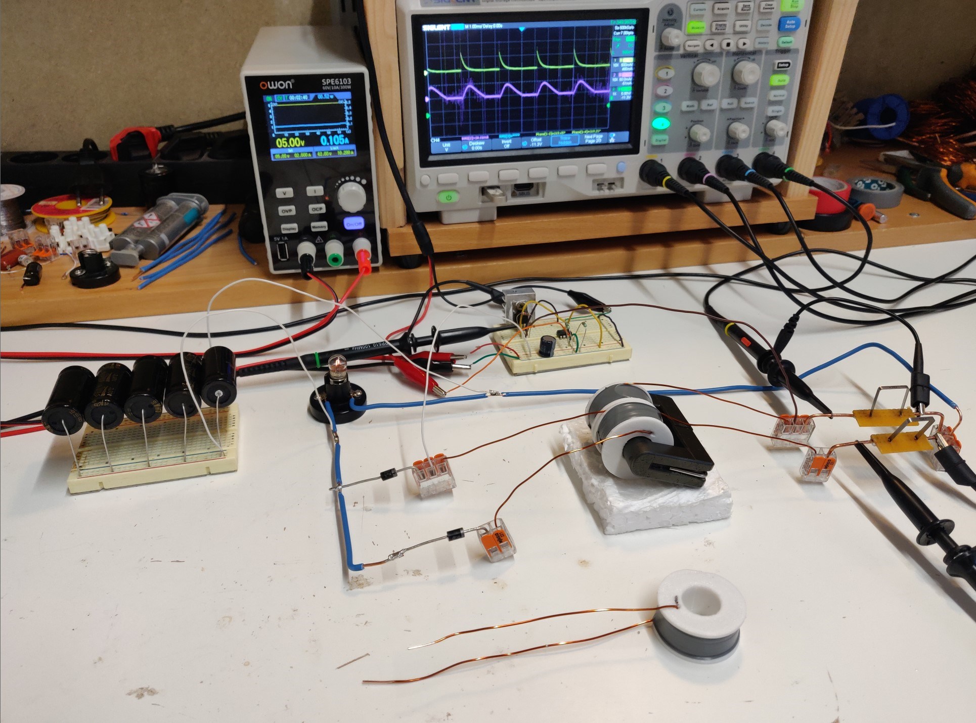
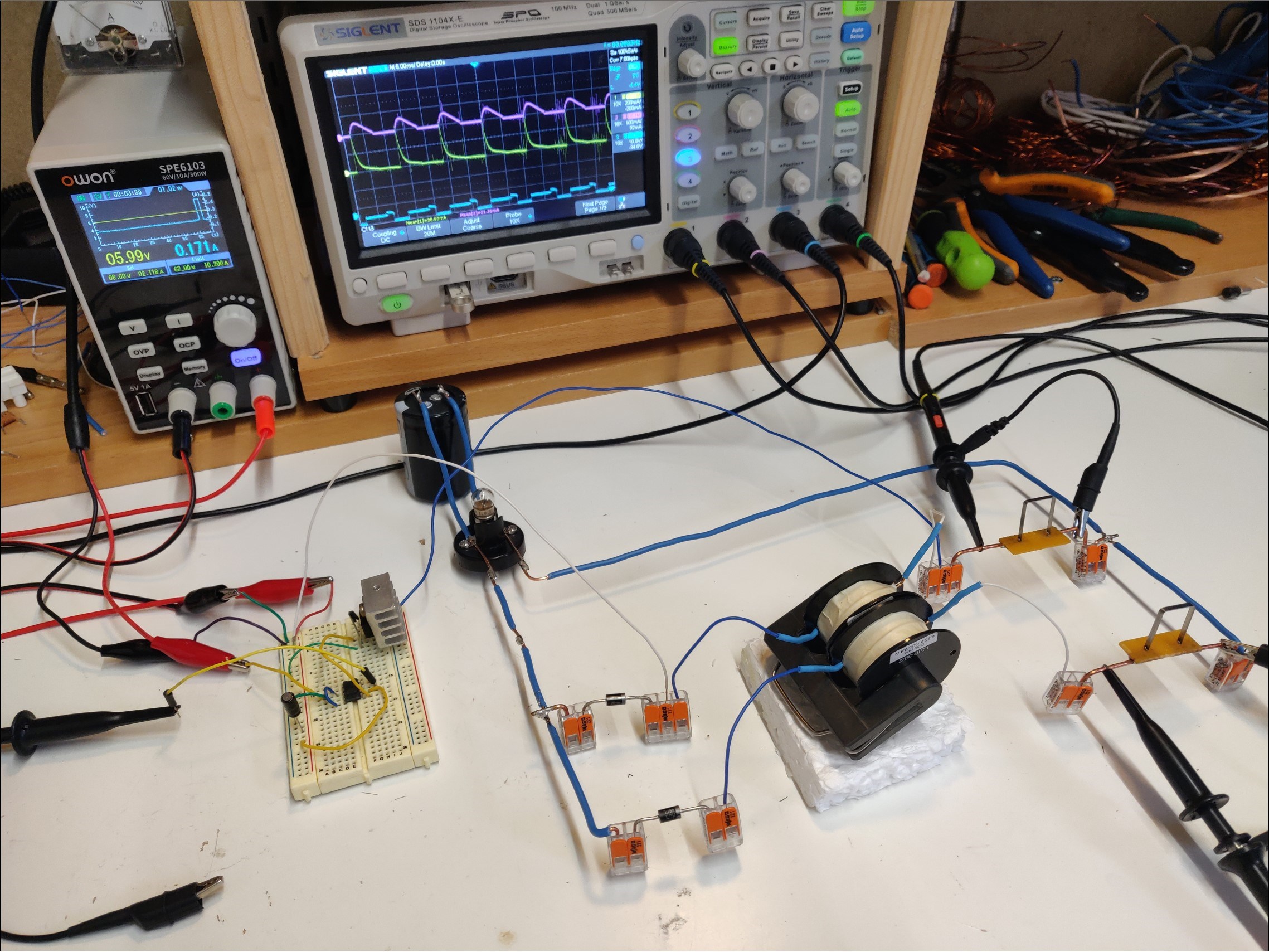
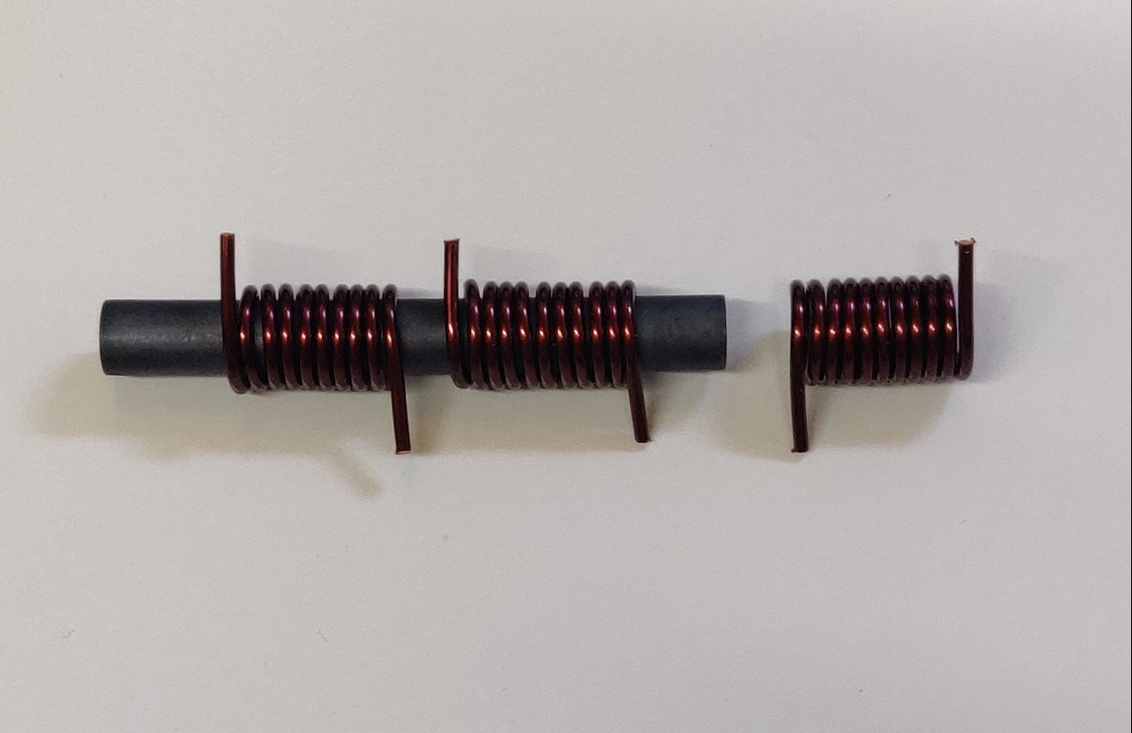
So I retried everything with several different loads, and a bit more load seemed to help. I then decided to again, wind some new coils and use the microwave oven core that I have. This gave the best results out of everything I've tried. Still not as clear as Chris's original experiment, but the suggested observations can be made. Here is the new setup.

All coils are about 75 turns of 0.8mm wire, at about 0.53 mH, give or take a little.

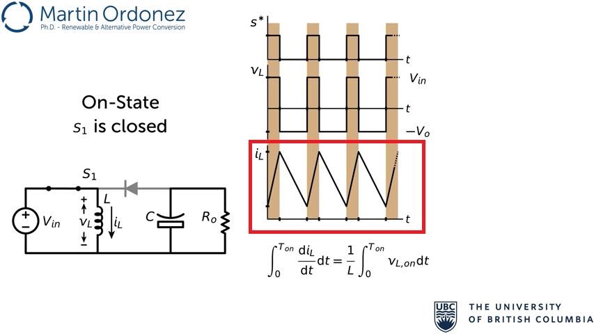
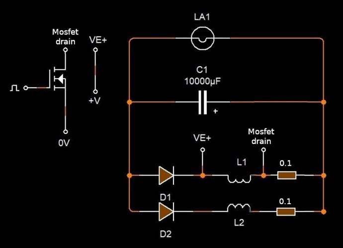
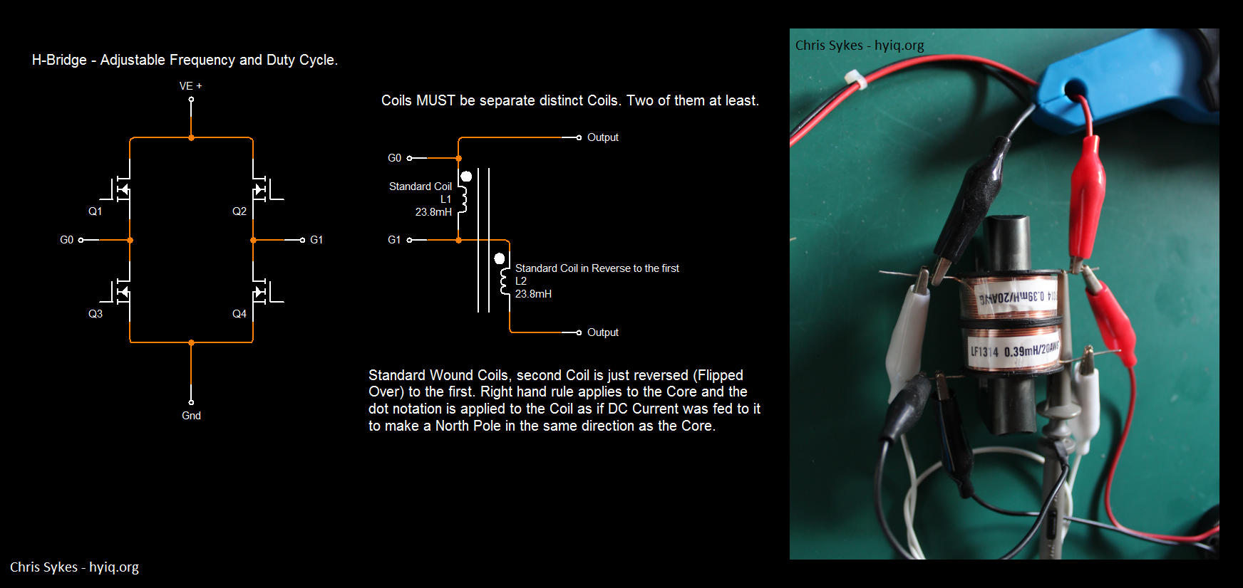
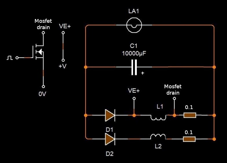
The circuit is still the same.

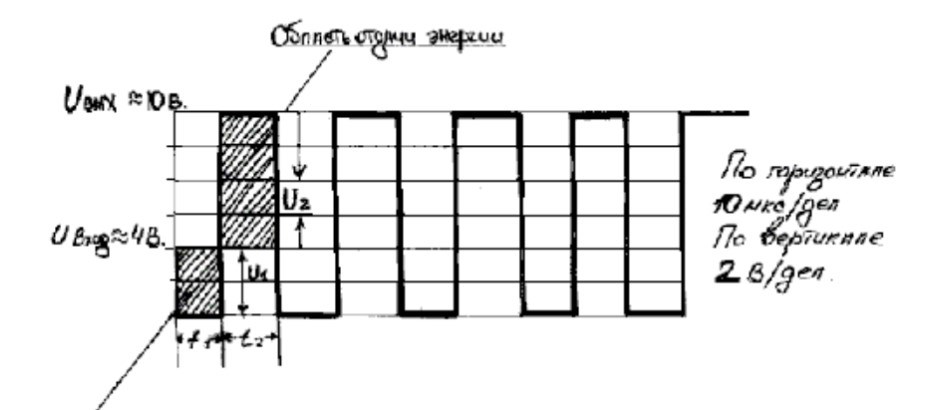
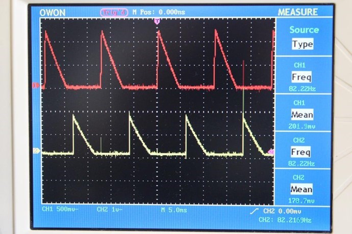
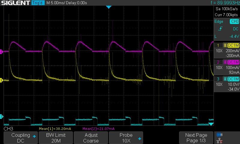
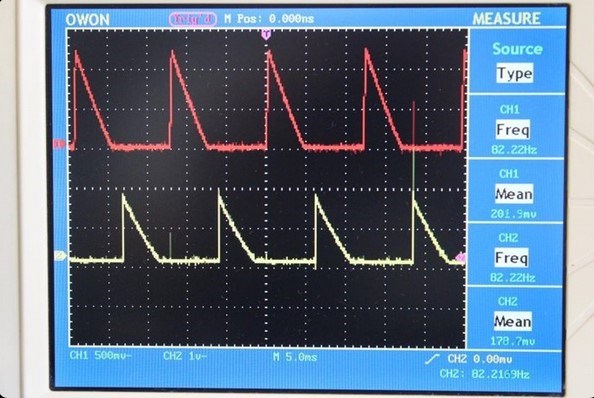
This time I'm pulsing with 6V because I thought the waveforms were getting screwy looking up at 10V. Core saturation? I'm guessing not, but something was amiss.

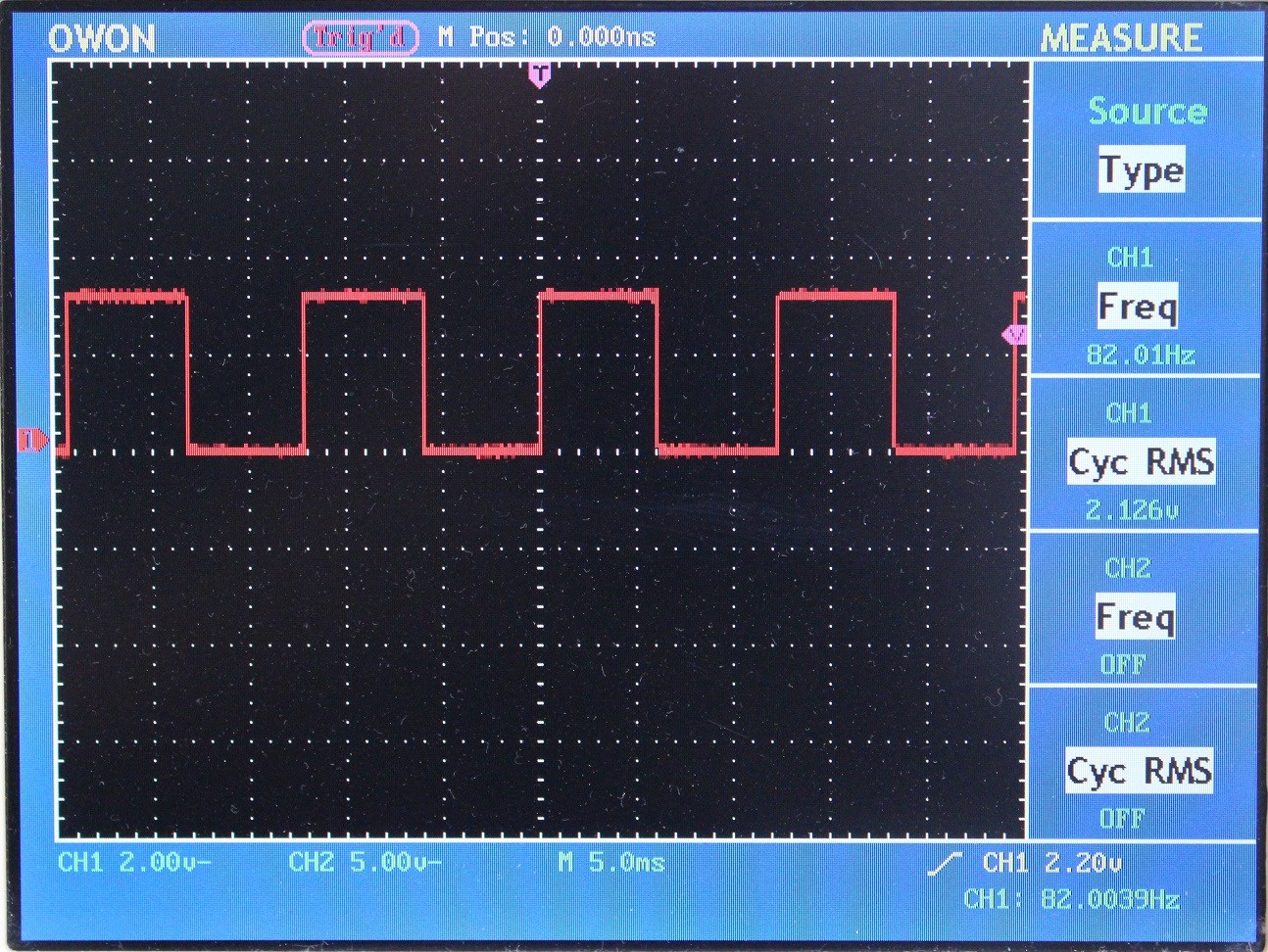
Still 90 Hz, 50% duty cycle for all tests.

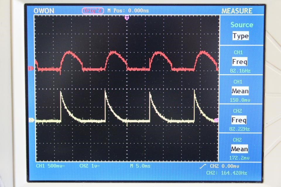
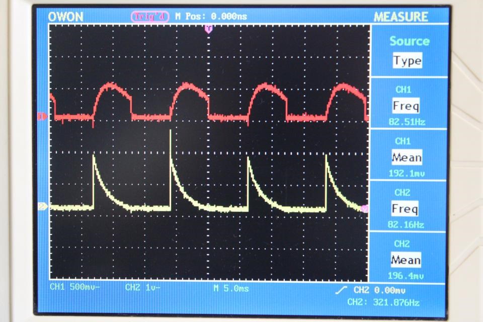
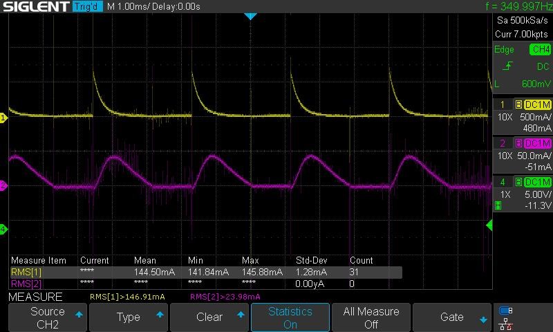
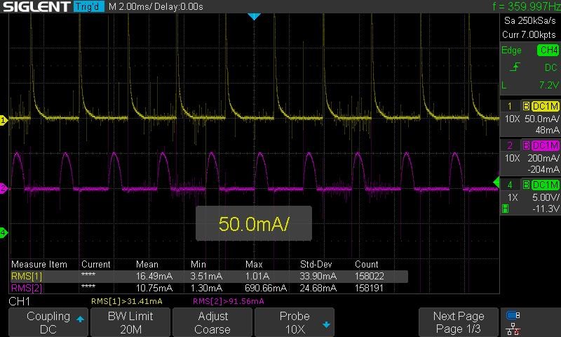
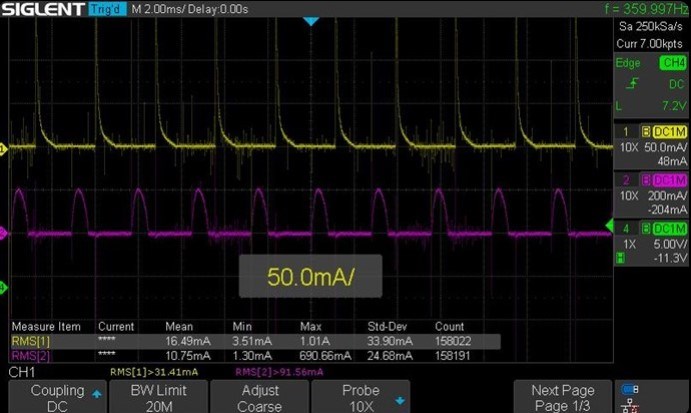
So here are the results:

L1, green trace, is the coil being pulsed.

L2, purple trace, is the coil being changed.

Blue trace is cap voltage.

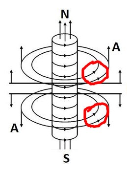
Bucking does not Work: config 1 polarity 1 (identical coils same direction)

Vcap: 3.43
PS: 5.98 V 140 mA
L1: 61.26 mA
L2: 27.60 mA


Bucking does not Work: config 1 polarity 2 coil spun around core 180')

Vcap: 3.71
PS: 5.98 V 150 mA
L1: 85.20 mA
L2: 10.35 mA


Bucking does Work: config 1 polarity 1 (coil flipped on core, and spun 180')

Vcap: 3.45
PS: 5.98 V 145 mA
L1: 63.53 mA
L2: 26.46 mA

Bucking does Work: config 1 polarity 2 (last config, coil spun 180' around core again)
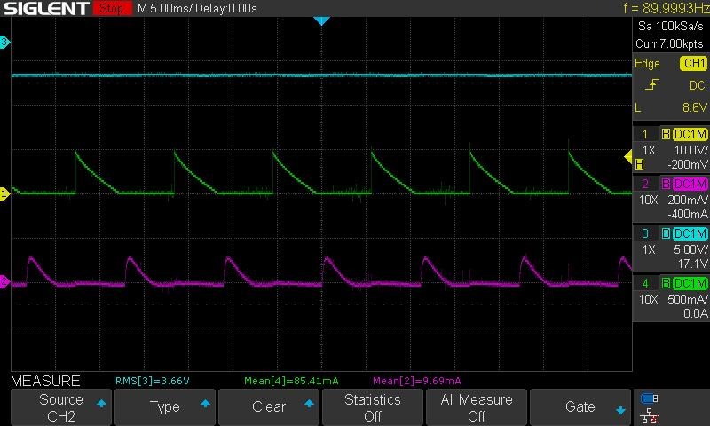
Vcap: 3.66
PS: 5.98 V 150 mA
L1: 85.41 mA
L2: 9.69 mA


Bucking does Work: config 2 polarity 1 (cw ccw coils, traditional bucking directions)

Vcap: 3.46
PS: 5.98 V 140 mA
L1: 61.90 mA
L2: 28.57 mA


Bucking does Work: config 2 polarity 2 (coil spun around core 180')

Vcap: 3.71
PS: 5.98 V 150 mA
L1: 86.44 mA
L2: 6.20 mA


Conclusions and whatnot:

So the waveforms were not as perfect as seen in the original experiment, but it still seems to work. The observations, to my understanding, were to be the configurations which allowed for more output without additional input, and at the same time see the most interactions between the coils.

Indeed the best one is Bucking does Work: config 2 polarity 1 (cw ccw coils, traditional bucking directions), with a second place of Bucking does Work: config 1 polarity 1 (coil flipped on core, and spun 180').

I will leave this for now. I'm sure I'll want to edit this, but I'm out of time, so I just want to get the results up. I do intend to make one more post with some questions. Hopefully I can get to it tomorrow, otherwise early next week.

Again, learned a lot messing around experimenting. Thanks!

Marcel


Chris posted this 4 weeks ago

Hey Marcel,

As always, good work Marcel!

The original Experiment proves what I was always told, was not true: "Two Coils on a Core will operate the same no matter how they are Wound"

You can see, the way the Coils are Wound and used, can make a difference!

In my Scope shots: Here

For those following, we see some very interesting results for the Current Wave Forms...


Remember, Current is the Magnetic Field, Changing in Time!


The base Frequency and the Duty Cycle was not changed during my experiments!

  • 82.29 Hz
  • 50% Duty Cycle.

So, in an Electronic Circuit, the Applied Voltage is something like this:


However, we see a big difference between the Time Constants in the Coil Configurations! A massive difference in point of fact!

A typical Time Constant looks something like this:


Where:

  • Blue Trace is the Applied Voltage across the Inductor.
  • Brown is the Current, Ramping up as the Voltage Applied (On), and Current Ramps down as Voltage is not Applied (Off). This is where we normally see a Voltage Spike: Flyback. We see this Ramp Down on the Yellow Wave Form.


From fastest to slowest:


Note: Red Trace is the Current Trace we are looking at. 

Bucking does not Work - Experiment:

This experiment investigates two identical Coils, both in the same winding direction relative to the Core, utilising both Polarity's on one Coil only (Closest to the reader):


Bucking does Work - Cfg One - Experiment

This experiment investigates two identical Coils, one Coil flipped over relative to the Core, utilising both Polarity's on one Coil only (Closest to the reader):


Bucking does Work - Cfg Two - Experiment

This experiment investigates two identical Coils, one Coil wound Clockwise relative to the Core and the other Coil is wound Counter Clockwise relative to the Core, utilising both Polarity's on one Coil only (Closest to the reader):


In this last scope Shot, Cfg Two, we can see that the Current is still High and the Switching is kicking back in again! You can see, the Generation of Electrical Energy, by Opposing Coil Configurations, is cut off by the Switching back in of the Applied Voltage, at a 50% Duty Cycle.


  • This is a super important fact to see! It is critical to understand the importance here!


  • This is all occurring with absolutely no cost on the Input, the Input is not affected, loaded, in anyway at all here!!! 


So, a way to keep the Electromagnetic Induction going longer, is to reduce the Duty Cycle. Down, shorter in time, so there is more Off Time, and the Coils can Interact together, over a longer time.

Don't forget, Voltage is the Number of Turns (N) in the Proximity of a Changing Magnetic Field. E.M.F = -NdPhi/dt

   Chris


This is the most important post in the thread, it proves a Gain in operation can be made by simply winding the Coils the way I have shown, something everyone I talked to, said was impossible! I have spoken to Electrical Engineers with decades of experience and they said it was impossible, well I have shown the impossible right there, very simple experiment that proves conventional science to be incomplete!

This should be common knowledge, its not, its not known at all for the most part!


You should be astonished by the results of this thread!

You should, but most researchers ignore the important stuff, that's why so many come here to learn what everyone else has missed!

Everyone comes here to learn and watch the progress we are making and have made!

What does this experiment prove? What does the Coil see that's different when wound in this direction?


Ponder that, because its important!

Keep up the excellent work Marcel, its very important others see the progress we are making, to push the River!

Best Wishes,

   Chris

FringeIdeas posted this 3 weeks ago

Hey Christ, thanks!

Your question:

What does this experiment prove? What does the Coil see that's different when wound in this direction?

Aside from the different configurations yielding different output results, at the beginning of your experiment thread, Some Coils Buck and some Coils DONT,  you mentioned the A vector potential. If I'm not mistaken, this has everything to do with your question.

There are several videos and threads that discuss this. Right now I'm kind of poking at the hyiq.org page A Vector Potential

There was one video, which I can't seem to remember which one at the moment, where you are going through a dozen examples in nature, of vortexes. And I can imagine that if this A vector potential is a vortex, yes a real field and not just a mathematical way of looking at magnetic fields, then the spin, the vortex, is going to interact differently with different coil configurations. Magnitude of the field being stronger near the center, polarities mattering, etc.

With that said, I have a lot of reading and thinking to do. I'm having trouble visualizing how the spin, or vortex, would look like in a multi layer coil. I've also messed myself up and realized I have no idea how a voltage is induced on a secondary coil. I thought the voltage was an excess of electrons on one end, creating a pressure, which results in current. But then how could an induced voltage be there in a secondary coil before any current runs... Lots of thinking to do.

I would like to start with one question though. A magnetic field in motion creates the A vector potential. The magnetic flux is completely pulled into the transformer core, and the A vector is left on the outside of the core. Does this A vector still have any attraction too, or is bound to the core in any way? For example in the non-inductive coil experiment, the coils are on opposite sides of the C core(s). Is the A vector traveling around the core to interact with the second coil? Or is the A vector interacting straight across the space to the second coil?

As always, much appreciated!

Marcel

  • Liked by
  • Augenblick
  • Chris
FringeIdeas posted this 3 weeks ago

Ok, so I may have answered my own questions.

My question about the A vector potential being bound to the core, etc.

Does this A vector still have any attraction too, or is bound to the core in any way? For example in the non-inductive coil experiment, the coils are on opposite sides of the C core(s). Is the A vector traveling around the core to interact with the second coil? Or is the A vector interacting straight across the space to the second coil?

I think it's safe to say from the model itself that the A vector follows the magnetic field Φ. So yes it would traverse around the core, but only because Φ is taking that path.

Second question, about the induced voltage on a secondary coil.

I've also messed myself up and realized I have no idea how a voltage is induced on a secondary coil. I thought the voltage was an excess of electrons on one end, creating a pressure, which results in current. But then how could an induced voltage be there in a secondary coil before any current runs...

I think the term "charge separation" throws me off. But am I correct to say the A vector potential IS the EMF? It IS the pressure on the electrons as it traverses the secondary coil?

I've been re-watching this video a few times now, just thinking.

Which I believe is what led me to this thread. Connecting the dots to Energy - The A-Field

So yeah, I think before moving on to anymore experiments I need to spend a little time thinking some of this stuff over and trying to really get a good mental visualization of what is actually going on.

Thanks!

Marcel

  • Liked by
  • Augenblick
  • Chris
Classic posted this 3 weeks ago

Hello everyone,


I don’t want to confuse anyone, but from my understanding of phenomena all is about currents running against each other.

I have studied quite a fair amount of patents and I found out many similarities of how amplifying is done and why it is possible (against mainstream science teachings). Mostly mainstream science fail to account for total amount of energy input in a system, mainly because of their utterly nonsensical denial of aether existence.


I have seen many fail to power their coils or being able to extract any extra power but, they don’t understand Inductance, Capacitance and Impedance and why all these 3 components depend on amplitude (voltage) and frequency of oscillations, or why it is important to reach same resonance between 2 circuits (harmonic resonance) or what is resonance. Also, understanding of standing waves, how they are triggered, what they do and how to collect them.


One must understand beforehand that the frequency will be set by the length of wire used to make the coil and its length should always be calculated as 1/2 or respective 1/4 of the wavelength for tuning purpose as RLC circuit. I recommend wikipedia 1/4 wave amplification reading.


So, amplification can be obtained by 2 methods:

  1. Bucking coils
  2. Standing waves


  1. Bucking coils. This means when first coil (POC1) is powered introduce EMF in second coil (POC2) when an impulse is applied, time on. When time off comes, magnetic field collapse in both coils (POC1 and POC2) and in the same time second coil (POC2) is powered, time on. This is half cycle described only !

What this means ? BEMF from POC1 will take place in the same time with EMF from POC2. If we look only on electric component we can not understand what is happening as the picture is not complete and we need to look at magnetic component which always will affect both POC1 and POC2 in the same time, while electric component is acting only in one coil at a time with zero resistance if they are tuned for resonance.

2. Standing waves. First of all, coils must be tuned almost perfect for resonance and wire length MUST be exact length to match 1/2 multiple of wavelength of frequency and the higher is the frequency the higher is the accuracy in build required. If not, standing waves will not match collection points at ends of wires and while we still have standing waves in circuit, all beneficial effects will be nullified and results will be almost destructive.

Tunning for resonance is compulsory and should be calculated for RLC circuit even if we don’t use resistors we must take in account wire resistance as a dampening effect.


Inductance is telling us how much energy is stored in magnetic field ! If the energy stored there is very small, frequency of transfer must be be very high to see any results

Capacitance is telling us how much energy can be stored in electric field and this should be accounted for coil capacitance plus capacitors used for tuning.

I think it is obvious that Inductance and capacitance must be correlated. 
Resistance should be used as element of stiff (damping element) when length of wire need to be adjusted for resonance and adding resistors in parallel or series should be done upon resonant frequency. The higher is resistance the higher will go frequency

Always keep in mind RLC calculus !


Also, coil 1 must have same resonant frequency as coil 2+3, length of wire of coil 1 must be equal with length of wire coil 2+3 to allow 100% of energy transfer, even if coil 2 and coil 3 will have different number of turns.

FringeIdeas posted this 3 weeks ago

Hey Classic,

While I would agree with a lot of what you say, the point of this experiment, which was always meant to be under unity and really had nothing to do with resonance of any kind, was to examine the fact that the winding directions imapct the output, and to think about why this is, as the normal EE guy would say it winding direction doesn't matter.

If you have any thoughts on the A vector potential, or other ideas of why the winding direction matters, I'd love to chat about that though. Vortex in the aether.. sounds beautiful.

Thanks you,

Marcel

Classic posted this 3 weeks ago

@FringeIdeas, i am not sure anymore if winding direction really makes any difference. I mean not the winding direction alone without considering positive and negative connections.


A bifilar coil can be considered bucking coils depending on how coil ends are connected, which polarity goes where. For example if 2 capacitors of equal value are inserted in series between 2 coils the effect will be 180 degree phase shift, if 2 capacitors where one of them is double capacity of the first phased shift is 135 degree. Please see Arie Melis DeGeus patents and his books Quantum Fluids Universalis and especially his cyclotron and NL1032750 regarding 2 currents running against each other in adiacent wires.


In my opinion the break in windings is the most important which I think is the method of creating impulses and winding directions is somehow less important.


Also we can observe that if we have 2 coils and we energise one of them according to right hand rule magnetic flux will follow one direction while in second (induced) coil polarity will be in reverse and it really doesn’t matter if these 2 coils are arranged on a square core frame each coils with its core or being wounded on top of each other on a single core.


Best description that I ever seen how currents running in coils is in Daniel Macfarland Cook batteries, where the inventor describe 8 currents running in 4 coils in the same time, and each coil will have a EMF and BEMF of different intensities in the same time as long as they have enough self inductance (length of wires) and corresponding ferromagnetic core to sustain the transfer of energy between coils.


I prefer to keep everything as simple as possible and avoid as much as I can explanations of mainstream science with ridiculous nonsensical terms (sometimes).


If someone can understand what a permanent magnet is, then the key of obtaining unlimited electric energy is in their hands.The difference between a permanent magnet and electro magnet consist of of their abilities and capabilities to retain an electric charge or not. Magnetic field is a consequence of electric field.


I really am pissed off of why mainstream science avoid at any cost to explain permanent magnets and keep focusing on anything else. A permanent magnet is a self resonant self induced device and a simple alloy of iron, copper, nickel will remain a simple alloy without electric charge placed in it. Once electric charge is placed in such alloy ONCE, will perform continuous work (magnetic force)for as long as electric charge is present. When they lose electric charge they become a simple alloy, but we can re apply electric charge and they start working again.

Electric charge is really circulating in a permanent magnet with no chance to escape the compound due to low and high resistance of copper and nickel while iron if the amplification factor of magnetic field. There is a gradient in resistance which is exploited, this gradient create a potential difference in electric charge which is in every atomic structure and we can break a permanent magnet down to atomic structure pieces and every single pieces containing iron, copper, nickel will have the same performance.


I can go on for long with mechanical capabilities and interactions in a permanent magnet, chemical etc to explain further but it will diverge from the topic.


So, that’s why I am not sure anymore if winding direction makes a real difference compared with method of connections of polarities. In electro magnets (coils) we combine only 2 elements: copper and iron and their mass and geometry will influence and enhance the effect we seek: electric or magnetic or both. If we seek to transfer energy from one coil to another coil or many more coils we need to make sure all secondary (induced) coils are placed in the same magnetic field created by the primary.

  • Liked by
  • Augenblick
Classic posted this 3 weeks ago

I just checked on my setup if winding direction may influence the output or input drain and guess what ? If there is any difference I can not notice it.

 If you look at my bifilar spiral flat coils I can flip them and nothing changes, but connections makes all the difference.

  • Liked by
  • Augenblick
FringeIdeas posted this 3 weeks ago

@Classic, ok thanks for checking, and noted.

@Chris, if you could please tell me if I'm on track or not, as I'm still trying to wrap my head around this A vector potential spin.

This picture, I could not help but notice the spin of both polarities is in the same direction.

So in my head I started thinking (potential rabbit hole) how it would be awesome to engineer a way to get two opposing coils to have spin in the same direction, adding to eachother's spin, and possibly being able to just tap the spin and keep it spinning. If that makes sense. Steven Marks and the gyroscopic effect came to mind. BUT, I think I'm wrong.

You have the youtube video Self Assisted Oscillation or Field Effect Amplification of an Induced Rotating Magnetic Field

The coils are cw/ccw so I assume the spins are actually in opposite direction. Also with Floyd Sweet he states:

When the current in one half of the conductors in the coils (i.e., one of the bifilar elements in each coil) of the device is moving up, both the current and the magnetic field follow the right-hand rule.

The resultant motional E-field would be vertical to both and inwardly directed.

At the same time the current in the other half of the conductors in the coils is moving down and both the current and magnetic field follow the right-hand rule.

The resulting motional E-field is again vertical to both and inwardly directed.

When he says inwardly directed he does mean the E fiields are directed toward eachother, so the spins would also be in opposite direction (correct me if I'm wrong).

So in the thread Connecting the dots to Energy - The A-Field you state 

A is the Electric Field with Curl, two equal and opposite ∇ + -∇ = 0, the Curl cancels via Superposition and we get a Straight Electric Field, Ä€.

So, what we are dealing with is actually.. during the standing wave condition, the superposition of E fields adding, from E/2 to E, with the spins opposing, cancelling, leaving us with the un-curled A vector potential that Sweet and Bearden talk about.

But, I'm still at a loss at how this could have any kind of directional bias, for example creating a condition where a rotating magnetic field is possible. It would seem to me that we would have a non-directional "surging magnetic field" and Floyd Sweet calls it. In the un-curled state, is it directional or not? I'm stepping over something again

As always, appreciate the help.

Marcel

Edit: And almost forgot. I was going to venture next to the thread YoElMiCrO's Ferro-Magnetic Resonance, and experiment there a bit. But are there any other experiments that you think might be more beneficial for understanding this A field better? Thanks again!


Chris posted this 3 weeks ago

Hey Marcel,

In my humble opinion, I believe you are 100% on target! My Research and experiments give me the exact same conclusions, and we can make use of this knowledge to make improvements in our Energy Machines!

Best Wishes,

   Chris

We're Light Years Ahead!
Members Online:

No one online at the moment


What is a Scalar:

In physics, scalars are physical quantities that are unaffected by changes to a vector space basis. Scalars are often accompanied by units of measurement, as in "10 cm". Examples of scalar quantities are mass, distance, charge, volume, time, speed, and the magnitude of physical vectors in general.

You need to forget the Non-Sense that some spout with out knowing the actual Definition of the word Scalar! Some people talk absolute Bull Sh*t!

The pressure P in the formula P = pgh, pgh is a scalar that tells you the amount of this squashing force per unit area in a fluid.

A Scalar, having both direction and magnitude, can be anything! The Magnetic Field, a Charge moving, yet some Numb Nuts think it means Magic Science!

Message from God:

Hello my children. This is Yahweh, the one true Lord. You have found creation's secret. Now share it peacefully with the world.

Ref: Message from God written inside the Human Genome

God be in my head, and in my thinking.

God be in my eyes, and in my looking.

God be in my mouth, and in my speaking.

Oh, God be in my heart, and in my understanding.

Your Support:

More than anything else, your contributions to this forum are most important! We are trying to actively get all visitors involved, but we do only have a few main contributors, which are very much appreciated! If you would like to see more pages with more detailed experiments and answers, perhaps a contribution of another type maybe possible:

PayPal De-Platformed me!

They REFUSE to tell me why!

We now use Wise!

Donate
Use E-Mail: Chris at aboveunity.com

The content I am sharing is not only unique, but is changing the world as we know it! Please Support Us!

Thank You So Much!

Weeks High Earners:
The great Nikola Tesla:

Ere many generations pass, our machinery will be driven by a power obtainable at any point of the universe. This idea is not novel. Men have been led to it long ago by instinct or reason. It has been expressed in many ways, and in many places, in the history of old and new. We find it in the delightful myth of Antheus, who drives power from the earth; we find it among the subtle speculations of one of your splendid mathematicians, and in many hints and statements of thinkers of the present time. Throughout space there is energy. Is this energy static or kinetic? If static, our hopes are in vain; if kinetic - and this we know it is for certain - then it is a mere question of time when men will succeed in attaching their machinery to the very wheelwork of nature.

Experiments With Alternate Currents Of High Potential And High Frequency (February 1892).

Close