FringeIdeas Non-Inductive Coil Experiment Replication

  • 4.8K Views
  • Last Post 20 February 2025
FringeIdeas posted this 07 May 2023

I'll start this thread more or less for my documentation and a bit of questioning. I've been reading a ton and going over the videos several times. However, I'm pretty sure I don't have this correct yet. And I'm pretty sure I'm starting to confuse myself. 🙂

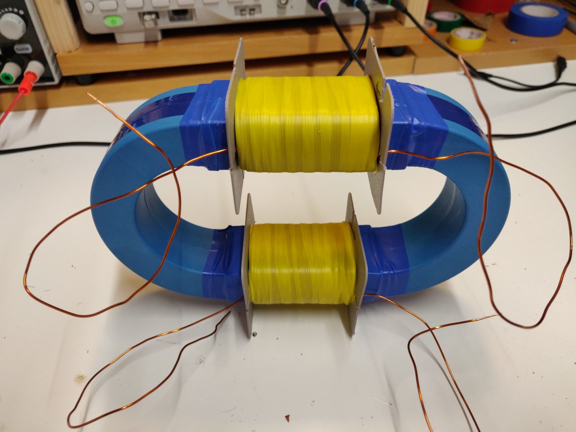
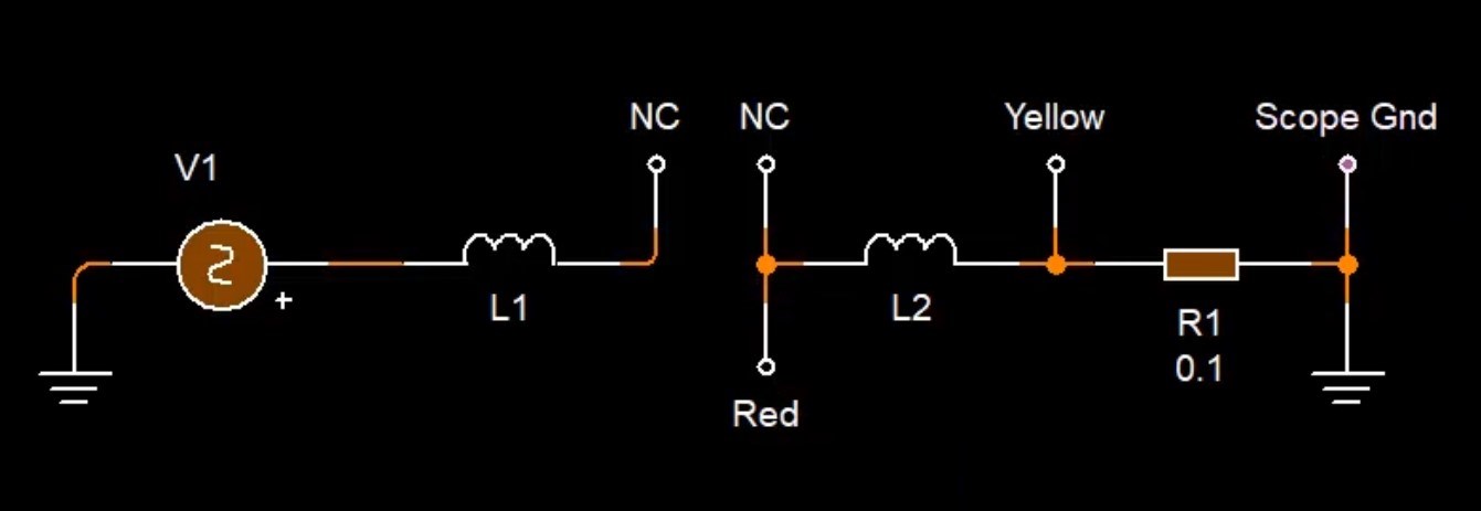
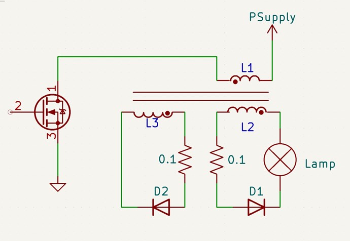
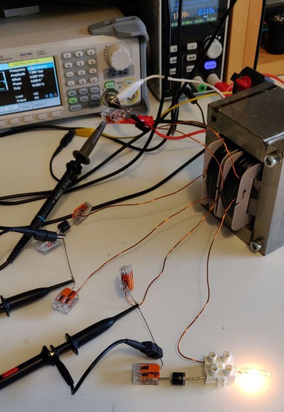
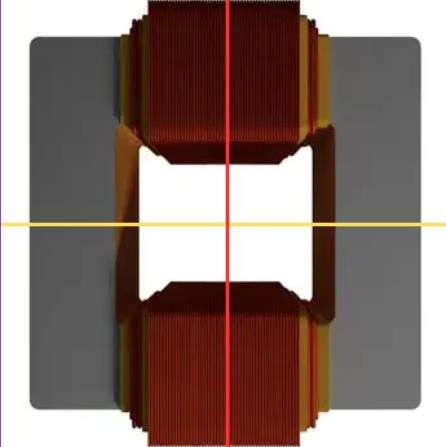
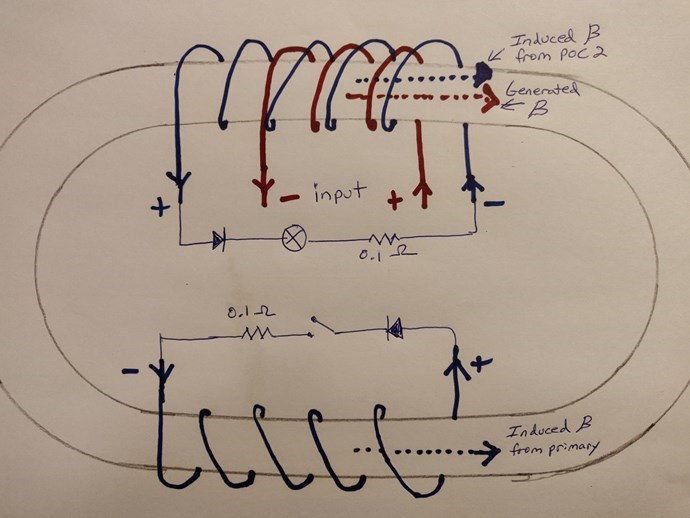
L1 is the input, 20 turns clockwise of 0.8mm wire. It's wrapped over, the same direction clockwise, mutually inductive, to L2, which is 140 turns of 0.8mm wire. L3 is next to these, also 140 turns of 0.8mm wire, but wrapped counter clockwise. The lamp is on L2.

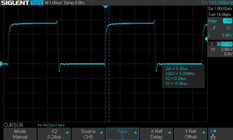
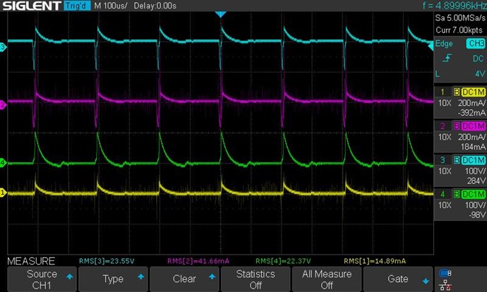
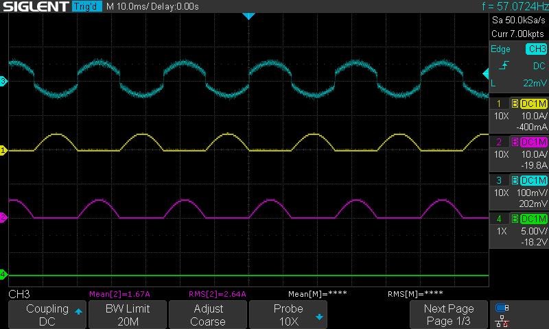
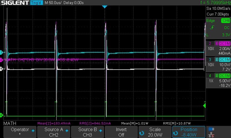
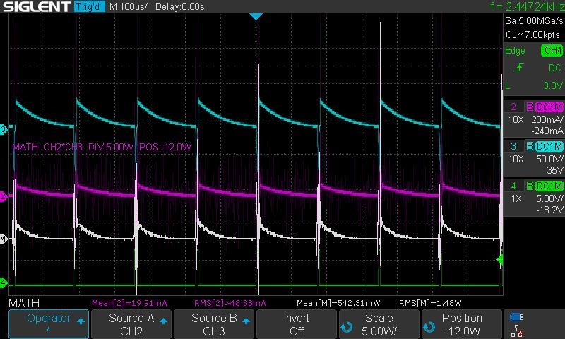
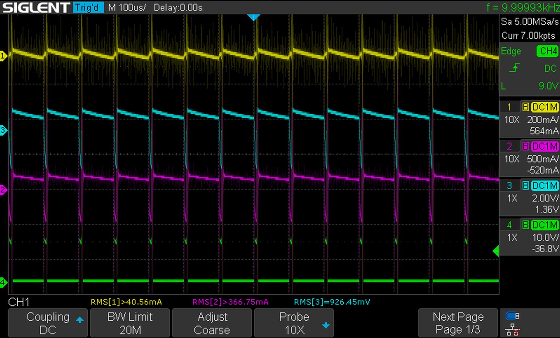
The pictures were taken at about 5.6 KHz, nevermind what the scope screenshot says, the counter was all over the place. I'm pulsing 12v from a power supply at 10% duty cycle. Yellow and purple traces are L2 and L3. L1 voltage is the blue trace.

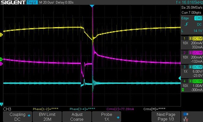
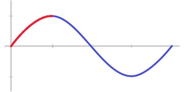
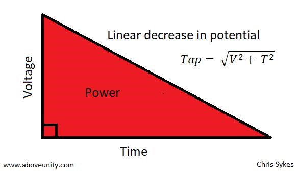
The core makes horribly loud 8-bit video game music while I'm messing with frequency ranges, so I assume some bucking is taking place. But the scope shot doesn't look right, not sawtooth enough. I noticed comments on Madscientist's recent experiments about polarities and the exponential curve instead of sawtooth, but I believe I have my diodes correct. Still, not really seeing magnetic resonance I think.

Correct me here, I'm wrong somewhere I'm sure. The input coil raises the magnetic field, north pole to the left side as it's wound clockwise from the right. Current flows in L2, the same direction, and when L1 is turned off, what is left is the magnetic field which will want to collapse and create current the opposite direction, creating a north to the right side. But then the diode is wrong, as it would be blocking the current from the collapse. UNLESS, we see a flip of current polarity because of the magnetic resonance, Mr Preva. In that case, then we have the currents, and magnetic fields from L2 and L3 opposing, and we should see the sawtooth waveform. But I was under the, possibly ignorant, impression that the Mr Preva experiment worked because of the mismatch of coil turns, 7 to 11 I believe it was. But on these coils we want matching turns, in my case 140 to 140 turns, correct? Because we want matching magnetic fields when loads are applied, for a maximum fight against each other. Again, correct me if I'm wrong please.

So, again, I think I might be seeing a tiny bit of magnetic resonance, but not enough. I need to pick up a few new printed bobbins from a friend this week, but I will increase the turns on L2 and L3 to bring up the magnetic fields, maybe 200 or 250 turns to start. Also, I'll try to increase turns on L1 so more magnetic field is delivered. Maybe overdo that too a bit, so I can walk it down a few turns at a time to see what is best. In the meantime, any advice or pointers would be completely acceptable. 🙂

I'll update more soon. And this has been fun getting back to research, so thanks to everyone that has contributed.

Marcel


Order By: Standard | Newest | Votes
Chris posted this 20 February 2025

Hey Marcel,

Thats beautiful! Thanks for sharing!

This is a very valuable experiment! You can experiment with Open Cores, High Reluctance, No Cores, with the same Reluctance, and even use a C Core to close the Gap and reduce the Reluctance.

With Iron Laminate cores, the Frequency will need to be lower, but this is obvious!

I will share more with you soon!

Best Wishes,

   Chris

FringeIdeas posted this 18 February 2025

Chris! Here is a build update.

I was going to say that mine looks better than yours, but my 3mm 3d print started bulging a bit toward the end and the winding got a little out of control.. You got lucky.

So this is just a replication of what Chris had shown here, and later posts, https://www.aboveunity.com/thread/non-inductive-experiment/?order=all#comment-f5bd3052-e3a8-44e2-a463-b1fd00174a5a

I liked the gap and the large cross sectional area, and I have to start learning about what the magnets contribute to these machines, so I decided to at least start putting together this build for future experiments. Here are the specs:

  • 0.8 mm wire, each coil is 250 turns, CW and CCW wound.
  • 3 mm gap in between the coils.
  • 3 mm gap between each magnet and its adjacent coil.
  • CSA is about 54 mm x 105 mm.
  • Coils length is about 14 mm or so.
  • Magnets are 150x102x12 mm (I also have a few 150x102x25 mm magnets).
  • The core material is taken from a microwave oven transformer, hacked to pieces.
  • No input coil yet.

Here are a few pictures.


I still need to epoxy a few things together but it turned out quite nice I would say.

And like I said, this was just a build update. I don't plan on diving into this just yet, as there are a few things I'm still playing with over in the Melnicheko thread, in which I'll probably post some experiments soon. But I will get back to this as soon as I can, as well as the few loose ends that I still have in this thread. The wife took the kids on a short vacation to see family, so for the rest of the week I should be able to get some experiments done. Let's see.

Marcel

FringeIdeas posted this 05 December 2024

Hey,

So I've now become mentally comfortable with my setup and how my input coil opposes L3, not L2 on which it is wrapped. I was reading one of ISLab's threads and found a post by raivope which was quite interesting. Here

I'll just leave it at that. Thank you raivope for putting thoughts to keyboard.

And for now, I'll detour from this thread for a bit, to work on some Melnichenko experiments.

FringeIdeas's Melnichenko's Effect Replication

The idea is to just look from a different angle, investigate the flyback and more importantly what other effects could be happening. More info on the new thread. And I'll get back to this thread at some point after my detour, as I definitely have unfinished business here on this thread.

Thanks!

Marcel

Chris posted this 20 October 2024

Hey Marcel,

Thanks, all good food for thought!

Would be.. no. I would assume if the negative dip that we are seeing is your example of passing the magnet through the coil, then we would see it on all the configurations I had shown. But of course I have not yet put enough time into this investigation.


We need to keep in mind, all voltages we observe on the scope, in our machines, are a function of the Time Rate of Change of the Magnetic Flux in the machine, so, the same analogy does still apply.

Best Wishes,

   Chris

FringeIdeas posted this 20 October 2024

Hey Chris, thanks! It is indeed fun to get on the bench and figure stuff out.

And my initial answer to this..

The question remains: "Is this what we are observing in our setup?"

Would be.. no. I would assume if the negative dip that we are seeing is your example of passing the magnet through the coil, then we would see it on all the configurations I had shown. But of course I have not yet put enough time into this investigation.

I think I might have a bit of free time today for the bench. Let's see. I'll play a little more with this idea. And I'm still trying wrap my head around what is happening in the "induced circuit", as Clemente Figuera puts it, at top dead center. And how it would differ if we did have a POC type output.

Thanks!

Marcel

Chris posted this 19 October 2024

Hey Marcel,

Excellent work my friend! This is why you are so far ahead! Because you do the work and the study!

Any experiment to learn more about something is always a benefit! So what's a few minutes on the bench? For people like us, its easy and fun, for so many others its just too hard, sadly!

The Negative swing can often be seen in an Electric Generator, for example:

Ref: https://expeyes.in/experiments/school-level/em-induction.html


This is a tell tail signature of Electromagnetic Induction, a very easy way to see if the Coils are in fact: "Generating" Electrical Energy!

This swing is related to the Induction Cycle, and the phase that the Coil is Exposed to.

The question remains: "Is this what we are observing in our setup?"

Best Wishes,

   Chris

FringeIdeas posted this 19 October 2024

Hello!

As suggested in Chris's last post, I think I'll be spending some time studying basic generator action. I still have a rotor with magnets from the old Bedini days, so I'll use that and just mess around for a while.

Before that though, in my last post in this thread I had started with the idea of trying to identify this negative dip on the POC coil. "About the strange negative current".

Chris's comments/questions were:

Why do we get this Waveform? What causes it? Are both POC's doing this? If not, why not? There is a lot to be learned here!

With no Configuration changes to any of the Coils and Circuits, we must assume a Negative Resistance for a short period, because the Voltage goes negative, you can do the Math and analysis here for yourselves, but I would like to ask, Post your analysis, don't be shy!

There were several ideas that came to mind. Chris's mention of the negative voltage/negative resistance, made me think possibly the POC coils were pushing back on the input coil for a quick moment. The reduced impedance effect also came to mind. Input coil placement. Bloch wall. Some ideas popped out of the memory because of things I heard in this video. This is a must watch video btw if anyone has not watched this. "The Free Energy Future - Here NOW"

Anyway, I wanted to start with simply the input coil position, maybe that would give some clues. Maybe not. Maybe I'm way off track ere. But here is the experiment(s).

All configurations have the POC coils set up in the standard way (opposing each other), with diodes standard, a load on POC1 with POC2 shorted. An input coil of 20 turns, being pulsed in the standard polarity, with the same 10V pulse, 3KHz, 4% duty cycle.


Configuration 1: 

Input current (yellow), POC1 current (purple), POC2 current(green)

Input coil wound standard over POC1. Note the negative dip, and the input current seem to interact together.


Configuration 2: 

Input current (yellow), POC1 current (purple), POC2 current(green)

Input coil in the same position but with POC2 removed from the core. This was to identify if the POC1 negative dip was caused by interactions with POC2. It seemed to make no difference with POC2 removed.


Configuration 3: 

Input current (yellow), POC1 current (purple), POC2 current(green)

Input coil moved to the outside of POC1, with POC2 placed back on the core. This, and the next configuration, kind of came from the idea of maybe there was something going on with the bloch wall of the input coil being in the same place as the bloch wall of POC1. With this input coil placement we do see the negative dip disappear.


Configuration 4: 

Input current (yellow), POC1 current (purple), POC2 current(green)

Here I continued the input coil to the other side of POC1 as well. So input coil on both sides with magnetic vectors pointing the same way. Like two magnets, NSNS. In theory, and I'm not up to par on my bloch wall studies, but this should have a bloch wall developed in the center of the POC coil, just as if the input coil was right on top of the POC. Yet, still no negative dip on this one.


Configuration 5: 

Input current (yellow), POC1 current (purple), POC2 current(green)

This has the input coil wrapped around the whole core, directly over POC1 and POC2. Just for observation, I was curious. And curiously enough, the negative swing comes up for both POC coils. And both seem to be interacting with the input coil in the same manner.


Configuration 6: 

Input current (yellow), POC1 current (purple), POC2 current(green)

I moved the input coil off to the side, again just for observation of anything interesting. The negative swing disappeared for both POC1 and POC2.


Trigger scope shot: 

Input current (yellow), POC1 current (purple), POC2 current(green)

This was just again for fun, observation. I wanted to trigger a scope shot on the first pulse going into the system when it's turned on, just to see if there needed to be a pre-established condition on the POC coils before this negative swing takes place. And it's a bit hard to make out here because I wanted to capture a few cycles, but it seems the negative dip is there on the first pulse, although maybe not as pronounced.


Thoughts:

So, with these configurations it seems that the negative swing is occurring between the input coil, and any coil that is skin to skin with the input coil. Parallel wire type interactions.

I'll leave it at that though, because I really don't have any deep thoughts on this at the moment. I'm not even sure if this is behavior that we want in the machine or not. Going to take some porch time with it.

Again, I hope this was not a waste of time. If it's in the correct direction then awesome. If not, then I know one more direction I should not go. 😀

Thanks!

Marcel

Adam posted this 12 October 2024

Hello,

For some of the people that are struggling with the bucking you could try this. I have never had a problem getting this to buck its very easy every time. About 6000 hertz at 6 to 10 % Duty cycle. I show the core and all wire sizes and number of turns. Use the caps 1000uf 50 volts across both the bulbs it helps make the perfect sawtooth wave.


Once you get things bucking then it’s much easier to understand what’s going on and can change things around from there to experiment.


I hope this helps.


Adam.

Chris posted this 12 October 2024

Hey Marcel,

If one studies the Electric Generator, the approach Phase, to TDC, Top Dead Center, the Right Hand Rule applies the same as POC, where each Right Hand Opposes each other. In other words, we have a Generator, using a single Phase, DC Output.

There are two Phases to POC, Rise to Peak Voltage, and Decay, from Peak Voltage to Zero Voltage, shown here.


The Green Phase, above, is the Voltage Generation Phase. Voltage is Generated in your POC, because of Faradays Law. That's why you must always have POC Loaded! More Voltage Generated, the more Current is Pumped on the Output.

The Decay Phase is the Pump:


The study of this is important, I have tried to encourage this study, for a long time, but no one seems to study this important criteria.

ISLab's work has always been important, but I have to be honest when I see something wrong, or I would not be doing my job. I respect ISLab and love to see his progress, and the same goes for all here.

It all becomes much more simple to understand when one understands the Electric Generator and how it works.

Best Wishes,

   Chris

FringeIdeas posted this 12 October 2024

Hey!

Chris, you said my "way of thinking may be a little unsure at the moment?". I think that is an understatement 😂

About ISLab's information.

I'll be completely open, I was thinking along the same lines as ISLab, and I am having trouble seeing it another way. Chris, when I read your scope analysis  above It's backwards from what my brain is seeing. This is what has been haunting me.

However, while reading through it a couple times, I noticed that you are not often referring to POC1 and POC2 individually, but often just say POC, like the two are one thing. My mind flashed to one of your videos, around 7:40, Understanding the Action, Reaction and Counter-Reaction in an Asymmetrical System.

You are referencing something Atti was doing, and you said that maybe it's a case of Atti not thinking about what the coils, currents, are doing as a whole. Related issue, or not, that got me thinking.

With that in mind, when I read your scope analysis, I do see in the bad configuration that the poc coils are not interacting together at the correct time. Only when the input coil collapses do we see both poc coils engage.

In configuration 2, the good one, I have no idea why L2 current drops negative like that.. I don't know yet anyway. With the diode in place that should not even be there.. BUT yes, shown by the traces, both poc coils are coming up at the same time, during the rise time. That cannot be argued.

So if we are looking at them as one system, then I would say your analysis does not look backwards to me anymore 😀

About the strange negative current

Again, I have absolutely no idea why this happens. And the current running in that direction, in my mind, should be impossible because of the diode. Either way, I've ran a couple quick experiments to get the ball rolling on understanding this.

At first my mind thought it was something the POC coils were doing together. So.. I started with a screenshot of the rise time, normal setup.

Input current (yellow), POC1 current (purple), POC2 current(green)

So there in purple we see POC1 having that strange negative kick.

In the next picture here, to see if it had anything to do with POC2, I completely removed POC2 from the core. So this is only with the input coil on top of POC1, nothing else on the core.

Input current (yellow), POC1 current (purple)

The negative drop is still there and almost identical. So, no, I'm now going with the idea that this negative kick is not part of the interaction between POC coils.

Then I took it a step further. I would a separate 20 turn input coil to the side of POC1, instead of using the one wound on top of POC1.

Input current (yellow), POC1 current (purple)

Still some oscillations, but the negative drop and steady climb, is gone.

So. Still.. no idea what is going on here 😂 But, this is interesting. It appears to be input coil related. Bloch wall collisions?

I need to run, not much time to give to the bench this weekend.

And ISLab, thank you for sharing your information. Right or wrong or whatever, it's very valuable to see progression of others. I've been tripping up on this issue for a while.

Thanks!

Marcel

Chris posted this 11 October 2024

Hey ISLab,

Marcel is completely correct in his Path Forward, although his way of thinking may be a little unsure at the moment?

The Path you're are heading down, is unfortunately a dead end. It does not give the correct Polarity for Maximum Action, and Maximum Input Reduction, you will see this in time.

Of course, proper, in depth Analysis of the data, defines the path forward, and it is very easy to see the best path forward, observing the data I have shown here.

Here you show the Importance of Polarity and understanding Polarity! Wistiti was the first to show the importance:


Here, we can see, more Output for less Input, when one achieves the correct Polarity, a very important concept!

My Friend, Wistiti, never scaled up his efforts, even after my advice and encouragement, he never really took his successes to the next level, sadly.

I was not going to do this, but I feel it will help others, and maybe useful for yourself also. Analysis is important, understanding some very simple things is important and will give you a big step forward once basic understanding is achieved!


Scope Analysis:

Polarity One, shown in the video at approximately: 2 : 07.

This configuration uses the Input Coil Collapse to Generate a Voltage in the POC, and you can see, this is not an ideal Configuration, with Input being: 14.02 Volts and 0.307 Amps, roughly: 4.30414 Watts.


Polarity Two, shown in the video at approximately: 4 : 53.

This configuration uses the Input Coil Ramp Up to Generate a Voltage in the POC, and you can see, this is an ideal Configuration, with Input being: 14.02 Volts and 0.130 Amps, roughly: 1.8226 Watts.


Rise over Run

The Rise over Run is the POC Slapping Together, this is where the POC Generate each others Voltage, this is the Time Rate of Change of the Magnetic Fields! Faradays Law dictates that this is how an E.M.F is Generated, via the Equation: E.M.F = -N ΔΦB / Δt, where the: ΔΦB / Δt is equivalent to the Time Rate of Change of the Magnetic Fields in this Machine!


Waveform that is hard to explain

Why do we get this Waveform? What causes it? Are both POC's doing this? If not, why not? There is a lot to be learned here! 

With no Configuration changes to any of the Coils and Circuits, we must assume a Negative Resistance for a short period, because the Voltage goes negative, you can do the Math and analysis here for yourselves, but I would like to ask, Post your analysis, don't be shy! 


Ohms Law gives us a clue here, if Voltage or Current goes Negative at any time, we must account for this: 


Playing with a few equations:

  • R = V / I = R = -10 Volts / 0.2 Amps = -50 Ohms so, a Negative Resistance is seen at Point X of -50 Ohms, at a rough guess/approximation.


Here, you can see, we have a machine that is behaving outside the realms of Conventional Science, its Simple and its Cheap! You only need to take some time to understand these very simple things, to do the study and work to understand what they decided not to teach you in Class!


Why does Conventional Science ignore this?

When your Input is turned off, the Output should also be turned off by default! Science is a real stickler for Symmetry, and yet this shows a more Asymmetrical configuration than anyone has ever seen before! This is big news, yet it is ignored by the masses of so called gurus, with a small g, because it completely confuses these Idiots with a Big I!

When you have a System that has an output, in other words, doing more work, than you put in, then you have achieved an amazing feat! Apparently this is impossible, according to the numb skulls that preach the Dogma Gospel, as about 40 names come to mind immediately!


My Brief analysis, shows more, here in one post, than all of the other forums have learned in all the years they have been open for business! Isn't that just amazing!

We are truly Light Years Ahead of the other Forums!


Some time back you had all this working, here, I recommend you go back to what you had and further study that after you have exhausted the current path your heading down.

Electrodynamics is entirely Symmetrical, the simplicity is: Output is equivalent to the Input minus Losses.

We have simply changed this equation!

If you go back to what you had, and study that, in more detail, we will help you, then you will see, the Input M.M.F does not define the Output M.M.F, the Input Rise over Run, Time rate of Change, defines the Voltage Generated in the Output Coils and if you have Magnetic Resonance, then the Input Current will be almost Zero!

I want to ask you, with respect, after you have finished your current path of investigation, return to where you were before and investigate that with more detail and more thoroughly with the Goal of Generating Higher Voltage in both your POC, then the Pumping of Current is more obvious. The POC Voltage is directly proportional to the Output Generated!

Best Wishes,

   Chris

ISLab posted this 11 October 2024

I have mentioned before a few times that I feel I have something backwards, because it seems to me that my input coil during the rise time is interacting with POC2 and not POC1. And that with the way I have it configured it's the collapsing field interacting with POC1, then POC1 engaging and fighting with POC2. So in the video I just try to explain why I'm thinking this.

....

when setting up the diodes so that POC1 reacts to the input and POC2 reacting to POC1, I could not find the sawtooth wave form.....

....

I think I might have had it configured so that the input pushes POC 2, then POC 2 to POC 1.....

Hi Marcel! What a wonderful job of documentation! Reminds me of how I was documenting things earlier, but then stopped because something went off for me in my results.

Reading your note reminded me of exactly the same problem that I've been struggling with, and pondering on your comments gave me the correct insight which I have documented in detail on my thread here.

In brief, your thinking that the input pushes POC 2 is wrong. Obviously it cannot push a coil that is farther away more easily than a coil that is next to it. Actually, it is the negative spike on L1 that is pushing your POC 1 (coil L2) because it is so much higher in voltage that your input pulse.

So wiring L1 in reverse has the benefit of driving your POCs with a much higher voltage for free using the negative spike to "tickle" the POCs rather than "driving" them!

The rest of the discussion is in my thread where I have also suggested how we can modify and tune this spike for best results.

I look forward to more interesting results from you! 😁

ISLab

FringeIdeas posted this 04 October 2024

Chris, thanks!

I always enjoy the analysis, forum and videos, when you present it like this.

I still need to sit and really mull over what is going on here. I would completely agree that the configuration 2, as you point out, is the one we want to focus on. However, my brain is still seeing it backwards in regards to the POC coils coming up with the input rise time, vs, POC coils coming up on the collapsing field. But with my history of senior moments, the possibility of me not seeing something right in front of my face is likely. 

Granted, I do see how in the scope shot in configuration 1 only POC1 (purple trace) is brought up, and POC2 (green trace) dies off. In configuration 2 they both come up during the input on-time. Anyway, porch time and a couple pints are scheduled. I'll handle it.

In regards to your question about what is happening during the rise time (config 2), "Waveform that is hard to explain".

My mind can't help but think about the reduced impedance effect. I'd be inclined to answer, yes both POC coils together cause this, but I'm not completely sure. So I'll put a bit of study into that again as well.

As always, much appreciated!

Marcel

Chris posted this 03 October 2024

Hey Marcel,

Again, a fantastic Post and Video, Thank You for Sharing!

Here you show the Importance of Polarity and understanding Polarity! Wistiti was the first to show the importance:


Here, we can see, more Output for less Input, when one achieves the correct Polarity, a very important concept!

My Friend, Wistiti, never scaled up his efforts, even after my advice and encouragement, he never really took his successes to the next level, sadly.

I was not going to do this, but I feel it will help others, and maybe useful for yourself also. Analysis is important, understanding some very simple things is important and will give you a big step forward once basic understanding is achieved!


Scope Analysis:

Polarity One, shown in the video at approximately: 2 : 07.

This configuration uses the Input Coil Collapse to Generate a Voltage in the POC, and you can see, this is not an ideal Configuration, with Input being: 14.02 Volts and 0.307 Amps, roughly: 4.30414 Watts.


Polarity Two, shown in the video at approximately: 4 : 53.

This configuration uses the Input Coil Ramp Up to Generate a Voltage in the POC, and you can see, this is an ideal Configuration, with Input being: 14.02 Volts and 0.130 Amps, roughly: 1.8226 Watts.


Rise over Run

The Rise over Run is the POC Slapping Together, this is where the POC Generate each others Voltage, this is the Time Rate of Change of the Magnetic Fields! Faradays Law dictates that this is how an E.M.F is Generated, via the Equation: E.M.F = -N ΔΦB / Δt, where the: ΔΦB / Δt is equivalent to the Time Rate of Change of the Magnetic Fields in this Machine!


Waveform that is hard to explain

Why do we get this Waveform? What causes it? Are both POC's doing this? If not, why not? There is a lot to be learned here! 

With no Configuration changes to any of the Coils and Circuits, we must assume a Negative Resistance for a short period, because the Voltage goes negative, you can do the Math and analysis here for yourselves, but I would like to ask, Post your analysis, don't be shy! 


Ohms Law gives us a clue here, if Voltage or Current goes Negative at any time, we must account for this: 


Playing with a few equations:

  • R = V / I = R = -10 Volts / 0.2 Amps = -50 Ohms so, a Negative Resistance is seen at Point X of -50 Ohms, at a rough guess/approximation.


Here, you can see, we have a machine that is behaving outside the realms of Conventional Science, its Simple and its Cheap! You only need to take some time to understand these very simple things, to do the study and work to understand what they decided not to teach you in Class!


Why does Conventional Science ignore this?

When your Input is turned off, the Output should also be turned off by default! Science is a real stickler for Symmetry, and yet this shows a more Asymmetrical configuration than anyone has ever seen before! This is big news, yet it is ignored by the masses of so called gurus, with a small g, because it completely confuses these Idiots with a Big I!

When you have a System that has an output, in other words, doing more work, than you put in, then you have achieved an amazing feat! Apparently this is impossible, according to the numb skulls that preach the Dogma Gospel, as about 40 names come to mind immediately!


My Brief analysis, shows more, here in one post, than all of the other forums have learned in all the years they have been open for business! Isn't that just amazing!

We are truly Light Years Ahead of the other Forums!

Best Wishes,

   Chris

FringeIdeas posted this 03 October 2024

Ok, a little investigation into polarities.

I made a video and here are some points I cover.

I have mentioned before a few times that I feel I have something backwards, because it seems to me that my input coil during the rise time is interacting with POC2 and not POC1. And that with the way I have it configured it's the collapsing field interacting with POC1, then POC1 engaging and fighting with POC2. So in the video I just try to explain why I'm thinking this.

More importantly I wanted to show that depending on the direction of how the field from the input coil engages with the POC coil, a different input and output can be seen. The same idea as in the some coils buck and some coils don't experiment. https://www.aboveunity.com/thread/some-coils-buck-and-some-coils-dont/

So in the video I show one configuration where the induced voltage is positive on the outside layer of the POC coil. The output was about 1.15 W. I then switched the direction of the input coil, and the wires across the diodes on both POC coils. So essentially the same exact setup. The only difference being the induced voltage appears now at the inside layer. The output went up to around 1.25 W. Not a lot, but enough to show what I mean.

I did also forget to show in the video that the input drops in the better configuration. So we see better interaction between the coils, depending on how they are configured to function.

I think next I'll be playing with the rise time, trying to tune a bit.

Ok video, and I need to run. Thanks!

Marcel

FringeIdeas posted this 26 September 2024

Ok, nice, that sounds like the direction I was thinking of going. I was just stumbling on the input coil again.

I need to check my switching a bit first. My highside driver TC4431, when on load, the duty cycle drifts smaller as I go up in frequency. Strange issue, I've never seen this before, but I'll figure this out and get back to machine.

As always, thanks for the information and direction!

Marcel

Chris posted this 26 September 2024

Hey Marcel,

My Friend, I am sorry, I missed your post Here.

I have now caught up and have left a comment on the video. This is excellent work and an excellent Build! Very nice My Friend!

I would keep this Build exactly where it is, do not change a thing, and just experiment here. Don't change Coil Turns or anything, leave it all where it is, and just document Diode Polarity Configurations.

You are right, the Propagation Delay in the Core can play a role.

In some posts I talk about the Rise over Run, the Rise Time and the Decay Time on the Mosfet, we can adjust this and this can help in the POC Voltage Generation!!! Tom Bearden told us this:


@10:13

if I want to get a little bigger E Fields I make a sharper rise time and a sharper decay time I get an E Field one direction one time and the other and what happens is the space here I can have as many coils wound on this core as I wish.


You can see here, by observing the Slope:


Or we can focus on a specific Frequency and use a Half Sine Wave to do the same thing, covered in the thread: Utilizing a Single Shot Sinusoidal Pulse, to make this work. This is what Floyd Sweet did, making the VTA operate at 60Hz.

Remember: A Voltage is "Generated" and a Current is Pumped. 

The Voltage is Generated via Faradays Law: E.M.F = -N ΔΦB / Δt which is, again, as Tom Bearden said: "if I want to get a little bigger E Fields I make a sharper rise time and a sharper decay time" because its all about the Change in Magnetic Field.

Best Wishes,

   Chris

Chris posted this 24 September 2024

Hey Guys,

@MadScientist - As Marcel said, Nice Work!

In the video above i am using a 12V 5W lightbulb I hope this info shines more light on this effect. Otherwise good work on everything there nice big core you got there, as Chris said CSA will give better results.  


Yes, three things to improve this:

  1. Larger Cross Sectional Area
  2. Shorten the Length l, of the Partnered Output Coils POC.
  3. The above, 1 and 2, will give you the the ability to Reduce Turns N, and use thicker Wire Gauge AWG.


Keep in mind, we are Generating Voltages, and the Magnetic Fields Changing in Time t, is what makes this occur, so you need to stay around the 200 Turn mark.

My Friend, you are doing a really good job! Keep it up and don't give up, ever!

Best Wishes,

   Chris

FringeIdeas posted this 24 September 2024

Nice video! And thanks for sharing, and confirming I'm not crazy 😂

I'd have to say, Madscientist, I like your persistence and work ethic. Keep it up!

Marcel

Madscientist posted this 24 September 2024

Hei Marcel, interesting work, I have to clear something, I did not change the polarity of my diodes, i checked and confirmed it so I kept them as  in Chris's circuit.  I had seen different variations of this effect when connecting poc 2.

  • Sometimes input current goes up, and light brightens,
  • Sometimes input current goes up and light dims,
  • Sometimes input current drops and light dims,
  • Sometimes input current drops and light brightens.

The last statement is the correct effect Chris thanks for confirming that, so I have been concentrating on the last effect, Another thing, the effect on the bulb is more visible under a certain load range.   If I put a 12V  20W bulb, the bulb dims less when poc 2 is connected, I tried 1W, 5W and 10W bulbs, and found the 5W bulb to be the best at showing this effect. 


In the video above i am using a 12V 5W lightbulb I hope this info shines more light on this effect. Otherwise good work on everything there nice big core you got there, as Chris said CSA will give better results.  

Be safe.

  Madscientist.      

FringeIdeas posted this 23 September 2024

Hey!

So I've been re-replicating this experiment with my new AMCC800B core because there were some other details I'd like to get back to. And there were some things I wanted to share that might have helped out @madscientist, though from his last video it looks like he figured it all out.

https://www.aboveunity.com/thread/madscientist-s-non-inductive-coil-replication/?order=all#comment-dc21820f-695f-444f-85e4-b1e800ceca25

Nice! I'll share anyway, maybe it's the same thing he ran into. Maybe this will help someone else.

First off, the specs:

  • AMCC800B Core
  • POC coils are 0.8 mm, 410 turns.
  • Input coil 25 turns of 1.2 mm.
  • The effect shown is at a 16% duty cycle, 12.5 KHz
  • 12 V on the input.
  • Load is a 34 V bulb.
  • My setup, is again like last time, input coil opposing POC2, then POC2 opposing POC1. So POC1 assists the input, in this setup.

Input roughly 1W. Output roughly 1.2W on POC1. POC2 not measured.

The main purpose for this video was to show something else though. At one point Madscientist and I were both having this issue where shorting POC2 would cause the bulb to dim, rather than get brighter. And the input would go up, rather than go down. Chris mentioned check polarities of diodes, etc. But I found, and wanted to share, that the opposite effect that we were seeing could also be brought about by the wrong frequency and/or wrong duty cycle. Please see the video here..

I'm not exactly sure why this happens. My immediate thought would be that we are dealing with setting up oscillations. And either those oscillations work together, or work against, each other, depending on the duty cycle and frequency.

Anyway, I'll keep this short. I'm going to continue to play around with this and just have a closer look at a few things. At some point I'll start moving on to the input coil, possibly an input coil that surrounds both POC coils so they are more equal and opposite to begin with.

Hope this helps someone!

Marcel

FringeIdeas posted this 26 January 2024

Ok sounds like a good plan.

Thanks!

Marcel

Chris posted this 26 January 2024

Hey Marcel,

There is a lot to it, Core Reluctance, Magnetic Field Inverse Square Law and more.

Yes, if the Coils are closer together, then you have more Electromagnetic Induction occur, but the core, once cut may exhibit more core leakage... 

I would keep the core as is and experiment with another core.

Best Wishes,

   Chris

FringeIdeas posted this 25 January 2024

Hey Chris, looking for some advice.

I'd like to leave this thread as is, and move on to some other related experiments. But a few questions.

I was thinking of cutting my core to see if it makes any difference. But I'm wondering if you might know, or if there have been any experiments on, what difference it makes where the core is cut. For example, the Y axis in red under the coils, or the X axis in yellow equally between the coils.

I've read a little (somewhere) about where this bloch wall (middle of coils) vs the area where the fields meet (sides along X axis) might be, which is why I ask.

I'd also like to experiment with the input coil, different variations and positions. Not sure if I want to do this before or after the core cutting though.

Is there possibly something I should be looking at before I cut the core?

Appreciate the help as always, 

Marcel

Chris posted this 16 January 2024

Thanks Marcel,

Thank You My Friend!

Normally I would say there is something wrong with your waveforms, but you already have shown, possibly due to the core, that the waveform can be a bit different and still get the same result.

Thanks for sharing the updated data!

Best Wishes,

   Chris

FringeIdeas posted this 16 January 2024

Chris, you are welcome, glad I can help. And thank you for providing the information in the first place, quite a task you have accomplished.

Concerning my setup, I got a little time yesterday to play around.

Adding identical loads on the POC coils, 55V 3W lamps, at that frequency of 5.8 KHz or so, instead of shorting POC2, results in more of an exponential drop and the voltages and currents are about 1/3 on POC2 of what they are on POC1. That alone is a bit confusing due to the fact that I have my diodes setup so that the input first interacts with POC2, then POC2 interacts with POC1.

From here, I noticed I could either play with different loads, or drop the frequency until the voltages and currents seemed to match. Dropping the frequency, down to about 2.1 KHz or so, just made the decay faster, more exponential. And I'm guessing I'm getting away from any resonance in the coils, so I stopped experimenting with that.

I then played around with different loads. I got a decent voltage and current match, at around 4.9 KHz, which if you remember was my open-end resonance frequency of the POC coils. So with a 240V 20W on POC1, and a 240V 15W on POC2, voltages were about equal, but current on POC2 was still about 1/3 . And the decay again was more exponential.

POC1 is blue(V) and purple(A), and POC2 is green(V) and yellow(A).

The input coil:

In this configuration input was around 2.14 W mean, POC1 1.5 W rms, and POC2 800 mW or so rms. No real improvement just yet assuming my measurements were clean.

But I may have some faulty components. Looking at the blue and purple trace above,  they swing negative quite a bit which I'm sure adds to the rms value of POC1. I took a scope shot, closeup, of the input current (yellow), POC2 current (green), and POC1 current (purple). This is the order that I have them set up to interact with each other.


The X cursors are the input time of 4% duty 4.9 KHz. So when the input fires off, POC2 in green should be climbing and it's not. POC1 in purple (which has the input wrapped around it) is being pushed down. On the other screenshot above it shows both V and A are negative. I would imagine the diode should be doing it's job here.

Anyhoo, sorry for the long post that really went nowhere lol 😂

I'm running to the hardware store later today to get a few new bulbs. Tomorrow I'll double check the hardware and give it another go.

Thanks!

Marcel

Chris posted this 15 January 2024

Thank You Marcel,

Its a fact, and you have kindly shown this, achieving Above Unity Results is not a hard feat!

COP = 1.3, in calculation, I got COP = 1.6, is a very good, a fantastic, Achievement!

We have shown many times, this same feat! A feat that so many dumb asses, seem to scoff at! They actively Plagiarize and miss-represent it, an act of Propaganda by Traitors! Being a Traitor is a crime punishable by Death, I believe!

Getting the oscilloscope to measure greater Output vs Input is an impossible task, only REAL Machines, that have a greater Output over the Input, does this task become an easy task to achieve, and we do this all the time!

 You know, you have seen this work, and you know how easy, how cheap, and how much knowledge is required to gain the title you now have achieved, as Achieving Above Unity!

I want to thank You Marcel, for being a good, honest person, helping the world see the Light!

Light Up The Darkness!


Best Wishes,

   Chris

FringeIdeas posted this 13 January 2024

Ok, will do, I'll play around with loads. I think Monday I'll have a bit of time. I'll be sure to report.

Thanks,

Marcel

Chris posted this 12 January 2024

Hey Marcel,

I would recommend adding a load to the shorted Lamp holder on POCTwo. Them measure and add to your Output.

Adding and adjusting the load, will give you an extra output, and when both outputs are approximately equal and as you have it, opposite, you will have nearly double the output for no extra input!

This is where Floyd Sweets E / 2 becomes E, because you now have E / 2 + E / 2 = E.

If the directions of the two signals are such that opposite H-fields cancel and E-fields add, an apparently steady E-field will be created. The energy density of the fields remain as calculated above, but the value of the E-field will double from E/2 to E.

Ref: Floyd Sweet - Nothing is Something


Just out of curiosity, what's your current CSA? Edit, dup, got it: 14 cm2.

Well done and good work My Friend!

   Chris

Chris posted this 11 January 2024

Hey Marcel,

Thank You for sharing, very good work!

COP >= 1.3


How easy is it, to do, what the Morons, tell us all, we can't do! We are doing it, it's easy and its cheap!

You should be very proud of yourself My Friend! Well Done!

Everyone should be studding this intently, because this is yet another example of why we are Light Years Ahead of the others! There are a lot of Brainless Idiots out there that have no commonsense flowing! Here you have MORE EVIDENCE, of how far ahead we are!!!

Can you believe this comment:

solarlab posted this 19 hours ago


Hey Chris - over at aboveunity.com, 


You should quit worrying about everyone else's progress, and such, and 
get busy yourself studying and developing an "EE_TFG" excess energy device 
or a "LinGen." These are real devices and have real output capabilities! 

Everything you need to know is outlined in my posts on both the OverunityMachines 
and Mooker Opensource Free Energy Forum. See "solarlab" threads and posts; the 
concepts are actually new 'Excess Energy' discoveries and are "Light Years Ahead." 

They're already analyzed, tested, and easy to build without any exotic equipment or 
parts. Also, there are plenty of "back-up" attachments, etc.. 

Looking forward to reviewing your designs and discussions related to these systems,
or any others that you may have developed yourself, Hey - We're all in this together! 

But, just IMHO ... 

https://overunitymachines.com/ 
https://www.mooker.com/ 

Take care and have a good one, 

SL 


I banned this guy because he has no idea and was off on wild goose chases, and he lied to us all, making false claims about the BTG! He claimed he had 100% working BTG, and 100% working theory, with simulations supporting his amazing discoveries!!! WTF!!! All of it turned out to be Fake!

How embarrassing, this guy seems to dig bigger and bigger holes for himself! It is 100% Clear, he has no idea whatsoever! It is evident, he is making a concerted effort to distract, and draw people down Rabbit-Holes, filled with Lies and Propaganda, while we offer Truth and Proof, he offers NOTHING!!!

Now this guy, claims to be a guru? WTF! The truth is, he has no idea! No, we are not in this together! We have always struggled against these sorts of people, trying to mislead and confuse others with Lies and Propaganda and Perpetuated Plagiaristic Hoaxes! The Ignorance Ooozes! 🤡

We have given this technology, "new 'Excess Energy' discoveries", freely for about 10 Years! 🤪

We are Truth! All of these Independent Replications proves it! Marcel's 'Excess Energy' Replication, it is proof we have this Technology 100% Down and have shared it Freely for a very long time!

This gives everyone a Baseline to gauge, them from Us, we are showing them up more and more everyday with their complete ignorance! The struggle to remain ignorant is evident and obvious!

Are you all tired of these sorts of people? Tired of the Trolls, the Fakers, the Hoaxers, the Plagiarists, and Liars?

We are Light Years Ahead of the others!

@Marcel - I am sorry for going off on a rant, but for others, they can see what we are up against, and we have seen a lot worse!

Thank You Marcel, for again showing how simple this is, and, how Dumb they are, another Independent Replication proves the Truth is HERE ONLY! www.aboveunity.com is the Home of Free Energy Machines! We are Light Years Ahead!!!

FACT: I have helped more people achieve Excess Energy Status, than anyone ever before in History! Do you think there is a reason for this? Hmmm, seems a little too obvious doesn't it! Dur! OMG some people are dumb idiots!

Best Wishes My Friend,

   Chris

FringeIdeas posted this 11 January 2024

Hey, so as per advice I added more turns to the POC coils, and got some interesting results.

Here are a few coil details:

  • From 180 turns to 310 turns each POC, 1 mm wire (to increase the magnetic field/get voltages up).
  • Coil length 4 cm (shortened several posts back to increase the magnetic field).
  • Coil width (CSA) 7x2 cm (increased a few posts back to increase the magnetic field).
  • Avg turn length 24.5 cm, total length 7595 cm.
  • POC1 inductance is 5.49 H, and 1.8 Ω.
  • POC2 inductance is 5.52 H, and 1.8 Ω.
  • Both have a lower open end resonance of 4.9 KHz.
  • POC1 higher resonance of 508 KHz
  • POC2 higher resonance of 520 KHz.
  • Input coil 10 turns 1 mm wire, wrapped around POC1 same winding direction.

The setup, I feel this is important to share. I have the diodes configured so POC2 on the bottom reacts to the input coil, not POC1 (which the input is wrapped on). Then POC1 reacts to POC2. Here is a picture showing the current and magnetic field directions according to what is generated and what is induced.

This has been really messing with my head because I when setting up the diodes so that POC1 reacts to the input and POC2 reacting to POC1, I could not find the sawtooth wave form. Maybe in a different build some time ago. But with this core and these coils I need to have it configured like in the picture. Then resonance is quite easy to find.

I even did the sin wave diode trick to check my polarities. Function generator on the input, positive where my pulse positive would be. Diodes set up like I have them in the experiment. Below, blue trace is input. Yellow trace is POC1. Purple trace is POC2.

POC2 is immediately reacting to the input. POC1 is reacting the the negative swing of the input, meaning it's diode is configured to react to POC2. So I'm sure my drawing of the coils is correct.

So to the experiment. 12.34 V on the input, square pulse with 4% duty cycle at about 5.8 KHz.

Something strange to mention. In the video which I will share, I have a 55V 3W bulb on POC1, and I'm shorting POC2. As expected, the shorting of POC2 assists in lighting the bulb on POC1 as well as bringing down the input. But because of the diode configuration, when I have the circuit for POC2 open, un-shorted, then POC1 should have almost nothing on it, because not much if anything should be coming from POC2. Although on the scope you can see strong oscillations, so in my mind, even though the POC2 circuit is open, it's still acting as an open end antenna, with voltages and currents included. This is something I'd like to investigate further for sure.

Additionally, if I switch the bulb to POC2 and short the POC1 circuit, it does not work the same. The shorting of POC1 seems to kill any interaction between the input coil and POC2.

The 55V bulb seemed to be a good match. Other lower V level bulbs did not allow for such a large input drop. Maybe a bit higher of a value would be better, but I don't have any to experiment with.

Ok, so the video, and some scope shots, then some thoughts.

Scope shot of the input coil V in blue, A in purple, MATH in white:

Scope shop of POC1, with the bulb V in blue, A in purple, MATH in white:

Not as sawtooth as I would like, or normally find, but this had good results nonetheless, so I wanted to share before I start reconfiguring things.

The measurements, like normal, are tricky. The output on the bulb I measured with the scope math because the wave forms are not trivial to calculate manually. I also put a similar bulb straight to DC on the power supply and matched the brightness. I'm confident that the 1.5 W out measurement is quite close.

The input I also measured with the scope math function, but also used various meters, digital and inductive analogue, and I'm also pretty sure the input of 1.2 W is quite accurate. Giving a rough COP of about 1.3. I did not share the measurements for POC2, but did measure it. It was somewhat small though, somewhere around 40-50 mW.

Thoughts:

This spot where shorting POC2 seemed to assist was not at the coil open end resonance, but a little higher (5.8 KHz). If I drop to the coil's natural resonance of around 4.9 KHz or just below, I do see resonance but shorting POC2 increases the input. Maybe something going on with the different components of the impedance. Just thought I would mention that because I've noticed on most of these setups that there seems to be two resonant spots close to each other (somewhere around the coils natural Fres). The lower resonance spot increases the output and dims the bulb, and the slightly higher resonance spot brightens the bulb and decreases the input. If both POC coils are left open, and you sweep with the function generator, you can see the amplitude of these oscillations shrink and grow as you hit the difference resonance points. It's interesting.

I guess that's it for now, I should really get some dayjob stuff done 😃

Any positive conversation is welcome!

Thanks!

Marcel


Chris posted this 01 January 2024

Hey Marcel,

You did a fantastic job! Thank You!

I have always said, look for the effects first, and the AU will follow, and it will, so please don't give up, because like any technology emerging, it takes time and experiment to understand and improve upon, as improvements are made, the Output will increase dramatically, over the input. I promise you!

Like Sir Richard Feynman said: "Little steps for little feet".

Before you know it, you will have a useful output for nearly no input!

Please Note: Right now you are working on a machine that is Not Conventional! This is Asymmetrical Electromagnetic Induction, never before detailed in Science, only here on this forum will you find this new Technology! Its brand New, it needs work and refinement, I have done a lot, but there is still a massive technological Jump ahead! MASSIVE! I have only given the very start, the very basics to get people going.

Free Energy is here, its just the fact that so many are blind to it all, they are desensitized so much, that they think its all lies, we have shown working machines! So many still don't believe it, and just don't do the research and study, they don't sit down and run the figures and check the circuits, they are for the most part to lazy. Isn't it sad!

Thank You Marcel, you have already been added to our list of successes, and you have also done a good deed for Humanity and are helping lead the way forward!

Best Wishes,

   Chris

FringeIdeas posted this 01 January 2024

Hey Chris, thanks!

The input voltage was around 12 or 13V when I took the video. Sorry the edges of the video were cut off. I could see it all fine when I was taking the video, and didn't notice it was cropped until I uploaded to YouTube.

And yes there is a diode on POC 2, so that it only reacts to POC 1. And actually looking at my scope traces now I think I might have had it configured so that the input pushes POC 2, then POC 2 to POC 1. I'll check on that. And I'll go ahead and take measurements with the scope, including the input, and see where it stands.

I probably could find a better duty cycle and frequency as well. I honestly just wanted to get a video showing the effect, so I just threw it together and found the first frequency and duty cycle where I noticed it. But yeah, I'll check measurements and play with it a bit. And order a bit more wire for more turns, maybe later this week I can get that done.

Much appreciated!

Marcel

Chris posted this 30 December 2023

Morning Marcel,

Excellent Work! Very Nice! Well done! Happy New Year!

I left a message on your video:

Excellent Video! You have this setup exactly spot on! Well done! Dont give up! The lamp is 300ma at 12V, so I think if you take into account all the Power, in POC 1 and POC2, I believe you would be surprised!


As I said, please don't forget, you have Power in POCTwo! This Power always goes unaccounted for, because it is a short, no one thinks power is running in this Circuit, when it really is!

I see Input Power going down under load! POCTwo connected is 320ma and POCTwo disconnected 330ma. This is important! You are seeing a 100 - 96.969 = 3% Increase by using POCTwo! This can be improved, greatly!


You are getting all the right effects! Floyd Sweet was way down, nearly 100% reduction in Input Power! He was in the Microwatt Region!

It is hard to see the entire circuit, do you have a Diode on POCTwo?

I cant see your Input Power, only the amps. I cant see input Volts?

I believe if you scope this setup properly, you will be surprised at the result! I Believe is is not as you said:

Getting what I believe is the effect. The resonance however this is not above Unity nowhere close, I wouldn't even call it a efficient Transformer um


We have seen this view before and the machine turned out to be COP = 2.0 in the end! Thank You Captainloz, My Friend!

Anyway, I think you really need to study this in much greater detail! You need to measure the Input via the scope, because some bench top PSU's are not accurate, verify yours is accurate, and measure both POC Outputs!

Excellent work Marcel! You should be very pleased with yourself! This is a very important step, because, from here, you can only improve!

You are working in an area of science that is uncharted! Its a new area! No one has any Textbooks for what you are doing! Only here at Aboveunity.com will you find the answers!

How to improve? Simply get your Voltages Up! By Increasing your Output Voltages your Output will increase and your Input will go down further. Start by doubling your POC Turns.

Please don't give up! I will help you!

Best Wishes,

   Chris

FringeIdeas posted this 30 December 2023


Hey Chris,

I got my coils wound finally, double the original CSA. When moving into the resonance the input drops quite dramatic, it's cool to see. From around 700 mA to 320 mA. But I'm still not seeing too much of the assistance from POC 2. Though it's definitely there. Shorting and un-shorting POC 2 does show the difference in input current and light coming from the POC 1 circuit. And when POC 2 is shorted the sawtooth waveform is quite evident. Still a work in progress of course, I just wanted to show this because last time I found the "effect" I didn't take any pictures or video. Here are a few for documentation.

So, a short video.


And in this screenshot, the yellow trace is POC 2 current, purple is POC 1 current, and blue is POC 1 voltage over the light bulb.

Like I mentioned in the video, the cores are crap I think. Inside the plastic casing the cores is so soft that it would collapse under it's own weight without the plastic holding it up. Strange. Anyway, still moving forward. Trying to focus a bit more on the experiments for some coils buck and some don't. But I thought I would throw this up in the meantime, to show I have at least touched the "effect" 🙂

Edit: Quickly for readers. The POC coils are 1mm wire, 180 turns each. Input coil is about 15 turns 1mm wire, on top of POC 1 wound in the same direction. POC coils are of course wound CW and CCW. If anyone wants anymore data, inductance, resistance, etc, just ask, I'll go look up my measurements.

Edit 2: Forgot to say Happy New Year from Finland! 2024 already, crazy. But the wife and I have some rum and rockets, so it should be a good time. 😎 Hope everyone is having fun as well, stay safe, see you next year!

Thanks!

Marcel

FringeIdeas posted this 26 September 2023

Hey ISLab, thanks, and yes thanks I have fat fingers I guess. Probably in a hurry and it just felt natural to hit "mS".

Still fighting for my bench time here, and I think I'm going back to a little Mr Preva investigation before I continue on this thread because there are a few nagging questions in my head that are preventing me from moving forward here. So I'll probably update my Mr Preva thread soon, or start a "Mr Preva extended" thread. Then get back to this thread and these experiments.

Thanks for stopping in, good to see you active!

Marcel

ISLab posted this 26 September 2023

So for example, 228 KHz has a time period of 4.386 mS. 1/4 of that (25% duty cycle), the rise, is 1.096 mS. If I pick a sub-harmonic, for example the next multiple 4.386 mS x 2 = 8.772 mS, or 114 KHz. The pulse should cross 0 at the correct time and in the correct direction, and our duty cycle, maintaining the rise time of 1.096 mS would now be around 12.5%.

Hi Marcel, Great work ongoing!

Just wanted to point out that 228KHz corresponds to 4.386 uS (micro-seconds) and not mS (milli-seconds). If it was a slip in writing, then nothing to worry about. But if you calculate based on this, it could take you off track. 😇

FringeIdeas posted this 08 September 2023

Ok, so I finally got my mosfet drivers in the mail today. I ordered a handful of the IXDF604PI. No charge pump or anything in them, they are quite simple. The version I got has one inverted output and one normal.

So I have my function generator (5V pulse) driving the input for the inverted leg. Couple of resistors tying the inputs to ground to stabilize, the inputs are quite sensitive. Then a 100µF cap across Vcc and GND, which seems to stabilize it a bit more. The inverted output is pulling down the gate of a IRF9530. I'm high side switching.

At 150 KHz this is what it looks like over a resistive load.

Not too bad, about a 300nS rising edge. Still a bit of overshoot but much better than what I had before. And it still looks decent when sweeping higher, but the overshoot starts to grow around 700KHz or so. Good enough for now.

So, I'll get back to trying to find bench time. I'll be investigating the input coil and it's relationship to POC1. And will hopefully be posting some updates again soon.

Hope all is well!

Marcel


FringeIdeas posted this 31 August 2023

Hey Chris. I have not gotten back to the bench, so no time messing around with an input coil yet. Some flu is working it's way through the family again. Minor one, but it seems to sap all my time.

Also, I will first revisit my switching. I was trying to get by with just a logic level N-type driving a P-type, with a few resistors in there, but too much ringing/noise. Then I purchased some readymade board and it turns out, like most on the market, it tops out at about 20KHz. So I need to pick a decent high frequency driver and just put together something nice.

I do think I understand the concept enough though. POC coils need to be brought up to the same amplitude of current, in phase with each other. Meaning they buck against one another. The input coil is responsible for bringing up POC1, in a resonant manner, like and antenna transmitter/receiver. POC2 does not see the input coil, due to the diode configuration. POC2 does see POC1 rise, and because of the resonant relationship POC2 will then rise, and oppose POC1. If there is some kind of amplitude mismatch, then as I believe you have mentioned before, playing with different loads can help bring a closer match.

I did notice at the higher resonant frequency, when doing the open end frequency sweeps, that the currents seemed to shift. Not sure if that is relevant, as the coils are already set to oppose each other. But it's possible I\m being a complete bonehead and that is something I should have already noticed. I'll experiment a bit once I get my switching fixed up.

I'll post when I can, thanks again!

Marcel

Chris posted this 30 August 2023

Hey Marcel,

I am guessing you're seeing this:

POCOne and POCTwo are meant to act as a Pump.

Reaching Peak Output Voltage Potential is controlled by the Input Coil, but not limited by Input Current, and works at the POC Design.

Peak Output Voltage Potential is where Peak POC Magnetic Field Opposition occurs, but this area is not dependent on your Input, its dependent on POC Design.


Already?

Partnered Output Coils are meant to Buck each other! They are an Electromagnetic Charge Pump, working on the Subatomic Charge inside the Copper Conductors! 

Its all very simple once one takes the time to understand these very simple fundamental processes!

Best Wishes,

   Chris 

Chris posted this 29 August 2023

Hey Marcel,

POCOne and POCTwo are meant to act as a Pump.

Reaching Peak Output Voltage Potential is controlled by the Input Coil, but not limited by Input Current, and works at the POC Design.

Peak Output Voltage Potential is where Peak POC Magnetic Field Opposition occurs, but this area is not dependent on your Input, its dependent on POC Design.

Best Wishes,

   Chris 

FringeIdeas posted this 29 August 2023

Good morning Chris,

I'm still working on coffee here, but I would say a changing magnetic field creates the potential difference, which then allows for the current to flow, assuming there is a load. For two coils at the same time, I feel maybe I'm missing something here? but I would say what we are trying to do is get the magnetic field (input) up to induce the current in POC1 which then creates it's own magnetic field that induces a current in POC2. And I would say we rely on the resonant relationship between POC1 and POC2 to accomplish this.

I do appreciate the direction, if I'm not seeing something correctly!

Marcel

Chris posted this 28 August 2023

Hello Marcel,

I started to type a big long post to try to help, but I believe it would be pointless for me to approach it that way.

Let me ask you one question: "How does one Induce a flow of Current in a Coil Conductor, and how do we do it in Two Conductors ( POC ) at the same time"?

When you gain next level understanding, I believe we will see a change in direction, in your work that will be much easier to assist with.

Best Wishes,

   Chris

FringeIdeas posted this 28 August 2023

So, I got a bit of downtime from work and got to play around with the open end resonance of the POC coils. It's strange to me that depending on which end is being signaled and which end is being probed, you can get different resonant frequencies.

However, if I only pay attention to how I will set up the diodes, forcing direction of current, then from POC1->POC2, and POC2 to POC1, I get a lower Fres of 12.4 KHz, and a higher Fres of 228 KHz.

So, I made up a little spreadsheet calc where it calculates expected sub-harmonics and the duty cycle that would be used to keep the same raise time as Fres.

So for example, 228 KHz has a time period of 4.386 mS. 1/4 of that (25% duty cycle), the rise, is 1.096 mS. If I pick a sub-harmonic, for example the next multiple 4.386 mS x 2 = 8.772 mS, or 114 KHz. The pulse should cross 0 at the correct time and in the correct direction, and our duty cycle, maintaining the rise time of 1.096 mS would now be around 12.5%.

Anyway, I still need to get a proper input coil now and ensure the resonant peaks are still in the same place, and play with the input coil-> POC1 a bit. I'll leave POC2 alone for now.

Marcel

Edit: Meant to say I will pick one of the sub-harmonics and try to work around that when playing with the input coil->POC1, try to maximize that relationship. Not sure yet if I want to pay attention to the lower 12.4 KHz or the higher 228 KHz.

FringeIdeas posted this 28 August 2023

Hey, checking in, I'm still alive and moving.

Finally got the new office renovated, sound proof and all. Very nice. Bench is set up. I revisited my switching a little, as it was not really up to par. Maybe still needs a little work. And I have my nanocrystalline core with partnered output coils wound. Still not machine wound perfectness, but much better than before. Each coil is 3 layers of 50 turns, 1mm wire, for a total of 150 turns each. Same length same size, etc, this picture is a bit deceiving.

No input coil yet. I plan on 3 layers of 7 turns, for 21 turns of probably 1.5 mm wire. But first I want to play around with open end resonant peaks. Just get used to what I've got here. I do recall, if I'm correct, that adding the input coil does change the points of resonance a bit. Possibly not enough to worry about, but I want to pay attention to these things as I move along.

Then the plan is to just use the input coil and POC1 as a conventional step-up transformer, and ensure I have that working correctly before I incorporate POC2.

Hope all is well!

Marcel

FringeIdeas posted this 12 August 2023

Hey, just a check in. Figured I'd write to show I'm still active.

Still fighting for any decent bench time, but I had realized I really didn't know jack about transformers. So I went back to basic transformer studies. Using my microwave oven core, and a new nanocrystalline core I purchased for 100e, just for comparison. This one actually, https://blueferrite.com/download/product/datasheet/D0160O30N01-01.pdf

So, had some fun with 1:1 and some minor step up transformer designs.

Also, I had wound a few different versions of partnered output coils, leaving the input coil off. Just to get familiar with the interactions of the output coils during resonance. I noticed, for example with one build, using the antenna tuning trick of open end resonance, that from output coil 1 -> coil 2, resonance was found around 125 KHz. But going the other way, output coil 2 -> coil 1, resonance was found at around 150 KHz. I assume if we want equal and opposite, this is no good. Too many crossovers when winding I think. So I wound a couple output coils with only 40 turns each so I knew the wind was clean and physically the same, and these reacted with each other at the same frequencies, which I assume is necessary if we consider we want the output coils to talk both directions, in a well tuned antenna type way. Hard to listen to the 40 meter band if your antenna is physically made for 20 meters.

So, this weekend I'm moving my home office. I've been remodeling another room in the house to be sound proofed so I can concentrate during working hours better. This will include my project bench, equipment, etc. I'll get that all moved and set up and in a few days start carefully winding another partnered output coil set, trying to make them physically as close as possible. Probably around 150 turns or so for each, on the nanocrystalline core. And then back to observing a bit more of how they interact. Then get back to the input coil and it's role in the resonant cycle, which I'm quite sure I understand, but let's see.

Moving a bit slow, but still moving! Hope all is well.

Br,

Marcel

FringeIdeas posted this 02 July 2023

Hey, just checking in.


Family is better. It was strange, like the chicken pox, fever and bumps, but with the addition of sores on hands and feet. Luckily I escaped it somehow, but it got the rest of the family.


So.. Chris, I'm sorry, but I rewound my coils. 😎 The reason being, even though I found that open end resonance finally, I tried hooking up only L2 and L3 in normal transformer mode and something was wrong. With 12 Vpp on L2 at 50 Hz, and a load on L3, the L3 voltage dropped significantly when it should not have, I was not loading it that hard. Then looking at the bobbins that didn't fit the core correctly, I just said forget it.


I got the new bobbins from my friend that I've been meaning to pick up for a few weeks. They fit perfectly and actually give me more room to play with. I wound 250 turns of 0.5 mm on each one, and for L1 I put 25 turns of 1.5 mm wire. I have an Fres of around 81 KHz, and in normal transformer mode the voltage drop caused by the load is much more predictable and makes sense.


Anyway, with the little bench time I got in during our own little plagues of Egypt we had here, I spent time going through different frequencies, duty cycles, and trying different loads. Trying the same load on L2 and L3, and trying with one bigger than the other, just watching voltages. There are variations where I'm starting to see input drop and output rise. For example, around 3.5 KHz, 10-15% duty cycle, with L2 loaded with around 285 Ω and L3 loaded with around 41Ω (calculated values of bulbs powered at 12 V DC), it seems like I have equal L2 and L3 voltage levels. Closer to equal anyway. And as I sweep up manually over 3.5 KHz, the input drops and the light gets brighter. Then around 4.2 KHz or so, the output falls back off and the input goes back up. This also seems to happen around 33 KHz, which I was not expecting. These input drops and output increases are not huge. If you were to sweep fast enough you might not even notice. But they are there.


So, anyway, making a little bit of progress. I understand what you are getting at with "equal", as that will produce the most significant "slap", and a longer fight on the way down. So I'm looking for that. I have not tried tuning the input with a cap yet, as you suggested. I think maybe that would be fine tuning after "equal" is found? I was also going to play with the idea of adding a few extra turns to L3 to try and balance the output coils a bit. But for now I'll only continue to play around with different loads and duty cycles first.


Unfortunately my vacation time is over and tomorrow I go back to the day jobs. But I'll still poke at this when I can. I'll update again soon!


Thanks!
Marcel

FringeIdeas posted this 22 June 2023

Ok, great, I'll keep that info in mind. And thanks! I'll get back to the bench soon.

Marcel

Chris posted this 22 June 2023

Hey Marcel,


So a couple of questions. Why do you say shoot for 10% duty cycle? Is there something else special about 10% or is that just a good place to start?


Yes, just a good place to start.


Also, I'm going to rewind my L1 now that I (think I) understand. The relationship between L1 and L2 is just general inductance, correct? Anything else I might be missing?


L1, your Input Coil can be tuned by T = RC, adding a Capacitor.

Again, as I said, look for POC Voltages, aim to try and get them the same, this will require finding a Load, for each Coil, that is sufficient. Remember what Walt Rosenthal said:

The VTA "likes" to always see a minimum load of 25 watts.

Ref Walt Rosenthal


This is the feed back between the Coils, you need to make sure the Fields are Working to Generate Energy.

Get Well Soon!

Best Wishes,

   Chris

FringeIdeas posted this 22 June 2023

@chris a little update, nothing too special. So, I got a little bench time which resulted in actually back tracking a bit. If you remember, I never did find any defined resonance of my coils. It's because I was holding it wrong. 🙂 I went back over the video The Secret Revealed - Resonance Magnetically and decided to revisit this because honestly without this data, the rest is like throwing darts in the dark.

I made sure my core was pressed tight, wires shortened, cleaned everything up a bit and took off my L1 because most of it is in my trash can in one turn lengths anyway. 🤣 I then set up like you have in the video. Here is a screenshot of your setup from the video.

Honestly, I have my amature radio license, I can't believe I botched this. But I found a nice resonant point around 120 KHz. There were others up in the MHz range but I think that is a bit too high for now.
So, quarter wave, we are now looking at the rise time, the first 90' of the cycle. Here, in red.


The time period for one cycle for 120 KHz would be 8.33 uS, which gives us a 1/4 wave of about 2.08 uS, let's just call it 2 uS. So now this is our rise time for L1. Set in stone.


To make sure I get this correct, and to have it here for others who are also somehow missing this. This 2 uS only pertains to the regauge period, NOT the work period. The work period can be vastly different, but the regauge period needs to be 2 uS. This is the time that L1 is charging L2, and L2 needs this frequency/time period to be able to talk properly to L3 and charge L3. This is the area/time of reduced impedance, using that frequency where L2 and L3 talk well. This then allows L2 and L3 to be "equal". Once the regauge period is over, and L2 and L3 are charged, then this 2 uS is not needed for the rest of the cycle, hence the work period could be whatever. Of course we want a short regauge period and a long work period.


So again 2 uS is locked in. If I change the working frequency of the machine, then I need to redial the duty cycle so that my pulse is stays at 2 uS. The off time can shrink or grow, but not the pulse, it has to remain 2 uS.


So a couple of questions. Why do you say shoot for 10% duty cycle? Is there something else special about 10% or is that just a good place to start?


Also, I'm going to rewind my L1 now that I (think I) understand. The relationship between L1 and L2 is just general inductance, correct? Anything else I might be missing? Just thicker wire to bring down physical resistance, less turns for less physical resistance, but not too few.
Ok, the whole household here has some strange flu, not sure when I'll get back to the bench, hopefully this week, soon. Let's see. Still got a lot of wire left for the L1 observations. I'll let you know.


Thanks again!
Marcel

p.s. a few edits trying to add the link to the video. Ended up just adding bold/italics.

We're Light Years Ahead!
Members Online:

No one online at the moment


Past Visitors: 0 | Live Visitors: 0


3D globe widget by: Chris Sykes

What is a Scalar:

In physics, scalars are physical quantities that are unaffected by changes to a vector space basis. Scalars are often accompanied by units of measurement, as in "10 cm". Examples of scalar quantities are mass, distance, charge, volume, time, speed, and the magnitude of physical vectors in general.

You need to forget the Non-Sense that some spout with out knowing the actual Definition of the word Scalar! Some people talk absolute Bull Sh*t!

The pressure P in the formula P = pgh, pgh is a scalar that tells you the amount of this squashing force per unit area in a fluid.

A Scalar, having both direction and magnitude, can be anything! The Magnetic Field, a Charge moving, yet some Numb Nuts think it means Magic Science!

Message from God:

Hello my children. This is Yahweh, the one true Lord. You have found creation's secret. Now share it peacefully with the world.

Ref: Message from God written inside the Human Genome

God be in my head, and in my thinking.

God be in my eyes, and in my looking.

God be in my mouth, and in my speaking.

Oh, God be in my heart, and in my understanding.

We love and trust in our Lord, Jesus Christ of Nazareth!

Your Support:

More than anything else, your contributions to this forum are most important! We are trying to actively get all visitors involved, but we do only have a few main contributors, which are very much appreciated! If you would like to see more pages with more detailed experiments and answers, perhaps a contribution of another type maybe possible:

PayPal De-Platformed me!

They REFUSE to tell me why!

We now use Wise!

Donate
Use E-Mail: Chris at aboveunity.com

The content I am sharing is not only unique, but is changing the world as we know it! Please Support Us!

Thank You So Much!

Weeks High Earners:
The great Nikola Tesla:

Ere many generations pass, our machinery will be driven by a power obtainable at any point of the universe. This idea is not novel. Men have been led to it long ago by instinct or reason. It has been expressed in many ways, and in many places, in the history of old and new. We find it in the delightful myth of Antheus, who drives power from the earth; we find it among the subtle speculations of one of your splendid mathematicians, and in many hints and statements of thinkers of the present time. Throughout space there is energy. Is this energy static or kinetic? If static, our hopes are in vain; if kinetic - and this we know it is for certain - then it is a mere question of time when men will succeed in attaching their machinery to the very wheelwork of nature.

Experiments With Alternate Currents Of High Potential And High Frequency (February 1892).

Close