Melnichenko's Effect

  • Topic Is Sticky
  • Topic Is Locked
  • 14K Views
  • Last Post 07 November 2022
Jagau posted this 15 February 2022

Andrey Melnichenko is another great inventor and has several patents on the effect he found. On his Utube channel he made countless videos to demonstrate the effect he found.
Chris has made several demonstrations to allow everyone to better understand the different effects of Andrey Melnichenko's research and I would like to make it a study and continuity of his thread.
When doing various searches on the web it is very rare to find those who have managed to make a replica of its effect.
To study the phenomenon take the very simple diagram from the website of A. Melnichenko

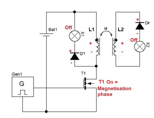
This schematic has two coils L1 and L2 in mutual connection and as can be noted the same phase polarity (dot). To understand what is happening in the coils, an analysis of the polarities is necessary.
As Melnichenko himself explains there are two phases to take into consideration, the 1st magnetization and the 2nd demagnetization.
1 When magnetizing, T1 closes and L1 becomes negative on the bottom and positive on the top with the same phase polarities on L2. D1 and D2 being in reverse polarity then X1 and X2 do not light up.


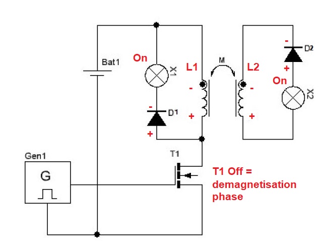
2 During demagnetization, T1 opens causing L1 and L2 to reverse polarity as shown in the following diagram:


Since D1 and D2 are now forward biased then both diodes conduct so that X1 and X2 turn on.

Practical experience will follow to demonstrate if this is indeed what is happening.

Jagau


Order By: Standard | Newest | Votes
Chris posted this 23 March 2022

Would be great to see more join in here!

What we share may sometimes be beyond some, but if others follow closely, it is obvious. V2 / 10,000 = Power, can you see a Gain here if you do the Math?

  • 5.182 / 10,000 = 0.00268
  • 27.182 / 10,000 = 0.07388
  • 0.07388 / 0.00268 = 27.5671


So, as Jagau has pointed out, the Magnetic Generation Index is: 27.5671. This may be ±5% Resistor error, but still, a very good result!

Achieved for a very simple, very cheap 20 minute experiment.

Best Wishes,

   Chris

  • Liked by
  • Augenblick
  • Jagau
Jagau posted this 23 March 2022

Hi all
Indeed Chris it is a very simple and useful circuit to build to keep for your future experience which comes from JL Naudin. I may have expressed myself badly by using the term power coefficient

I should have called it the magnetic generation index, exactly as N. Zaev called it and which was taken up by Jl Naudin as the magnetic power coefficient . I have attached Zaev's pdf to read more specifically about it.

It should be noted that this has nothing to do with the COP (coefficient of performance) which is completely different from the magnetic generation index to use Zaev's term.


Jagau

  • Liked by
  • Augenblick
Chris posted this 23 March 2022

Hey Jagau,

Fixed and updated as requested.

Best Wishes,

   Chris

  • Liked by
  • Augenblick
  • Jagau
scalarpotential posted this 25 March 2022

Hi Jagau,

Just thinking along:

It may be interesting to see scope-shots at DMM1 and DMM2, and also shots without the smoothing capacitors which hold DC voltage by storing charge, notice: Tdc=15%/2200=0.068ms, Tau=RC=0.22ms.

Also, the negative part of the demag ringing goes through the 'magnetizing' measurement and add charge to the cap before magnetizing. This can be seen without the caps.

Then, you can derive joules by looking at volt-seconds (P=V2/R, W=P*t, t=time that the voltage is there in phase with current).

Maybe I miss some fact. Not (yet) sure what Magnetic Generation Index really is.

cheers

  • Liked by
  • Augenblick
Chris posted this 25 March 2022

My Friends,

Energy in Joules = Power P x Time T, and Power P is the same as Watts W, Please do not confuse Time t in the Watts W Equation.

  • Power P = Voltage V x Current I x cos( Theta θ )
  • Watts W = Voltage V x Current I x cos( Theta θ )


If there is no Phase Angle, Theta θ, for example in a DC Situation, then Voltage V x Current I is sufficient.

Time is not factored into Watts W until you convert to Joules J.

More can be read on this Here.


Power is not hard, but it does take a little bit to learn, one has to force ones mind to Facts and avoid Guesses.

This is perhaps the worlds most simple experiment, Jagau has shared with you all, for those wanting to learn, its worth replicating.

Best Wishes,

   Chris

  • Liked by
  • Augenblick
  • Jagau
scalarpotential posted this 26 March 2022

Oops. W=Work in Joules, I used W as a symbol for Work, not as a unit Watt. Maybe using E was less confusing.

  • Liked by
  • Augenblick
Jagau posted this 29 March 2022

Hi all

This project is still being improved.
For the moment the power of the input is equivalent to that of the output and this even if we add two equivalent incandescent loads in addition to operating the circuit without any load.

In Andrey's theory, there is a way to give more than we receive, experiments continue in this direction, I will keep you informed of recent developments.

Magnetic generation index, as N. Zaev called it, is really a good tool to use for your project.


Jagau

  • Liked by
  • Augenblick
Selekolela posted this 30 March 2022

I have been doing my head in with this picture and had a flash, what if, (how do I put this into words), the primary coils are the loosely coupled ones on the outside, and the load coil is attached to the core, when the load induces a bemf into the core we swing the polarity of the primary coils and drive the magnetic field in reverse, at resonance, though the zero point and bounce it the other way as the same thing will happen in the negative region we reverse again and drive it the other way, in my head something wonderful will begin to happen,  

  • Liked by
  • Augenblick
  • Jagau
Jagau posted this 30 March 2022

Hi Selekolela
Welcome to the site,
Yes, that's the right way to make melnicehnko coils.
If you notice in my setup the 2 outer coils are a loose coupling on a 3.5 inch plastic tube, the third coil is on the iron sheet core as you ca see on my second experiment.


You have seen well, the magic is when one succeeds in obtaining more than what one gives, it is in the moment what I am trying to discover.

One thing is certain is that the excess energy is due to the fact that with a nonlinear or parametric resonance if you will, that is what is at stake here.
The following diagram helps us understand parametric resonance,  

just place the phases and keys in the right place. I've had success with this arrangement before in another thread, I'm just going to put it here.

Many who try to repeat Melnichenko's experiment make the mistake of thinking it's an ordinary transformer or even less a torus like JLNaudin experiment.

The principle of field separation field with an air core at a calculated distance from the nucleus makes all the difference in this experiment, do not try to carry out this experiment with good results if you do not apply these first two principles. When we short secondary side there is no reaction on primary which is not the case in an ordinary xfo

Many people have trouble understanding this last diagram on parametric resonance.
The 3 coils are not all in magnetic link but think more in terms of transmitter and receiver. What is important is the amplitude of the fields which is important here and not their magnetic addition. Thus a combination of air core and magnetic core (iron sheet) is important. We are talking about non-linearity in this case, in this kind of combination

Jagau

  • Liked by
  • Augenblick
Chris posted this 30 March 2022

My Friends,

@Selekolela, Welcome!

Its worth studding in detail: Andrei_Melnichenko_Inventions.

A simplification, and also seen in the GLED Videos, is the concept that the combination of L1 and L2 are twice the length of L3.


The shorter Coil becomes the trigger Coil, which must be triggered at Magnetic Resonance, which is the same as Antenna Resonance, but may be slightly different in Frequency because of the added Capacitive Coupling due to the Geometry.

In my thread: Chris's replication of Andrey Melnichenko's GLED shows the basic layout, and shows the required Asymmetrical Regauging seen many times.


The reason this machine is difficult to replicate, is due to Fitting the Coils to the Circuit, and not fitting the Circuit to the Coils. In other words, one winds the Coils, finds Magnetic Resonance and then builds the Circuit around the Known Coils Parameters, not the other way around due to too much guess work being required.

Electrical Energy is "Generated", this fact should always be in the front of every researchers mind first and foremost, E = -∂A / ∂t which is the Time Varying Magnetic A Vector Potential. This comes from E = v x B by default, via Faraday's law: ∮A.dl = Φ, and we have covered this already in all its genius, The Motionally Induced Electromagnetic Induction!


There is no doubt, Andrey Melnichenko, discovered what Tarriel Kapanadze also discovered. The only difference is Scale!

Best Wishes,

   Chris

  • Liked by
  • Augenblick
  • Jagau
Chris posted this 31 March 2022

@Jagau,

My Friend, for your information, and other interested readers, Itsu has replicated your work: Here

He has done a good job as usual!

There is more here my friends! Think in Dualities, or in terms of Asymmetry. Every time Current Changes: di/dt, we have a Source of Energy that can be used.

Best Wishes,

   Chris

  • Liked by
  • Augenblick
Chris posted this 31 March 2022

My Friends,

Itsu and Partzman have done some good analysis over on Itsu's Workbench. Worth a read!

Itsu made the statement:

So what about the FEMM simulation here: http://jnaudin.free.fr/2SGen/indexen.htm#simulation

In the video it says: "..the magnetic field outside the toroidal coil is null..."


And the Magnetic Field is, we have covered this here already, one place is the thread: Connecting the dots to Energy - The A-Field

The Magnetic A Vector Potential Varying in Time: E = -∂A / ∂t is the same as the Motionally Induced Electric Field, is the Source of Energy for Induction of the Secondary Coil. Here is an Image again:


If we recall Floyd Sweets statement on the very same topic:

Electromagnetic induction with no measurable magnetic field is not new. It is well known that in the space surrounding a properly wound toroidal coil there is no magnetic field. This is due to the superposition of the fields.

...

Ref: Floyd Sweet Nothing is Something


Walter Lewin also shows in his Long Solenoid Experiment, the Induction of a Voltage when there is no Magnetic Field:


I hope this gives you some answers as to why an E.M.F is "Generated" in this configuration, the Magnetic A Vector Potential is responsible for this remarkable feat, when there is no Magnetic Field.

Best Wishes,

   Chris

  • Liked by
  • Jagau
  • Augenblick
Jagau posted this 01 April 2022

Hi Chris


I rarely go to this site but I went to see. After verification, it only reproduces the part of JL Naudin's experiment on the tool that Naudin had created and share with all (generation index) in order to check if Naudin was using the correct method using the magnetization index tool .

He does not reproduce my experience on the Melnichenko effect, he just wants to know if Zaev and Naudin used the right method, he doubts their method. Zaev and Naudin used the right method I have no doubt that Naudin and Zaev were very competent people much more than me and them.

The experiment is very different from Melnichenko's, I don't use a toroid with a magnet as a pulsed transmitter, Melnichenko uses an air core as a pulsed transmitter without a magnet and there are other important differences that I will develop later. But it's still very interesting as you say to read about ways to create energy.

On this site there are too many people who have drastic responses and are very negative and disrespectful towards people like Tom Bearden it's a real shame, there is no control over bad influencers who think they know everything. I have no interest in returning to this site, I hate bickering I'm here on Aboveunity to talk about energy that's all.


Jagau

  • Liked by
  • Augenblick
Chris posted this 01 April 2022

Hey Jagau and all Readers,

I fully agree! For example, I just now read the last few comments, new ones since I last read, and saw this one:

Ref: Smudge's Comment


Now I have to say, the first line is just a Horrendously Absurd Comment to make:

It is nonsense to imagine that an air cored coil has a difference between magnetized field energy and demagnetized field energy.


I have a deep respect for Smudge, but I 100% Disagree with his statement!

I am going to focus on this statement, from what the OUR community may consider the most advanced member in the group, Smudge, is totally false and just a nonsense statement! We have experiments here at Aboveunity.com that prove this statement wrong every day of the week:

Ref: Chris's Non-Inductive Coil Experiment


Ref: Chris's Non-Inductive Coil Experiment


I have shown, a 10% Duty Cycle, on Time, and 90% Off Time, yet we get output through the entire 90% of the Off Time, when the Mosfet is Off, and actually sending Energy Back to the Input, already shown:

Ref: The Input Coil


Which as we all know, is Asymmetrical Regauging:

Ref: Asymmetrical Regauging


I am horrified and shocked that Smudge is so certain, in his mindset, that this Statement had to be made! This is the root cause of Dogma! We have undisputable proof that Smudges Statement is Naïve at best and False at minimum!


I just cant believe this sort of mindset still exists! Many here have seen the same as I have just shown! Many here have the same evidence I have just given, and this is the problem we face, in TOO Many peoples Mind, it cant be done, yet the proof shows, unequivocally, it can, its easy and cheap to reproduce!

Ask yourself: Is this Statement not the very Basis of Above Unity Machines at its Root? So to disbelieve, makes Above Unity Machines Impossible for the individual to reach the Goal, in the first place, does it not? Because one has already Ruled out the very means for Above Unity Machines! This mentality of: Something  for Nothing is a display of Ignorance, for Energy is still Conserved in Above Unity Machines, its simply the case, we have another Source of Energy we have introduced into the Machine that the very Actions of a Magnetising Current brings about in the first place! Importantly, this Magnetising Current does not need to be from the Primary Coil!

Historical Evidence shows: Floyd Sweet put 33 micro Watts in, and got 500 Watts out, so is this not evidence enough? In his later machines, Zero Input, 5KW Output, and the Statement made is now sounding sillier and sillier!

Smudges statement should read:

The difference between Input magnetizing field energy and Output magnetizing field energy is where Above Unity Machines fall within reach.


The fact of the matter is simply, Current I through Turns N, is a Magnetising Force, known as Ampere Turns NI. Ampere Turns NI, requires a specific Energy. This Energy is Mathematically defined by Ohms Law, as the Coil Impedance Z can be used as R, and the Voltage V, between the two Terminals, can be calculated: I = V / Z, or given we know the Current, P = I2 x R, either way, we only need two accurate values, to determine the others, for an accurate Energy Result.

That's why I have had to slowly bring information out, to help others see Truth!

In Time, this will become main stream and everyone will accept it as evidentiary, but that time is still a ways off yet!

Best Wishes,

   Chris
  • Liked by
  • Jagau
  • Augenblick
Jagau posted this 01 April 2022

To tell you seriously, I had the same conception as him a while ago.
When I started to evolve and read successful inventors like John Bedini and Floys Sweet that's when everything changed.
I had the chance to work a large part of my life in a field that I adore, that of electronics, and there were phenomena that I observed but that I could not explain at that time. Today with a certain hindsight and a lot of experimentation I found that it was possible to go beyond unity as you know we have experiments carried out here on this site which confirm it but are not published for the moment it will come.

As Chris has told you before and I tell you too don't let others think for you and influence you in your experiments. Try and go for it, aboverunity already exists, you just have to use it.


Jagau

  • Liked by
  • Augenblick
  • Mimo
Jagau posted this 03 April 2022

Hi all

Update
When JLNaudin built his demagnetization index tool, he took into account very important parameters such as

the impedance path ( Z )


As I operate in the same frequencies and coils inductance, I did not have to modify the circuit he designed. If you change the frequency and the coil you will have to do some calculations on the impedance of your circuit.

Jagau

  • Liked by
  • Augenblick
Chris posted this 04 April 2022

My Friends,

The debate on Measurements has begun over at our.com. The method that some are recommending, I do not agree with!

@Itsu, I believe, if you do the Integral( A x B ) on a straight DC Load, and see what answer you get, you will be surprised at the answer!

Current is Current, and Voltage is Voltage, and over Time, the Energy Product will be Correct only one way and not by adding Math into the equation that is not part of the overall Energy Product Equation!

Electrical Energy is defined as: V x I x Cos( θ ) = Wats W, and Energy is defined as: V x I x Cos( θ ) x t = Joules J.

There is no Integral defined there, although the Modern Oscilloscope should do a full integral over the Scope Buffer anyway, which will be: Instantaneous V x I through the Scope Buffer. If the Scope Buffer has 10 Million Points, then this is V x I + V x I + V x I... 10 Million times. Which is the same as Integral( V x I ) but not Instantaneously.

All I see is people trying to overly confuse what would other wise be a simple, already very well defined procedure which every Modern Oscilloscope can handle by default.

Best Wishes,

   Chris

  • Liked by
  • Augenblick
Chris posted this 08 April 2022

My Friends,

I just want to note, on initial perusal, I agree with the measurements Itsu has done here.

  • Magnetisation Phase: 0.259uJ
  • Demagnetisation Phase: 9.943uJ
  • Magnetic Generation Index is: 9.943uJ / 0.259uJ = 38.39


However, one or two things I could point out. Like White trace is slightly off screen, and time base could be set better, and the waveforms look odd for this experiment. However, Itsu has done a good job, from the data Itsu has supplied, accurate enough to make a determination, to warrant further exploration.

Apparent Power is VA and is when a Phase Angles Exists! Small Phase angles are there, maybe 10 Degrees, or less, but the scope will account for this in its Math. The use of Apparent is non-sensical! It is apparent that some do not wish to learn simple things, is a statement that comes to mind!

I was not understanding the original post, about the Integral, above, and no mention of Cursors was mentioned for Scope Waveform Selection.

It is worth noting, again, I believe Itsu has done a good replication of the effect Jagau is working on showing you, but the approach I believe is different, if you re-read Jagau's first post. It is nice to see some are paying attention to important effects!

@Jagau, sorry for the distractions here, I will stop posting now and let you continue. 😉

Best Wishes,

   Chris

  • Liked by
  • Jagau
  • Augenblick
Jagau posted this 11 April 2022

That's very good Chris
The advantage here in this site, is that one can emit ideas and discuss them without bickering. I appreciate all comments.

An update is coming with new results.

Jagau

  • Liked by
  • Augenblick
Jagau posted this 15 April 2022

The Melnichenko coils use reactive energy to light the first lamp and since the core of the system is not magnetically linked by a ferric conductor but rather by a flux link the second lamp also lights only with the supplied flux. by the fields shared by the system.

The magnetic flux is at 90 degrees to the induced current in the coil.

It is this second lamp which is the free energy.

The first lamp consumes all the energy that will be lost and wasted and is equal to the input consumption of the system. the consumption does not change even if the two incandescent lamps are closed. The second lamp is currently weaker than the first but it is free energy. These are two incandescent lamps of 115 volts AC and 4 Watts each lamp of power. The second coil in the center of wider one is completely removable as Anrdey quote.

I used IGBT switching type with TL494 oscillator with DTC and Frequency adjustable. Frequency is about 1.1 khz and 43% DTC

Jagau

  • Liked by
  • Augenblick
  • Mimo
Jagau posted this 17 April 2022

After doing some experimentation with the Melnichenko effect, I would simply describe it as automatic cascading amplification.

That is to say, we pulse a first air coil (wider one) which also produces an external field on two other coils (removable coils) whose center has a ferromagnetic core and during demagnetization the reactive energy which has been recovered by the set of diodes on the air coil core and added to the energy recovered during demagnetization is amplified in cascade by the 3 coils during demagnetization.

In fact we pulse 1 coil and we harvest on 3 coils. It is the only way to get free energy. You have an example described above.

Jagau

  • Liked by
  • Augenblick
  • Mimo
Chris posted this 19 April 2022

Hey Jagau and all Readers,

It would be great if more would join in and share! It would be great to see more replications of this very simple and cheap to replicate effect!

Problem is, so many are either Lazy, or too busy with life!

This effect has been verified by myself and Itsu Here. It is NOT a spurious Effect, it is verifiable and simple to observe. We have been showing you this for quite some time now! It is the path that leads to Free Energy Systems, once understood properly!

I am very pleased, the website is much more stable now, much faster and much much more pleasurable to visit and use! So please share your experiments as we do with you!

Other forums, they have very little to nothing to share! They are lost! We have the Technology and have shared all of it with you, all you need do is learn it and make steps to progress. We will help!

Why do I say this, well, History has shown many machines, none of them have been understood, and or replicated:


No one was successful, many tried! The quote: Little Steps for Little Feet - Sir Richard Feynman, is true!

Best Wishes,

   Chris

  • Liked by
  • Jagau
  • Augenblick
hermesatar posted this 20 April 2022

Jagau,

Your setup with one aircoil and two ferromagnetic core resamble one version of the Hubbard Coil.

I have always consider that there could be an outer air coil that is loosly coupled to the 9 inner ferromagnetics coils.

I have 9 long ferrite cores so I only have to wind them with copperwire and then wind an outer coppercoil over the 8 ferrite cores.

The reason why I haven't done it before is because I have always seen the conversation of energy in the hubbard coil.

But seeing the outer air coil as an transmitter coil and the 9 ferrite cores as reciever coils changes my line of thinking.

Only test will show if there is an energy gain or conversation of energy. I link to my hubbard coil page:

http://gratisenergi.se/hubbard.htm

Best Wishes, Hermes

P. S Jaugau, thank you very much for your explanations of this interesting topic and Chris I too are very satisfied with the speed of this very important website.

Chris posted this 20 April 2022

Hello Hermes,

Pleased the speed is much better! Thank You for letting me know!

Your Statement:

But seeing the outer air coil as an transmitter coil and the 9 ferrite cores as reciever coils changes my line of thinking.


This is right, but there is more! Each and every Current changing in time can be a Transmitter and a Conductor of the same length or a multiple of, is the Receiver. This is true of any Coil Arrangement. of arrangement of Conductors.

Antenna Theory, especially the concepts of Wave Mechanics is the exact same analogy:


The concepts covered in the above videos are the same, especially with the Superposition Concepts: @ 1 : 50 of the second video.

Best Wishes,

   Chris

  • Liked by
  • Jagau
  • Augenblick
Jagau posted this 20 April 2022

Hello Hermesatar

Welcome to AU.com
Your website is very interesting thank you for sharing it.


I don't know the Hubbard coil very well, but I will take the time to study it because it interests me a lot.
At first sight it seems that there is a lot of similarity between the two projects.

thank you for letting me know and as I do not know Hubbart very well,  I will come back to you with my observations in another post.


Jagau

  • Liked by
  • Augenblick
Jagau posted this 20 April 2022

Hi Hermesatar

I looked at Hubbard's patent and as you say there is a lot of similarity to Melnichenko's.
The principle of field separation is present and also the external coil which will transmit others connected to a core in the case of Hubbard several core.

The big difference is that it probably uses round iron screens to delay the max and minus current phases.
They should in principle be very thin or even like thin pin hole screens. The hardest part is adjusting the phases, that's what I'm working on right now.


Jagau

  • Liked by
  • Augenblick
Jagau posted this 21 April 2022

For those who want to build I use this concept

3 coils,

coils  number 1 is transmitter and two other coils are receiver

Jagau

  • Liked by
  • Augenblick
  • Mimo
Brian posted this 23 April 2022

Hey Jagau

I have started with the replication, but the first challenge was to find a suitable core for the POC coils. I did not have a transformer core of suitable size so tried an out there idea I had read some time ago using a bundle welding blast rods I had left over. These are basically carbon rods coated in copper. Initial results are not promising. I have also thought of using a bundle of iron 4" nails. But I think I need to go to the dump and find a old transformer of reasonable size. Is this what you have used for the core?

Are you able to supply the details of your primary and POC coils diameter, turns and wire length?

Thank you for sharing your work.

Kind regards

Brian


  • Liked by
  • Jagau
  • Augenblick
Jagau posted this 24 April 2022

Hi Brian


If you study this video well, everything is written at the bottom of the schematic. Print it

The suggested numbers of turns for N1 and N2

The frequency if you used a transformer core or ferrites core

The powers, the voltage of tubes,  everything is there

Have a good experiment

jagau

  • Liked by
  • Augenblick
Jagau posted this 25 April 2022

Hi all

I made a test of new HTML editor

During the construction there are important parameters to calculate this depending on your construction and how you made it.
To help you, I have placed the main calculation formula and the definition of each of the items in the image below. You will thus be able according to your needs to calculate your output voltage for a coupled inductor with very low coupling coefficient (K)

 ok chris it works very well for me thank you for everything

Jagau

scalarpotential posted this 26 April 2022

The formula of the stored energy in a coil is based on conservation of energy, not on the actual energy of/in the field. Its energy is equal to 0.5*LI^2 a function of current integrated over time. Which variables must be manipulated to get demagnetizing energy > magnetizing energy?


  • Liked by
  • Jagau
  • Augenblick
Jagau posted this 26 April 2022

The Melnichenko effect is based on the fields séparation and of total accumulated energy amplitude of the fields wth its effect squared.

The formula given above is for those who want to build with very specific starting parameters and voltage you want to reach.

It would be too simplistic to only use what one can have as stored energy without knowing how to make it.


Jagau

  • Liked by
  • Augenblick
baerndorfer posted this 26 April 2022

what i've learned so far...

when i switch a coil with a mosfet, then i get this sharp pulse with a damped oscillation behind the trailing edge. the frequency of this ringing is coming from the core-material. so the material is answering my knocking.

now when i switch this coil with this frequency or a harmonic one, the material is ringing/shaking.

every coil that is part of this core will get an extra amount of energy which is caused by that shaking.

i don't know if it is acoustic resonance or magnetic resonance. it cannot be magnetic nuclear resonance...

still trying to build an analog circuit that can manage this.

regards!

  • Liked by
  • Jagau
  • Augenblick
raivope posted this 26 April 2022

Hi Jagau,

Tested my Melnichenko setup where primary was 30m wire 1.4mm on a 110mm sewer pipe. It makes about 80 turns. There was a secondary as well but it is not important right now, it did not affect the process.

What I was afraid of that and what happened was that I cannot run the power supply above 4V or the primary's CEMF (collapsing EMF) voltage goes over 100V that is the MOSFET voltage rating. Mosfet starts to clip it. Of course I had the UF4007 (fast) diode and load in a CEMF cycle as well, but it was not fast enought to catch the primary's reversed voltage.

I guess it is wise to use a SCR (Thyristor) instead of MOSFET, because SCR shuts down automatically when current ceases, but this becomes more complex, because then I have to use single rectified AC period input power instead of DC supply and trigger the SCR at the right moment. Heh, it looked easy, but... back to the drawing board.

There is also an option to reduce MOSFET turn off speed, protect it from the peak with a small capacitor.

Best,

Raivo

  • Liked by
  • Jagau
  • Augenblick
scalarpotential posted this 26 April 2022

what i've learned so far...

when i switch a coil with a mosfet, then i get this sharp pulse with a damped oscillation behind the trailing edge. the frequency of this ringing is coming from the core-material. so the material is answering my knocking.

now when i switch this coil with this frequency or a harmonic one, the material is ringing/shaking.

every coil that is part of this core will get an extra amount of energy which is caused by that shaking.

i don't know if it is acoustic resonance or magnetic resonance. it cannot be magnetic nuclear resonance...

still trying to build an analog circuit that can manage this.

regards!

I think it's a mechanical vibration in the audible acoustic range.


https://www.researchgate.net/publication/322482698_Acoustic_noise_characteristics_of_inductor_according_to_magnetic_powder_core_building_structure_for_inverter_application

Jagau posted this 26 April 2022

Hi Raivope and baerndorfer

The best way to pulse this type of circuit is to use an IGBT
At low frequencies they are easier to configure, moreover, it is their strong point and, moreover, it is the method that Andrey Melnichenko uses in high side mode.


With this large reactive power produced by the primary, if you use a mosfet the gate must be very well isolated by a 10k, and the reactive power must be picked up in a load, otherwise your MOSFET failed. An SCR is too slow for this type of circuit. So IGBT is the right way.

The core is only used for the secondary in this configuration.

This is where we get the power greater than 1

Tell me what pulse circuit did you use?


Jagau

  • Liked by
  • Augenblick
  • Mimo
raivope posted this 26 April 2022

There is no big difference between IGBT and MOSFET to my knowledge. IGBT is slower, it has a mosfet-on-transistor inside. Some IGBT-s do not have inner diodes.

I used quite advanced circuit - using galvanic isolated ultfafast comm IL610 mediated signal that uses mosfet driver about 30ohm impedance to gate for floating pulses. Pulsed the coil from the positive rail. I could have had SiC diode on CEMF line for better collection speed.

Because the primary has an aircore, it tends to have very high peak response. I can lower the speed by buffer capacitor in parallel to mosfet-switch, perhaps 100n 400V.

[Edit] Will try out also mini capacitor in parallel to diode and coil. So many ways todo it.

Raivo

  • Liked by
  • Jagau
  • Augenblick
Jagau posted this 26 April 2022

 Hi Raivope

In this project I try as faithfully as possible to reproduce Melnichenko's experiment.
Melnichenko used an IGBT because even if the frequency which is slower than a MOSFET but here we used it at very low frequency between 400 hertz and 1.1 khz for this project, the IGBT is very easy to configure in high side mode (very important), it is very well insulated against ESD (eloctrostatic discharge) a significant advantage and therefore it is not disturbed when overvoltages and strong currents occur, which is not the case with a Mosfet.

So I think it's the right choice as the inventor uses it, but it's your choice if it works well for you. That's the beauty of trying and experimenting. Yes as you said many possibility others wayto do it.  Inventors never say everything, even in their patents they give that the principle in general is up to us to seek and find.

 As you are interested I will tell you a little more, in his video he does not say everything, as an example it is not the right way to recover reactive energy, you must have two separate ground to succeed in this project. One for power supply and one for reactive energy recovery.

Jagau

  • Liked by
  • Augenblick
  • getreal156
Chris posted this 01 May 2022

My Friends,

@Itsu, I believe you should keep working on this subject, if you wish. You will see greater benefit if you keep going!

@All Other Readers, this is a simple experiment, that shows something that no other Forum has ever been able to show! Jagau has given you great advances!

There is always more, so stay tuned, to the only Forum in the world that has answers!

Best Wishes,

   Chris

  • Liked by
  • Jagau
  • Augenblick
Jagau posted this 01 May 2022

How is the energy transported related to the amplitude?
As the amount of energy carried by a wave is related to its amplitude. The amplitude of a wave therefore refers to the maximum amount of + and – displacement and the energy that is transmitted to a pulse will only affect the amplitude of that pulse. It will not change any parameter other than the amplitude.


You have a way here to create more energy than you give out.

At Aboveunity.com you have a way to do it and we want it to be shared.

<IMAGE LOOK AT BACKUPS>

Jagau


  • Liked by
  • Augenblick
Jagau posted this 02 May 2022

Work on the Melnichenko effect is progressing slowly but surely. The latest tests show that the effect can be increased by delaying or adjusting the phases of the currents between the input and the output.
As Tesla explained with its patent 433702 this is possible.

Eexperiments are currently in progress,
Jagau

  • Liked by
  • Augenblick
  • Mimo
baerndorfer posted this 02 May 2022

hi jagau,

can you point out where the tesla patent describes the effect from melnichenko?

i studied this thing couple of times but canot find a link to andrej.

do you think, that shielding a coil with a magnetic circuit has the same effect as we can see on the 2 e-cores?

have a nice day!

  • Liked by
  • Jagau
  • Augenblick
Jagau posted this 02 May 2022

Hi Baerndorfer

Yes I think that is what is not said in Melnichenko's video. The shield when it reaches a certain saturation, allows the voltage to pass quickly and corrects the phases of the primary and secondary current.
Tesla describes it very well in 433702 :


t he lag of the primary behind the impressed electro-motive force may be diminished by loading the secondary with a non inductive or dead resistance-such as incandescent lamps-whereby the time interval be tween the maximum or the periods of the primary and secondary currents is increased.


I realized that an incandescent lamp which is a dead resistance and thus increases or decreases the effect so a shield does the same thing.

My experiences are not finished on this point but it looks very good.


Jagau

Jagau posted this 02 May 2022

By calculating the correct secondary capacitor value, the light is more intensively

bright without any change in power consumption at the input.
It was enough just to adjust the power correction factor PF and it works.
 

Jagau

  • Liked by
  • Augenblick
  • Mimo
Jagau posted this 02 May 2022

The effect is really interesting! I can definitely say
that to avoid negative factors and limitations, you should move away from using a ferromagnetic core on the primary,

i.e. use air coils on the primary and ferromagnetic on the secondary.
The Melnichenko effect is truly an aboveunity system. You will see it in the next video
Jagau

  • Liked by
  • Augenblick
  • Mimo
Jagau posted this 02 May 2022

My experiments on this phenomenon are at the beginning and I believe to have good results.   Is it possible to make Lenz Law non-existing, I believe melnicehnko solved some of this problem by making a nonlinear transformer this way:

The primary is air core and the secondary is ferromagnetic, nothing new yet but with an air gap between the two the output does not affect the input.

I would explain the Melnichenko effect this way: Lenz's law is almost non-existent or negligible because we use this type of non-linear transformer arrangement as there is no load connected to the secondary (idle).
The load is only connected in the demagnetization phase to the secondary.   
Read this you will understand what I mean in the principle of Melnichenko
https://www.physicsclassroom.com/class/waves/Lesson-2/Energy-Transport-and-the-Amplitude-of-a-Wave

For other questions about Lenz's law, I invite you to follow this demo by Professor Walter Levine from MIT, you will have your answers well explained

 Jagau

  • Liked by
  • Augenblick
  • Mimo
baerndorfer posted this 02 May 2022

what i can add is, that this works also without an air-gap. but then you will need POC-coils for the 'magic' to happen. like wistiti did in his thread.

regards!

  • Liked by
  • Jagau
  • Augenblick
Jagau posted this 02 May 2022

It is the principle of the separation of the magnetic fields which is a basic condition in the Melnichenko effect, if there is not this condition, it does not work, I have checked it. There is no POC in this configuration.

There are different ways to achieve aboverunity, each principle is different.

If you have different evidence show it,  but surely not the Melnichenko effect. 

If someone has done something similar to Melnichenko effect show it to me.

The subject of my thread is important and requires a lot of time and experimentation, we have to stay on the main subject.

Jagau

  • Liked by
  • Augenblick
  • Mimo
baerndorfer posted this 02 May 2022

yes melnichenko uses 2 e-cores seperated by air-gap and showed, that there is more energy in the whole system. this is fact.

but when you know what he did and when you know what POC can do. why not combining both ideas?

have a great day!

i do not want do destroy your thread - peace!

Jagau posted this 02 May 2022

In order to properly situate us in the thread I made a short summary and for those who want to build.
When he started his research, Melnicenko had this type of arrangements like this:

At that time he used 2 ferrite E core with a well calculated air gap, where he placed a dielectric material. You have in this image all the useful information for the construction.

The performance of his device as youca see at this time was, for an input of 140 watts he obtained 235 watts of total power output. Which gives us a yield of about 1.7


He then builds a new arrangement with a large air core like this:


and one or two coils inside this large air coil.

It is with this arrangement that I am experimenting at the moment and

the performance results compared to that of Melnichenko are about the same.

For an input of 4.5 watts I get 7 watts at output, this is the best performance so far that I have managed to get since I built devices like this.
1.56 is an excellent result to date.

So I confirm that melnicehnko's device is really abovetunity machine.


Jagau

Topic Is Locked

We're Light Years Ahead!
Members Online:

No one online at the moment


What is a Scalar:

In physics, scalars are physical quantities that are unaffected by changes to a vector space basis. Scalars are often accompanied by units of measurement, as in "10 cm". Examples of scalar quantities are mass, distance, charge, volume, time, speed, and the magnitude of physical vectors in general.

You need to forget the Non-Sense that some spout with out knowing the actual Definition of the word Scalar! Some people talk absolute Bull Sh*t!

The pressure P in the formula P = pgh, pgh is a scalar that tells you the amount of this squashing force per unit area in a fluid.

A Scalar, having both direction and magnitude, can be anything! The Magnetic Field, a Charge moving, yet some Numb Nuts think it means Magic Science!

Message from God:

Hello my children. This is Yahweh, the one true Lord. You have found creation's secret. Now share it peacefully with the world.

Ref: Message from God written inside the Human Genome

God be in my head, and in my thinking.

God be in my eyes, and in my looking.

God be in my mouth, and in my speaking.

Oh, God be in my heart, and in my understanding.

Your Support:

More than anything else, your contributions to this forum are most important! We are trying to actively get all visitors involved, but we do only have a few main contributors, which are very much appreciated! If you would like to see more pages with more detailed experiments and answers, perhaps a contribution of another type maybe possible:

PayPal De-Platformed me!

They REFUSE to tell me why!

We now use Wise!

Donate
Use E-Mail: Chris at aboveunity.com

The content I am sharing is not only unique, but is changing the world as we know it! Please Support Us!

Thank You So Much!

Weeks High Earners:
The great Nikola Tesla:

Ere many generations pass, our machinery will be driven by a power obtainable at any point of the universe. This idea is not novel. Men have been led to it long ago by instinct or reason. It has been expressed in many ways, and in many places, in the history of old and new. We find it in the delightful myth of Antheus, who drives power from the earth; we find it among the subtle speculations of one of your splendid mathematicians, and in many hints and statements of thinkers of the present time. Throughout space there is energy. Is this energy static or kinetic? If static, our hopes are in vain; if kinetic - and this we know it is for certain - then it is a mere question of time when men will succeed in attaching their machinery to the very wheelwork of nature.

Experiments With Alternate Currents Of High Potential And High Frequency (February 1892).

Close