Modified Armstrong Oscillator por Jorge Lezana

  • 2.5K Views
  • Last Post 11 February 2020
Jlezana posted this 22 October 2019

Good Friends, Well for some years now, I have been observing and trying to replicate some projects about FreeEnergy, to try to understand and try to separate the real from fiction, the big problem, is that not everyone gives much information about the origin of their works, so it is difficult to go to the source of everything and be more accurate in the conclusions when one tries to replicate.

After working with power transmission replicas by 1 driver, which you can see on my channel the youtube

Video 1: /watch?v=6Z_q6LkmPis

Video 2: /watch?v=4XnVySuFJRo

Video 3: /watch?v=nw6my2X-57g

Video 4: /watch?v=PEHHTpIuBD4

Video 5: /watch?v=W1dnpBsptCg

If time permits, I will try to make some thread about this.

I began to study how to make an economic oscillator that would allow me to replicate these experiments, but without expensive instruments, it was there that I reached a couple of schemes that worked for me. But I didn't know where they came from, until recently.

It was there that I arrived at several sites and schemes that worked for different purposes, one of them was that of Akula, and that of Lasersaber, both used a transformer that eventually worked in resonance, worked with both schemes, worked, but when the power was disconnected , the LEDs went out in less than 1 second. For its simplicity, I spent working with the Lasersaber scheme, and arrived at the source of the scheme, and coincidentally with some modifications, it also worked for my power transmitter for 1 conductor.

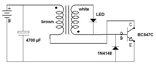
The original Oscillator is called the Armstrong Oscillator (it may come even further behind than Tesla itself, but I don't know), and it is a small oscillator that oscillates by Magnetic coupling between its coils, the Original scheme is this:

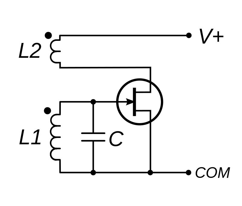
Where C, can be removed, if the coil has enough capacity between turns, to put it to work, here the Used Transistor is very important, it does not work with anyone.

If we observe the scheme of lasersaber SJR Looper V4.1:

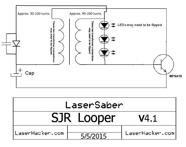
We see its similarity, with the Original scheme.

That also has something of the Joule Thief circuit, the big problem of the Joule Thief, is that it can work with little voltage, at the cost of a high current, and here the current is the great limitation to achieve autonomy without connection of the source of feeding.

Returning to the LaserSaber scheme, the transformer was not so simple to make, nor to tune, here we cannot adjust the frequency with an external capacitor or regulate the pulse frequency. So adjusting it becomes very difficult. It does not always work, and when I did it in my case, it consumed so much current, that it did not stay on after removing the power.

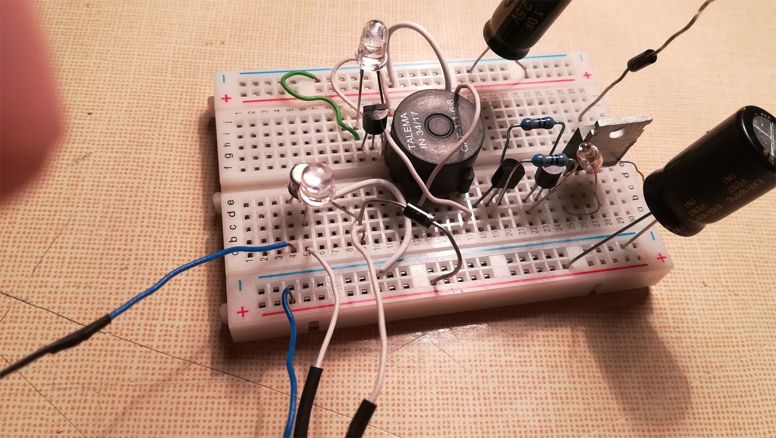
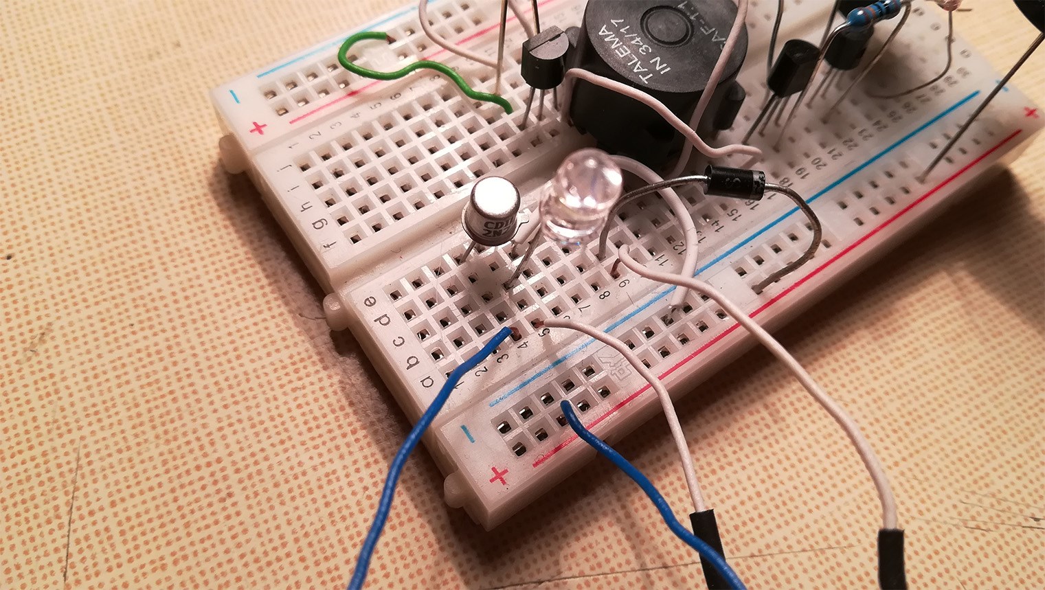
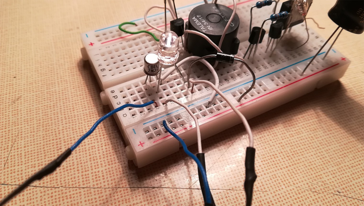
I spend a lot of time until it manages to operate the circuit fairly well, with almost any ferrite transformer that we can catch on any unused PC power supply.

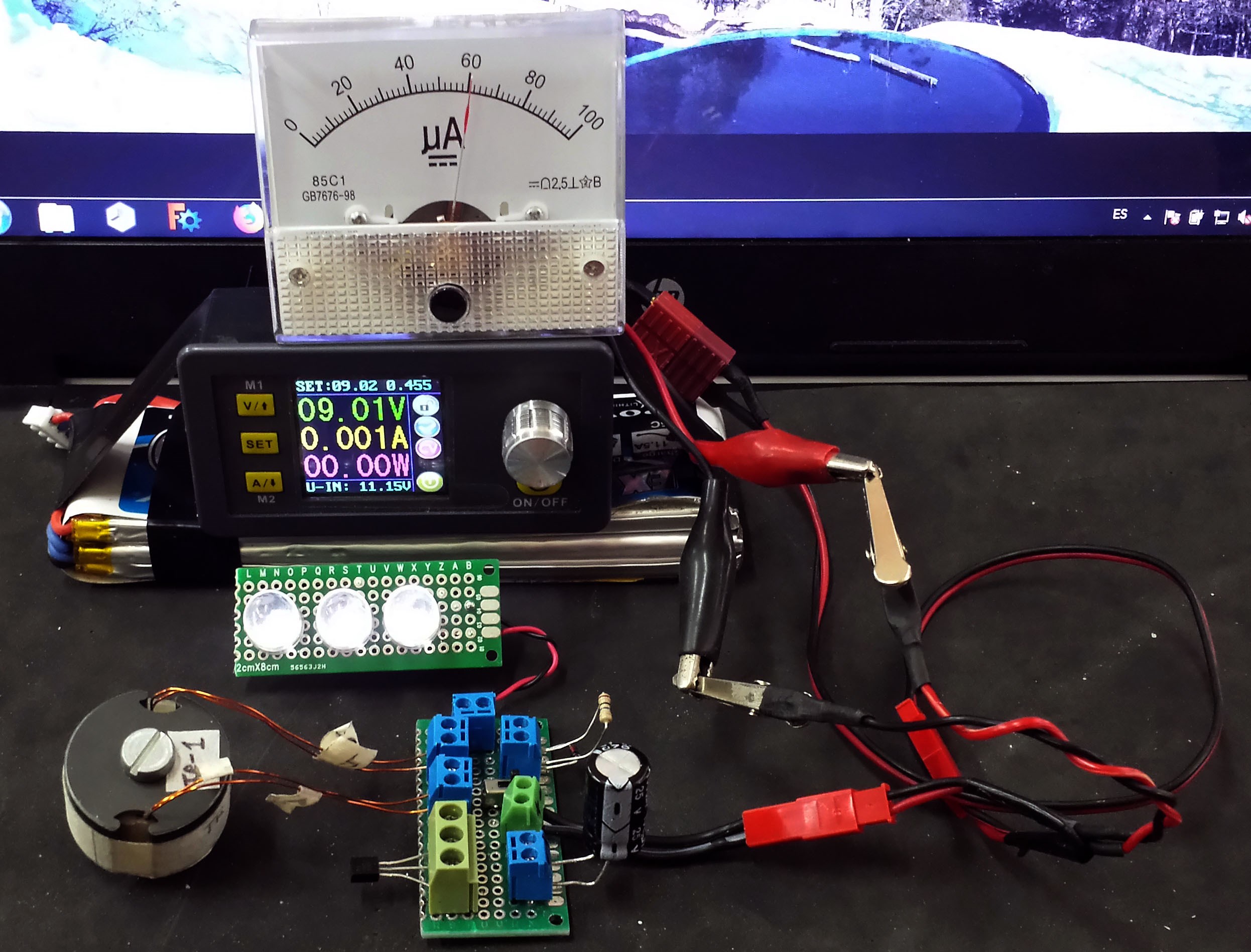
And as you can see it works:

 And the Video in a Test:

VIDEO: 


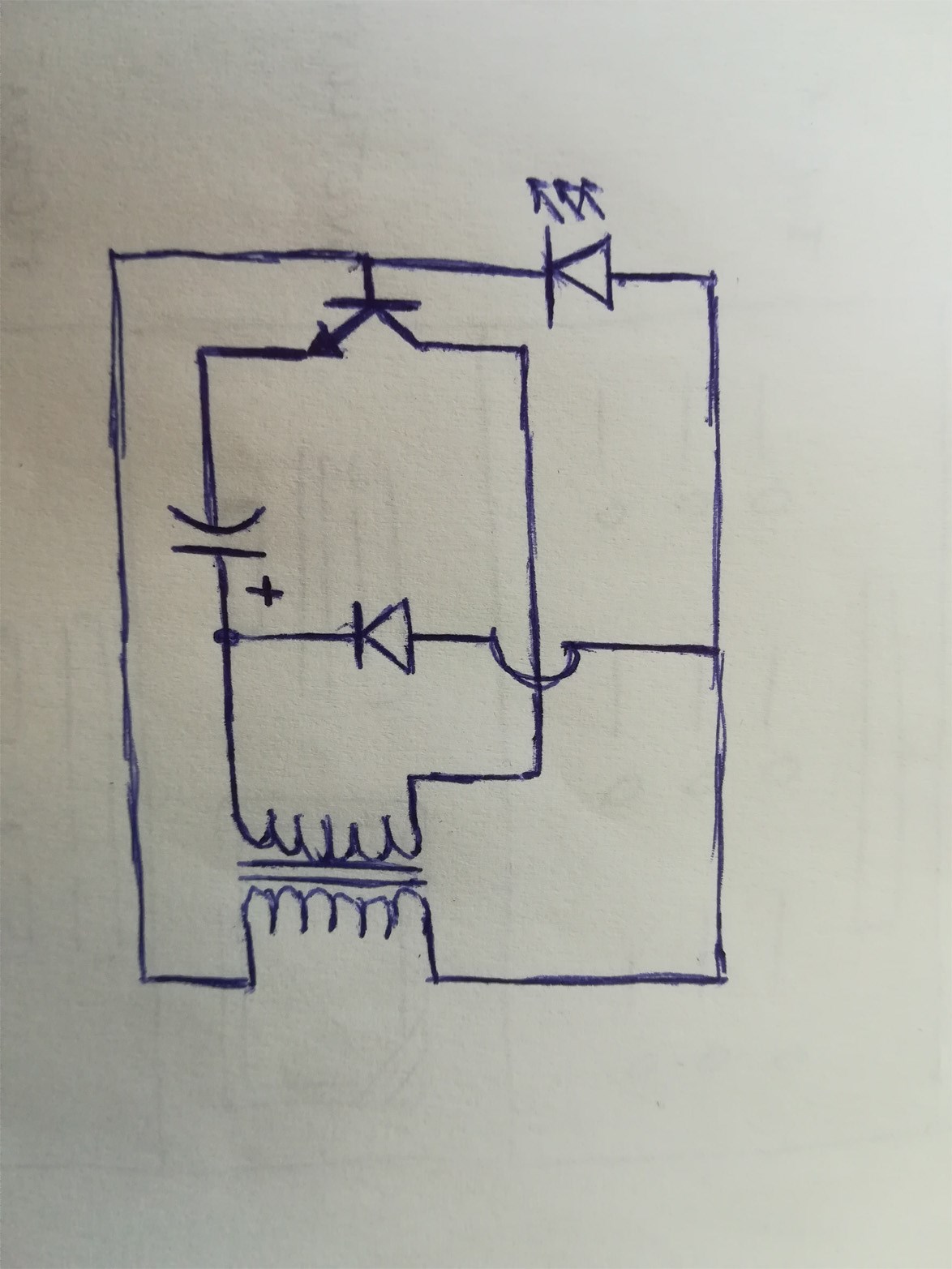
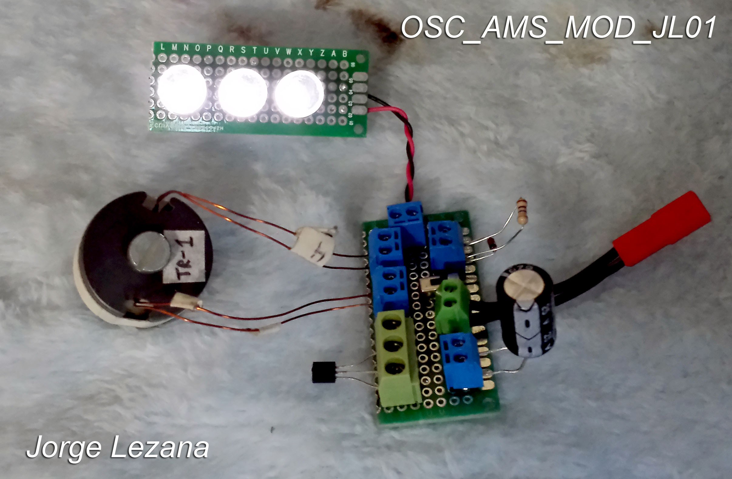
The final scheme I work with is as follows:

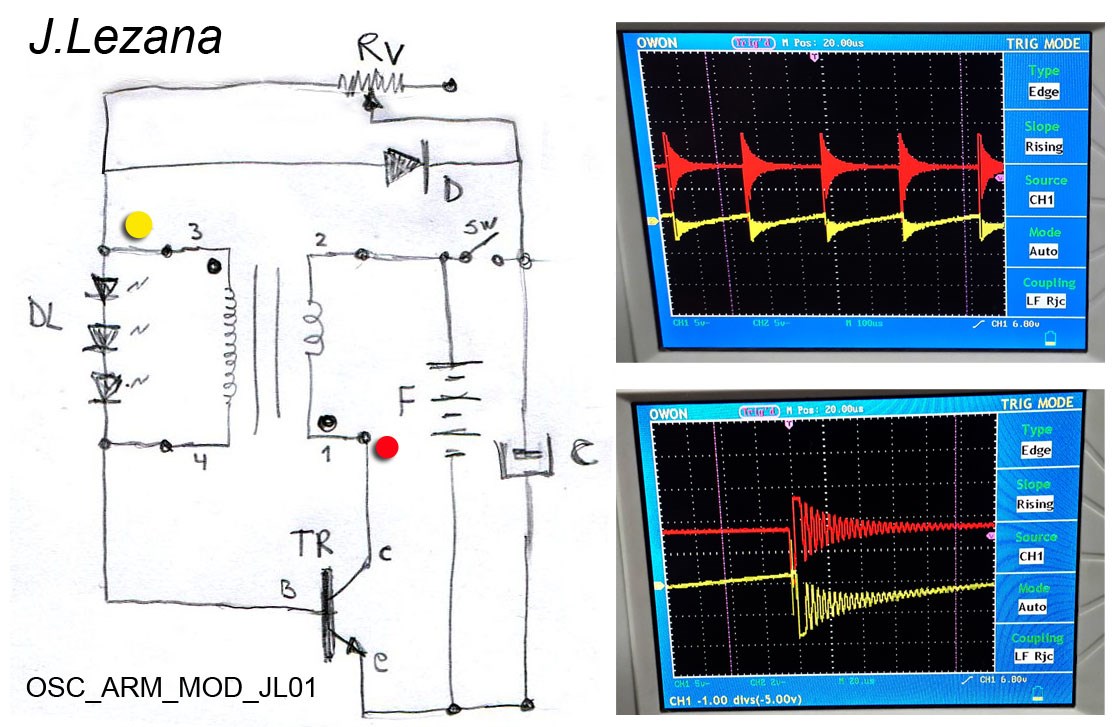
In it you can see a red and yellow point, where you can see the waveform at these points.
The detail of the elements is:

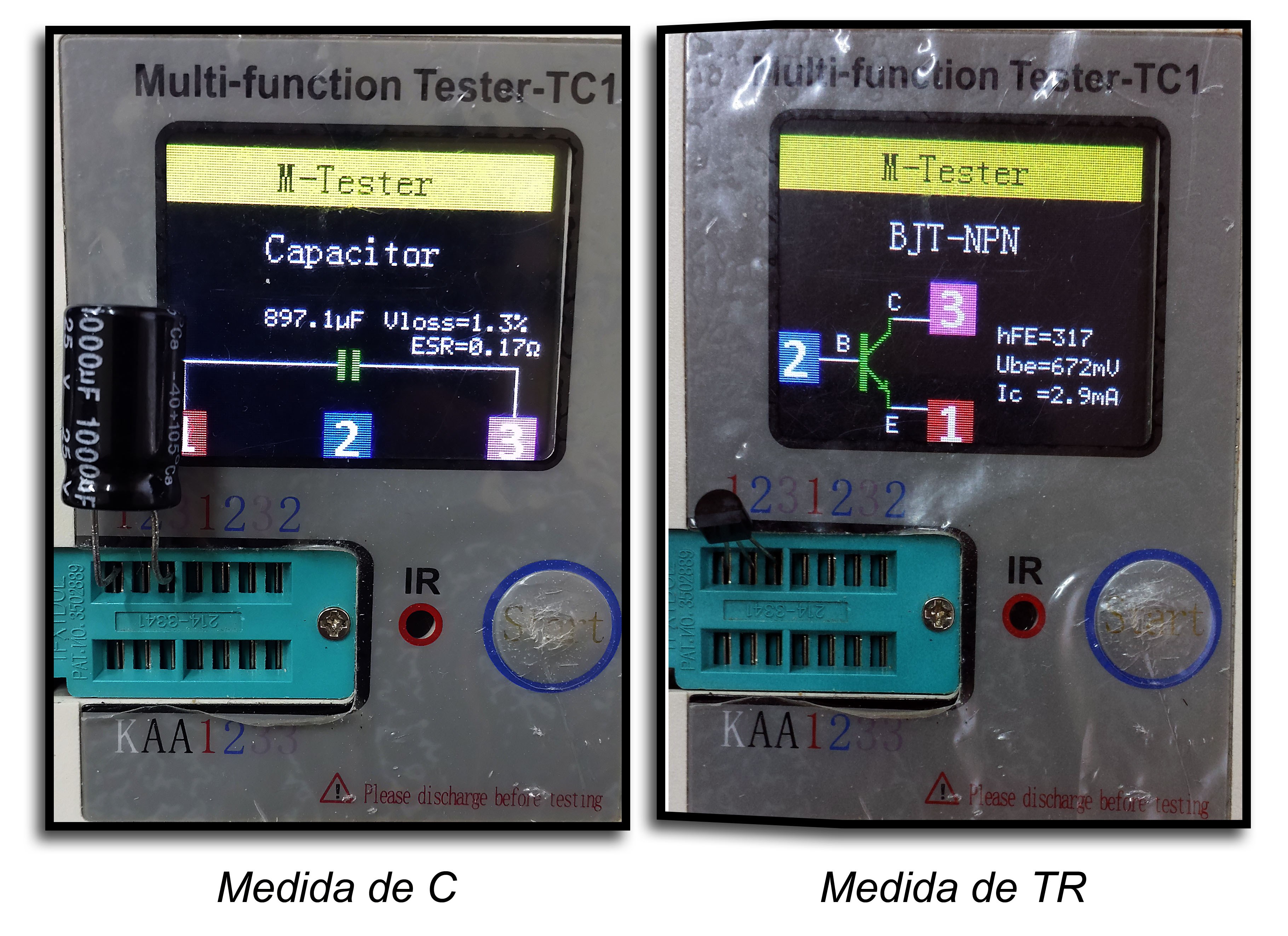
-TR: NPN 2n3904 Transistor I recommend buying several, and choosing the one with the highest HFE, over 300 ideal.
-C: 1000uF x 25V Electrolytic capacitor.
-D: Fast diode 1N4148
-DL: High Brightness Diodes between 2.8 and 3 Volt for a Working current of 10mA.
-RV: Variable Resistance between 1 - 30 Mega Ohm

This Resistance is important and must be found for each transformer that they make, it will allow to adjust the Working Current of the entire Circuit that Round between 50 and 120 uA and also make the LEDs turn on.

The transformer I use, they have a 1: 3 Turning Ratio I've used from thin and thick wire, they all work for me,

The one in the photo and video is about 20 laps in the Primary and about 50 in the Secondary, of the same wire gauge. (1 meter of wire in the primary and almost 3 meters in the secondary)

The muffled frequency in my circuit is approximately 300 KHZ and the Pulse is around 4.5KHz.

An important detail to expose here, is that the Fast Diode 1N4148, is not necessary at all, can work without it. In Tests I did I realized that at high voltages, there is no BFEM that can help maintain the charge on the capacitor, depending on the transistor, the BFEM appears at voltages below 4 Volts. I could verify this, with the Switch that I put between the source and the Condenser.

The idea of charging the capacitor at about 9 Volt. is to allow it to discharge slowly and reach the working limit voltage of about 2 Volt. If they load it with 3 Volt, it won't last long.

The current consumption of my Circuit is only 60 uA. At 9 Volt, with a 1000uF capacitor it gives me a time on of about 2 Minutes. While the LEDs look slightly on for much longer, the useful light I think is around 2 minutes.

At this point I have to make it clear that the LEDs are not at maximum brightness. The idea is to get the maximum brightness with the least amount of current in the input.

I encourage you to try this circuit and show your results.

In order for us to move forward, it is important to place your test data:

Power On Time:
Capacitor Charge Voltage:
Work Current:

I will keep an eye on any comments, and I hope that my translation from Spanish to English is understandable.


Greetings from distant lands ..
Jorge Lezana
Valdivia-Chile

Order By: Standard | Newest | Votes
Mitza84 posted this 22 October 2019

HI Jorge is nice that you get this consumption il replicate yours also, i play with this schematic and my amp draw is between 1-10mA  and with 10mA you get realy good light like real flashlight.  Good job and thank you for the good work . 

Mitza

Jlezana posted this 22 October 2019

Hello Mitza84 Thank you for your comment ..

In my scheme, the consumption is manipulated with the RV, adjusting to a lower value, you will be able to increase the consumption in exchange for more brightness, to the point of even lighting much more than the LED illuminates to 3V. you have to be careful not to burn the led ..

I leave some captures of the measurements of the capacitor and transistor and in addition to the consumption in full operation.


Regards

J.Lezana

Deny posted this 23 October 2019

Hello everyone in the past I replicated lasersabers's sjr looper circuit and when you charge the 470u cap with the 9v battery it will run for something like 5 minutes. The transformer is wound with litz wire and I dont know the turns count because I was not counting I just put it together and it worked . Here are the two videos I made: 

I dont know if it helps or if it is something of value but played with it for a good amount of time and it it still my favourite little circuit

Have a great day everyone !

Jlezana posted this 23 October 2019

Hello Deny, excellent time and half capacity of what I use ..

Is the capacitor 470uF or 4700uF?

Do you remember which transistor and diode you used?

A detail that I see, is that apparently the circuit is different, does the diode see it connected to the negative of the capacitor?

Do you remember the scheme you used?

It looks like this circuit:


I'm trying to experiment with Litz wire, but I still don't see any improvements ... even though I still experiment with it.

Regards
J.Lezana

Deny posted this 23 October 2019

Hello Jlezana the capacitor is 470uf transistor is 2n2222a but as I observed it does not matter that much on the transistor but anything similar to 2n2222a works best. And the diode is most important I think because I tried many different ones but only one worked and it is schottky diode sb140 but im not sure at the moment. Later I will post the exact diode I am using.

Yes I can remember I was trying to build this circuit but I am not sure why I made some changes. I was just turning things around and just playing with it connecting it in different configurations especialy the diode, LED, and transformer. I ended up with this:

This is the circuit in the video. I hope it is understandable

Here are some more photos of the circuit but on the old breadbord. Forgive me the mess I was testing there more things at once but you can see there the circuit.

Hope it helps ask anything you want later I will post the exact diode I used.

Regards

Deny

  • Liked by
  • Fighter
  • Chris
Jlezana posted this 23 October 2019

Thank you for your response, they are useful for everyone ..

I will try some modifications and wind up some more transformers, if I achieve better improvement I will publish the improvements.

At the moment it is important to arrive with 450uF at the same time you arrive.

Regards
J.Lezana

Mitza84 posted this 05 January 2020

Hi Jlezana i replicated this oscillator and i notice something when i touch the base of the transistor wire i can catch radio station and i can hear it in the coil like in a speaker but not so loud and the led gets brighter and the consumtion goes down to some point . is very interesting circuit .


Mitza

skywatcher posted this 06 January 2020

5 min runtime at 9V / 470 uF is really good.

470 uF charged with 9V is 0.019J of energy.

If this energy is consumed in 5 min (= 300 sec) this means that the circuit runs with only 0.000063 W (63 uW).

At 9V and 63 uW the average current would be only 7 uA.

I doubt that LEDs can be so bright with only 7 uA. So if the values are correct, there must be additional energy from somewhere else.

Deny posted this 08 January 2020

Hello skywatcher I will try to film it running till the led shuts down. In the past I noticed the circuit was very dependant on the diode. Only one type of diode that I have laying around worked and another thing is that if you touch the terminals of the diode with your hand depending on the moisture the led brightness varies but the circuit will run down much faster. Also different coils have different effects. In the video the coil is wound with the litz wire on top of each other but I dont know the turns ratio. And I destroyed many 2N222 transitors just playing with it when I accidentaly touched the body of the transitor with one leg of the diode and so on... Now I have different transistor in the circuit something simillar to 2N222 but not with the metal body.

  • Liked by
  • Chris
chocolate blanco posted this 11 February 2020

bajamos una seƱal de electromagnetismo, como ciertos pulsos, y hacemos el oscilador magnetico, despues vamos excitando, pre amplificando y amplificando, si cuando usas un solo cable, una conexion, la positiva es a tierra y la negativa a la panqueque bifillar y ese circuito lo haces resonar, en alta frecuencia que es pulso negativo, meterle una frecuencia determinada, ahi el positivo chupa de la tierra y el negativo da a la bobina, es una bomba de energia, ahi funciona sin la bateria con el cual arranco el circuito, usar una antena es lo mas logico, mucho radio amateur

  • Liked by
  • Chris
We're Light Years Ahead!
Members Online:
What is a Scalar:

In physics, scalars are physical quantities that are unaffected by changes to a vector space basis. Scalars are often accompanied by units of measurement, as in "10 cm". Examples of scalar quantities are mass, distance, charge, volume, time, speed, and the magnitude of physical vectors in general.

You need to forget the Non-Sense that some spout with out knowing the actual Definition of the word Scalar! Some people talk absolute Bull Sh*t!

The pressure P in the formula P = pgh, pgh is a scalar that tells you the amount of this squashing force per unit area in a fluid.

A Scalar, having both direction and magnitude, can be anything! The Magnetic Field, a Charge moving, yet some Numb Nuts think it means Magic Science!

Message from God:

Hello my children. This is Yahweh, the one true Lord. You have found creation's secret. Now share it peacefully with the world.

Ref: Message from God written inside the Human Genome

God be in my head, and in my thinking.

God be in my eyes, and in my looking.

God be in my mouth, and in my speaking.

Oh, God be in my heart, and in my understanding.

Your Support:

More than anything else, your contributions to this forum are most important! We are trying to actively get all visitors involved, but we do only have a few main contributors, which are very much appreciated! If you would like to see more pages with more detailed experiments and answers, perhaps a contribution of another type maybe possible:

PayPal De-Platformed me!

They REFUSE to tell me why!

We now use Wise!

Donate
Use E-Mail: Chris at aboveunity.com

The content I am sharing is not only unique, but is changing the world as we know it! Please Support Us!

Thank You So Much!

Weeks High Earners:
The great Nikola Tesla:

Ere many generations pass, our machinery will be driven by a power obtainable at any point of the universe. This idea is not novel. Men have been led to it long ago by instinct or reason. It has been expressed in many ways, and in many places, in the history of old and new. We find it in the delightful myth of Antheus, who drives power from the earth; we find it among the subtle speculations of one of your splendid mathematicians, and in many hints and statements of thinkers of the present time. Throughout space there is energy. Is this energy static or kinetic? If static, our hopes are in vain; if kinetic - and this we know it is for certain - then it is a mere question of time when men will succeed in attaching their machinery to the very wheelwork of nature.

Experiments With Alternate Currents Of High Potential And High Frequency (February 1892).

Close