This thread is dedicated as a Helper Thread for: Delayed Conduction in Bucking Coils.
A Mosfet has an On Time and an Off Time, and we can control this, with our machines.
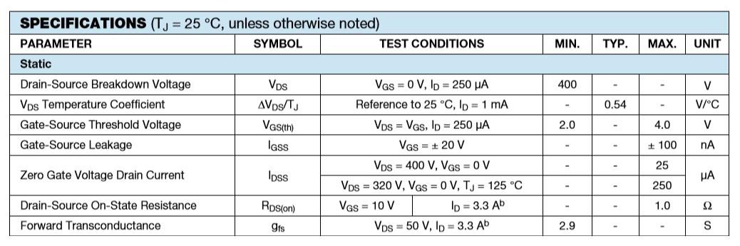
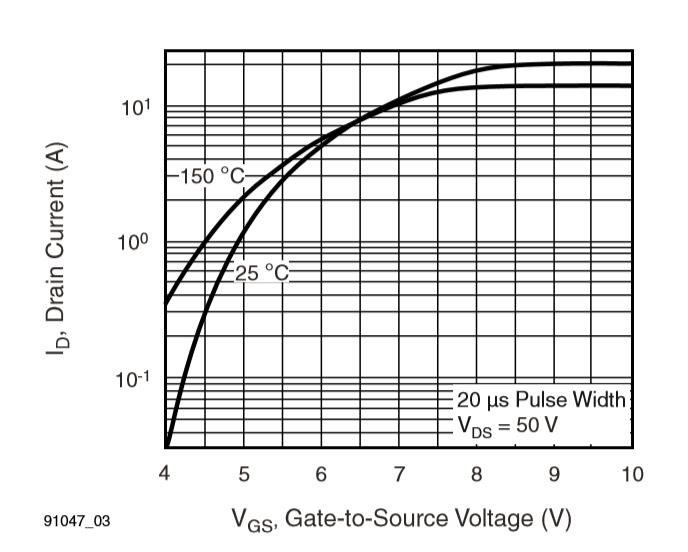
To control the On Time and Off Time, Positive Voltage to the Gate ( 1 ) must reach the rated Voltage Difference between Source ( 3 ). This is seen as VGS on the Datasheet. IGSS is the Current that leaks from the Gate, to the Source, at a Specified Voltage, in this case 20 Volts. Most Mosfet's switch on at around 2-4 Volts but do not Conduct Fully until around 10 Volts.
Marathonman is correct, the Mosfet has an Internal Resistance: RDS(on) In this case, 1Ω but this is when the Mosfet is On. In between this Resistance may be quite different. Turning the Mosfet on fully, and them off fully, is ideal to reduce heat problems!
Needing a Gate Voltage of around 8Volts+ to turn the Mosfet On properly.
This example is of the IRF730:
The Mosfet has an On Time and an Off Time Delay:
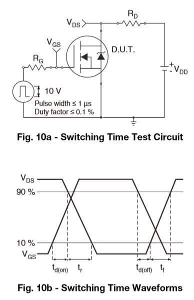
Turn On Time is td(on) and Turn Off Time is td(off). This is the Datasheet Rated times for the Mosfet. However, the Datasheet does not show the Circuit required to turn Off the Mosfet!
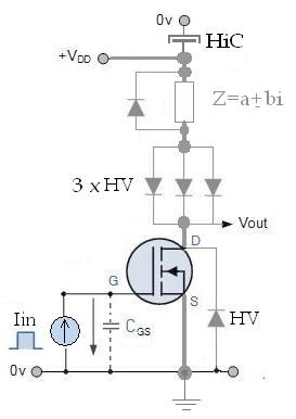
It is possible to Latch the Mosfet, meaning it will stay ON, the Mosfet will not turn Off, unless it has a proper turn off circuit. This is called, normally, a Pull Down Resistor.
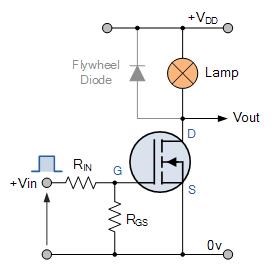
RGS is the Pull Down Resistor, in this instance, Resistance ( R ) from Gate ( G ) to Source ( S ). The faster turn Off Time you want, the lower the value of the Resistor needed. The Mosfet has a Gate Capacitance. Power is required to Charge this Gate Capacitance, this means, this Power must be Discharged, from the Gate Capacitance, to turn the Mosfet Off.
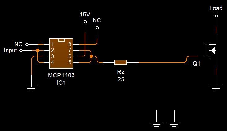
Some Mosfet Drivers have the built in ability to turn the Mosfet off. The IC does this by dumping the Gate Capacitance Power to Ground. It does this very fast! Here is a basic Circuit showing this switching or discharging to Ground:
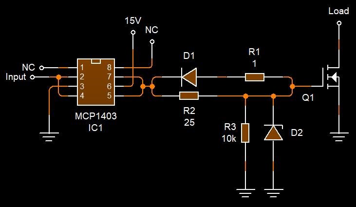
The Mosfet is turned on by this Circuit, through the 25 Ohm Resistor ( R2 ):
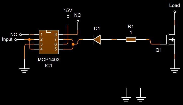
The Mosfet is turned Off, by the Diode ( D1 ) and the 1 Ohm Resistor ( R1 ):
The Mosfet Driver IC has an internal Diagram like so:
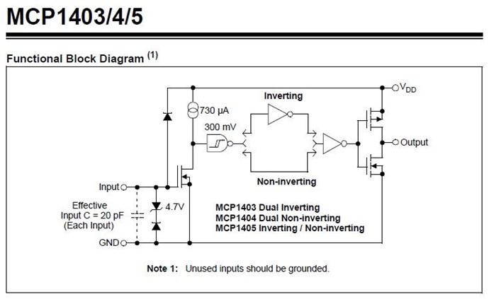
You can see, the IC MCP1403 in this case is dumping the Gate Capacitance Charge to Ground through the Diode D1, the Resistance R1 and through the Internal Mosfet seen in the Diagram above.
I have built one of my H-Bridges from this type of circuit:
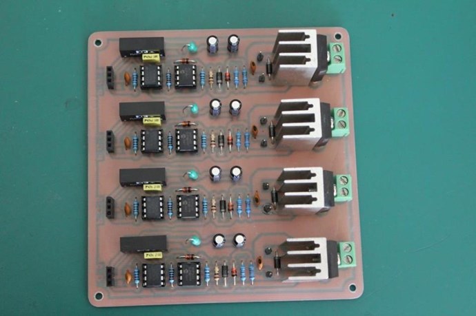
For more information see: Reliable and Flexible Switching System
So, in this example, we can see, Conduction is a factor at which we can very easily change at will! We only need Voltage and a little bit of Current as a result.
I hope this helps!
Chris