Вопрос такой: Как найти секретный параметр транса ?
Из букваря ТАНКА.... 
TAHK пишет:
Транс при наличии хотя бы одного кз витка помнит предъидущее состояние. И сердечник размагничен, и тока в витке нет, и ждать можно хоть неделю. Но анизотропия сохраняется, и только для первого импульса. Если напряжение подано в том же направлении и ему есть куда деваться, например стоит кондер, то он и зарядится сразу. А если напряжение противоположно, то оно сначала падает на индуктивности, притом дольше обычного и конденсатор не заряжается или слабо, происходит только выключение состояния. Что это за "артефакт" и где он живет? Т.е. это память индуктивного сопротивления, но только для первого импульса. Фантом называл "пупырышек". Но этот эффект настолько яркий, если напряжению есть место, что становится триггерным. Завтра нарисую схемку.
TAHK пишет:
Электроны.. электроны.. не забивайте голову 
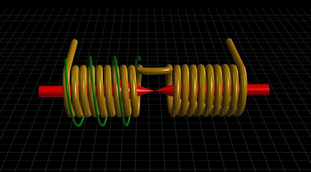
Возьмем ферромагнитный стержень с двумя обмотками, прилепим по бокам магниты так, чтобы стержень вошел в насыщение. На первичку подадим ЭДС в таком направлении, чтобы ток создавал магнитное поле противоположное полю магнитов и сердечника. В таком случае первичка имеет индуктивное сопротивление, на котором происходит падение напряжения - а точнее излучение напряжения в пространство. Пространство отвечает - уже его напряжение "осаждается, улавливается", наводится на вторичке, возникает ток. Ток вторички будет создавать магнитное поле сонаправленное с полем магнитов и сердечника. Это означает, что индуктивного сопротивления для тока вторички нет. Грузим вторичку по полной. Какой бы ни был ток во вторичке, для первички индуктивное сопротивление как было - так и останется. Магниты и сердечник - средство, первичка с напряжением - активатор (модулятор) пространства, вторичка - сток. Слишком просто - потому и в голове не укладывается. Но чтобы так заработало - нужен маленький шаманский бубен, в него ударить надо один раз - "заколдовать" сердечник.
TAHK пишет:
Мда, знатоки теорий рулят, вот только не работает теория при параметрическом стимуле. Работает напряжение, этот
"неуловимый Джо".Допустим есть у нас "индуктометр", что он покажет при намагничивании сердечника? Он покажет "среднюю температуру по палате" - индуктивность упала. Но, он не покажет разбаланс. Что меряет амперметр? Напряжение на шунте? Напряжение на токовом трансе? Или напряжение на датчике Холла? Что вообще такое ток, если его нет для приборов, если ток не может течь и двигаться?
TAHK пишет:
В обычном трансе при обычном режиме фантом тоже существует, но не проявляет себя так ярко потому, что он "согласен" или "доволен" работой первой следящей системы, точнее - он просто дублирует ее. Если научиться блокировать фантом, то никакой резонанс не понадобится. Выше я приводил схему (два транса, три кондера) с туманным описанием. Там суть в том, что трансы держат информацию о начальном индуктивном сопротивлении, притом информация не стирается ни отключением источника, ни переменным током, ни магнитным полем. В момент коммутации получается, что фантом запаздывает в своей реакции и возвращается в исходное при отключении источника, но уже активное состояние. При этом он активен долго, я ждал сутки - и он не изменился. Понимаете, почему полная копия работующего БТГ не заработает сама? Вся магия заключается в блокировке фантома...
TAHK пишет:
Не надо торопиться. Как видите существует и второй уровень защиты - фантомный. Чтобы своими силами построить бтг - надо научиться думать так, как думал тот, кто сделал фантомный барьер. Иначе никогда не понять механизм работы бтг. При непонимании научить повторению придется на уровне последовательности действий. Но никто не обезьяна, поэтому всегда будет вопрос - а это еще зачем? А если кто согласен на алгоритм действий - то кто он, обезьяна или разум? При сохранении и передаче знаний на уровне алгоритма действий - способность мыслить вырождается с каждым поколением. Я убедил вас, что лучше думать о том, почему ток вторички ограничен? Как блокировать работу фантома? Как и чем управляется и т.п.
TAHK пишет:
И чего это бубен так всех заинтересовал? Описал простейшее устройство и все согласны, что это должно работать? Да,
должно.. Все ведь по фен-шую, ой - по Фантому Делаем - а вот фигушки, не работает.. Вернее работает, но ток вторички не превышает тока первички при равенстве витков. Меряем маг поля - ну не меняется направление поля сердечника. Почему ток ограничивается? Во что он упирается? В индуктивное сопротивление? Так ведь нет его! Ток вторички упирается в "бубен". В тот подуровень сердечника, о котором никто не знает. Происходит так, что ограничиваются уже оба тока. Т.е. вариантов два - либо сердечник исчезает, либо появляется виртуальный фантом сердечника, который намагничен уже противоположно. Первый вариант отпадает, мы видим сердечник на месте , первичка его тоже видит (иначе бы ток не испытывал индуктивного сопротивления). Получается, что возникает фантом... А кто знает много о фантоме?
TAHK пишет:
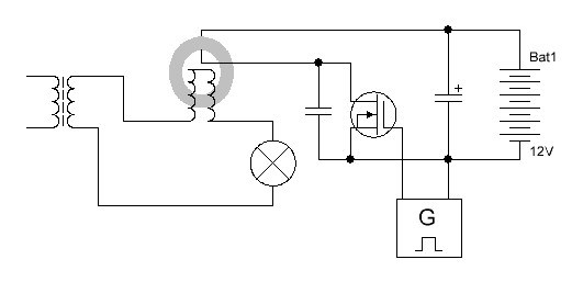
При включении источника - начинаются биения, схема пытается войти в резонанс. После некоторого времени один из трансов станет работать в резонансе, второй нет. Если к точкам 1 и 2 подключить подмагничивание в любой полярности, то оба транса будут в резонансе. Выключим, разрядим кондеры, разомкнем на мгновение вторички. Если заранее зарядить С1 и С2 и на секундочку разомкнуть вторички, то при включении будет тоже самое, только кондеры работают в одной полярности, оба транса не запускаются вместе. Выключаем, запоминаем полярность С1 и С2, замыкаем любой из них, второй разряжается через трансы. Включаем - оба кондера заряжены уже в другой полярности и резонанс на обеих трансах. Теперь резонанс возникает всегда. Можно отключить кондеры, разрядить. Включаем - все вернется обратно, кондеры в одной полярности. Кз обмотки на работу не влияют, но сохраняют состояние трансов, для источника при включении их индуктивное сопротивление разное. Помню.. интересно, что даже переменкой "вытряхнуть" трансы из состояния не получается, а должно.
TAHK пишет:
Электроны.. электроны.. не забивайте голову
Возьмем ферромагнитный стержень с двумя обмотками, прилепим по бокам магниты так, чтобы стержень вошел в насыщение. На первичку подадим ЭДС в таком направлении, чтобы ток создавал магнитное поле противоположное полю магнитов и сердечника. В таком случае первичка имеет индуктивное сопротивление, на котором происходит падение напряжения - а точнее излучение напряжения в пространство. Пространство отвечает - уже его напряжение "осаждается, улавливается", наводится на вторичке, возникает ток. Ток вторички будет создавать магнитное поле сонаправленное с полем магнитов и сердечника. Это означает, что индуктивного сопротивления для тока вторички нет. Грузим вторичку по полной. Какой бы ни был ток во вторичке, для первички индуктивное сопротивление как было - так и останется. Магниты и сердечник - средство, первичка с напряжением - активатор (модулятор) пространства, вторичка - сток. Слишком просто - потому и в голове не укладывается. Но чтобы так заработало - нужен маленький шаманский бубен, в него ударить надо один раз - "заколдовать" сердечник.
[b]БРАТ ТАНК, Совершенно все верно, но из лабиринта нужно выходить спиной.[/b]
Все из головы эта фраза не выходит. ТРАНС спрятан за лабиринтом, к нему идти нужно спиной т.е. или от него в этот мир спиной. Мы сейчас находимся в лабиринте, из которого нужно выходить спиной. У меня есть соображения. В матрице вход в 7 мерность обозначен как вход в зеркало, то есть, можно предположить, что ТРАНС (и мы) в зазеркалье. Если все вокруг одно большое ЭНЕРГЕТИЧЕСКОЕ ЗАЗЕРКАЛЬЕ , то и делать нужно обратные действия - (против матрицы) , потому как движение вперёд - это углубление в зазеркалье. Если мир - зеркало , (а есть) - которое отражает наши мысли , наши действия, отражает действия ТРАНСА, значит, для того что бы выйти из зазеркалья т.е. блокировать работу фантома (ТРАНСА) , надо сделать обратное, например перестать думать по матрицы (шаблонами) или думать в обратном направлении на 180 гр. Лабиринт ещё сложнее, если он зеркальный. Благодаря теме зеркал, в памяти всплывает подвиге русича Персея, который убил медузу (блокировал фантом) используя полированный медный щит как зеркало.
1. Как блокировать работу фантома ?
БРАТ ТАНК - зазеркалым фантом. Дам то что фантом т.е. Матрица не хочет увидеть - "медный щит".
2. Как и чем управляется фантом и т.п. ?
БРАТ ТАНК - мы в матрице. В ЗАЗЕРКАЛЬЕ. Фантом управляется МАТРИЦЕЙ.
эы - БРАТ ТАНК из матрице нужно выходить спиной.