ansen
posted this
03 December 2022
- Last edited 03 December 2022
Hi everyone,
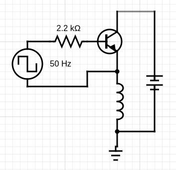
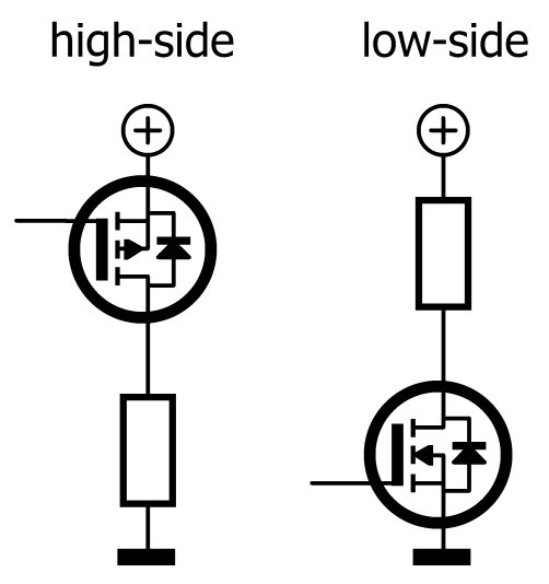
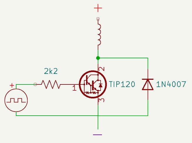
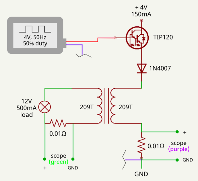
So the switching module finally arrived, but the switched output was really dirty, so I decided to do the switching with a TIP120.
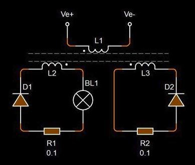
But I'm really getting odd results with current measurement. I currently have a symmetrical setup (for testing).
Current sensing resistors are 0.01Ω, probes are set to 1x, scope to 100x. (0.01Ω x1 x100 = 1Ω)
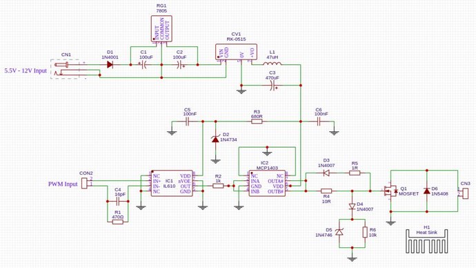
Schematic of setup:
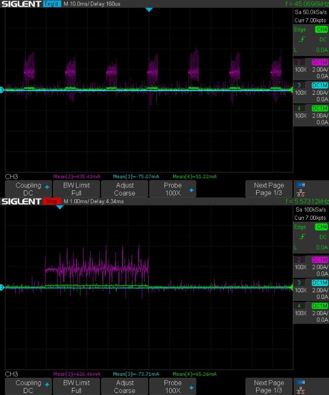
Scope shot (purple is input, green is output:
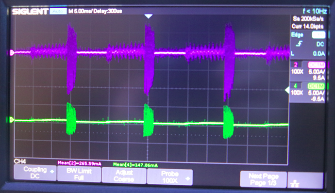
So for the input it should be showing ~150mA, (it's actually showing 265mA) that's what my power supply is saying and I also confirmed it with a multimeter. The output current value is pretty accurate though.
Also there's a ton of noise in there. Is that maybe because I'm partly using alligator clips?
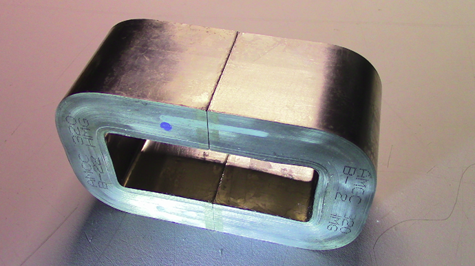
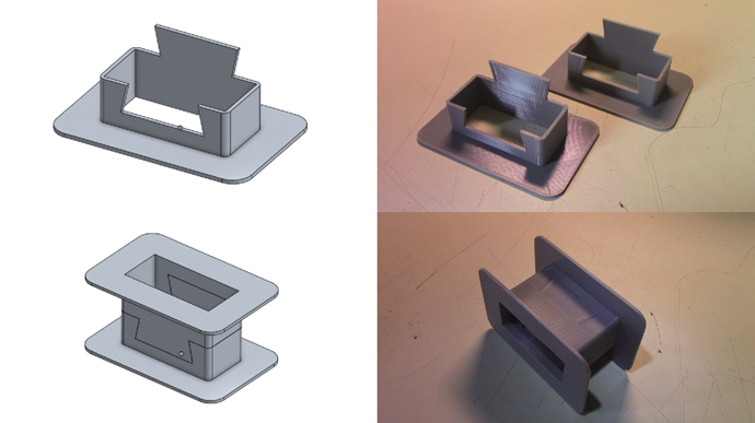
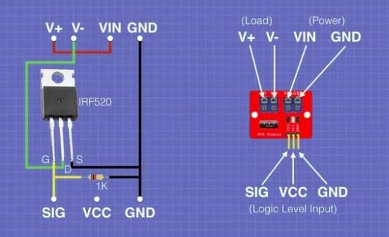
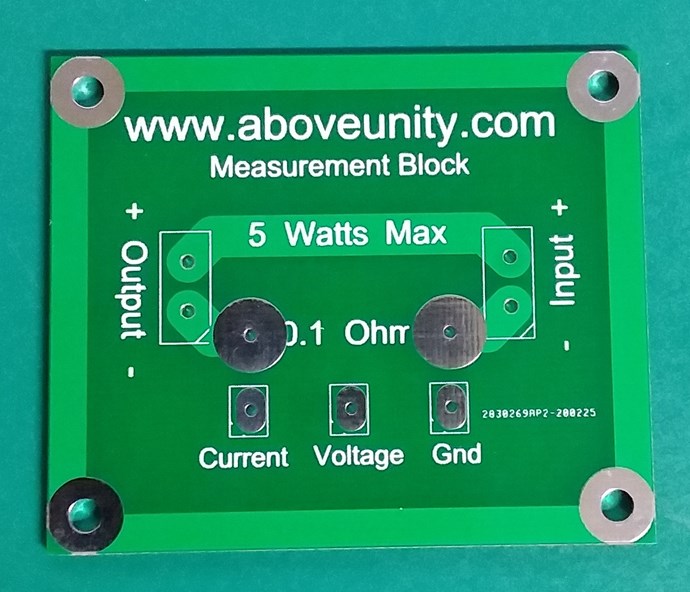
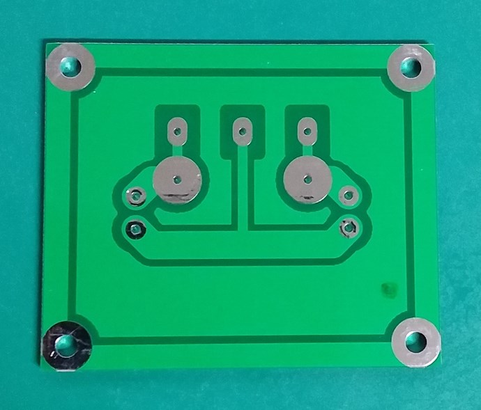
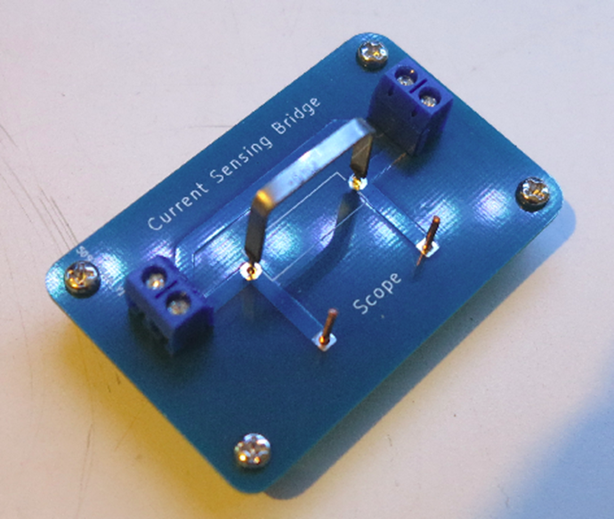
And here's a pic of my current measurement board:
I'm by far not an electronics expert or circuit designer, so if you have any better ideas or comments I'm ready to listen.
Regards,
ansen