

Hello Friends, It occurred to me to post some lines regarding the measurements of Devices under Test, and want to invite all who are interested to discuss in this thread opinions, suggestions, techniques of measurements. Most Researchers know that testing of in and output power, COP and efficiency is an important tool when working on AU Devices, but also that it can be very tricky to achieve really reliable results. For this reason it would be helpful to elaborate the best possible convention for trustable measurement techniques and practice. Vidura
Measurements
- Topic Is Sticky
- 9.6K Views
- Last Post 02 November 2022


Chris
posted this
21 July 2019
- Last edited 21 July 2019
My Friends,
Vidura is right. When Experimenting, I have always said look for the Effects, they will lead you to a greater understanding.
However, when making COP Claims, we must be sure to be accurate, to not kid ourselves and not mislead others.
If your not sure, then leaving an open ended statement is damaging for Us, our credibility, making a statement of "I got COP = 1.3" or what ever and not backing it up with any data does make us look like ammeters and we will be laughed at.
So please, we have Measurement Protocol on this forum, and it needs to be followed!
Many here are very skilled and can help if you need help with measurements!
Resource: Measuring AC Power. DC Power is easy just: V x I with big smoothing Caps.
New Rule: Any COP > 1 Claims must be accompanied by Measurements please!
Chris
- Liked by
-

-

-


Fighter
posted this
22 July 2019
- Last edited 22 July 2019
Hi Chris,
DC Power is easy just: V x I with big smoothing Caps.
Not really. I also thought the same that's why I trusted my DC source's readings because I checked it regularly with diverse loads and always it did shown correct readings.
Remember we're researching devices which according to current physics shouldn't exist and the measuring instruments on market are made according to the current physics. Take a look at the following video where all the readings are correct on all instruments (including the DC source's readings) with a usual load until I connect the ZPM then all the readings (using various measuring methods) become very different.
For now no matter how many big caps and diodes I put on DC source's output the readings are still different. So here I have no doubts about the output as I see 2 x 12V/55W light-bulbs shining, as I didn't expected here is a problem measuring the input. I was as sure as you about the easiness of verifying input.
However, when making COP Claims, we must be sure to be accurate, to not kid ourselves and not mislead others.
I'm not here to mislead anyone. I presented my reasons at the beginning of my thread. I have so little free time I would never waste it doing this (not even talking about the money spent on this).
I put all the data I have here, spent a lot of time presenting it in details including videos and asked others to try, to prove me right or wrong. Nobody tried to reproduce it.
Testing it with different power sources and measurement tools would be helpful, it's called third-party validation. It's not possible for a single person to make so may suggested experiments in so many directions, that would be a 24 hours per day full job. What we do here is to present our experiments and our conclusions (which could be right or wrong) so others can try and have their own conclusions.
These devices can only be fully validated when others reproduce it, there is no other way. I was silent a long time here and decided to post only when I was 100% sure based on the data I had at that moment.
To be honest I never imagined there could be something wrong with the input readings, my concern was to find a way to get exact numbers about the output. Even now I'm not 100% sure there is something wrong with the source's readings, actually on input I have 3 different readings from 3 different ways of measuring the current. Still looking for ways to find which reading is correct.
So I will continue my experiments and present them here in the ZPM thread so others can try, just wanted to present my point of view about this topic.
- Liked by
-

-
-
-

Chris
posted this
22 July 2019
- Last edited 22 July 2019
Hey Fighter,
I believe, reading back, you did not make any COP > 1 Claims, you said:
I'm creating this thread in order to present a device which I think is a overunity device.
Clearly stating you weren't sure.
Please, what I wrote was not about you, its a safety net, so all visitors can be assured when visiting, if a Claim is made, then they can be sure we have done the best we can to verify it.
Don't worry Fighter, I very much appreciate your work and the way you presented your work!
My statement is just so we are all protected and all taken serious! I am sure we all want this do we not?
Chris
P.S: I believe your device is one of the best we have presented, so any out there wanting to learn more, your ZPM is the best place to start after The Mr Preva Experiment.
- Liked by
-
-
-
Fighter
posted this
22 July 2019
Thank you Chris. Considering the troubles I have in determining the input as you can see in the latest video (about output I'm very sure it's a lot of power there), I was thinking the post is related to the experiments I presented, sorry it's 6:12 a.m. almost morning here (worked on presenting the tests I've made in weekend) so for sure my mind is far from fresh right now 
I agree about the necessity of finding methods for accurate measurements, as you can see my video is a first and clear example of the issues encountered with this kind of devices even when making DC measurements...
- Liked by
-
-
-
Fighter
posted this
22 July 2019
- Last edited 22 July 2019
Question: if our fancy digital measurement instruments are so unreliable when dealing with high-frequency, pulses etc. what about using analog devices like this ?

Are they reliable ? I mean we don't need measurements with 3 digits when we're experimenting. Does something like this with an adequate current-sensing shunt be more reliable ? I never used something like this but I just bought one, it's 5A but I don't think it can withstand 5A directly so I should find and adequate shunt for it. Does it need to be tested and calibrated with that shunt ? What if I can't find a 5A shunt, could it work with let's say 10A shunt ? Should it be re-calibrated ?
The reason I'm asking this is because if analog measuring devices via shunts are reliable I'm thinking about making a custom DC source with incorporated measuring circuits which could be trusted in any conditions.
I mean if we're experimenting with devices Tesla worked on and our fancy digital measuring devices are not reliable why not using analog measuring devices like Tesla used ?
For example I could take an auto-transformer like this:
https://www.conexelectronic.ro/en/autotransformatoare/15369-AUTOTRANSFORMATOR-REGLABIL-2-8-A.html
put an adequate bridge rectifier on it then on output I can have shunts connected to digital but also to analog voltmeters and amperemeters, everything packed in a adequate case with a panel where analog plus digital readings can pe shown. Also it can have direct AC output which can be useful when needing a specific AC voltage for experiments.
Of course if would cost and take time to build but it's worth it as long as the result would be a platform with accurate readings no matter what kind of device it's powering.
So the question is: is analog devices + shunts combination reliable ? would be reliable (in terms of readings accuracy) a custom source like the one I just described ?
- Liked by
-

-
-
Vidura
posted this
22 July 2019
Hey Fighter, This simple coilwound meters can be a good choice when dealing with DC currents, although of these have transients components, spikes or high frequency components. They can be used with shunt resistors to adjust the range. Note that this instruments are basically for DC , in order to measure AC a rectifier and filter have to be connected. This can be quite good for frequencies up to several kHz, if components are accordingly selected. But of we deal with very high frequencies it becomes tricky due to increased sensitivity to parasitic inductance and capacitance. Also most components are limited regarding their high frequency capability. Regarding the autotransformer, it is only for a very limited frequency range, for example mains frequency. But the former method with the simple meter, combined with a simple capacitor-choke filter should be fine for a reliable input measurement on the input of your ZPM module. Although the readings will be more broad , not so much resolution, it should be enough for a estimation of real input power. Regards Vidura.
- Liked by
-
-
-
Fighter
posted this
22 July 2019
Hi Vidura, thanks for the explanation. The custom source I was thinking about is actually a DC source with variable voltage driven by that autotransformer + bridge rectifier. On the output of the bridge rectifier I would have shunt and in parallel on that shunt I would have digital + analog ampere-meters. Also it would have digital + analog voltmeters on output. So if in case the device powered on by the source is making the source's digital measurements inaccurate (like in my case now) I will still have reliable readings on the analog amperemeter and voltmeter. Additionally (if needed) I would an AC output with variable voltage but with 50Hz frequency taken directly from the autotransformer. So could I count on the analog voltmeter and amperemeter on the output of the source to be immune to pulses, ripples etc. which could come back to the source from the device it's powering on ? I'm talking about DC output which with my actual DC source seems to mess up with the digital measurements I'm using to check amperage taken from the source (as you can see in my video posted here the readings from source, amperemeter and voltmeter put in parallel with resistor - all are showing dramatically different amperage values). I mean let's say if I would have also analog amperemeter plus voltmeter on the panel of my actual DC source would they show correct values and be immune to the problems the digital amperemeters and voltmeters have now when I power on ZPM and try to make measurements ?
About using filter as you can see in my video I tried with a Schottky diode on the source's positive output plus a big electrolytic capacitor in parallel on the source's output but the digital measurements on amperage are still messed up - big differences between what the source is displaying, what the amperemeter is displaying and what the voltmeter in parallel on that 1MO resitor is displaying. What about the capacitor-choke filter, how would this filter should be built ? I have some small torroidal ferite cores, I can use them to make a choke coil, how many turns and what wire diameter I should try to eliminate the problem I have when measuring DC amperage with digital instruments ? Thanks for your explanations.
- Liked by
-
-
-
Vidura
posted this
22 July 2019
- Last edited 22 July 2019
When we are working with devices using frequencies of several hundred kHz we have to take in account that currents will not necessarily take a closed path as one would expect. At this frequencies one wire transfer of power is common and earth ground plays an important role as well. After watching the video of your measurements I would suggest isolating the powersupply and measurement stage for the ZPM with two chokes, one on the positive and one on the negative wire , followed by two different capacitors, one electrolytic type as you used and one or more smaller ones low ESR type(tantalum, ceramical), near the device under test. With this technique it should be possible to block high frequency transients to a mayor degree. The chokes should have wire gauge according the expected maximal current, the number of turns depending some on the core material , more turns will block down to lower frequency. You can give it a try with what you have at hand anyway. And yes the simple analogue meters are much less prone to react to transients and HF components. If using shunt resistors better avoid wire wound type, as they have more parasitic inductance. Another observation: the continuously changing values on the supply display is typical when HF interference is present on digital meters. I hope this helps something. Vidura.
- Liked by
-
-
-

-
Fighter
posted this
22 July 2019
Thanks Vidura, yes, your explanations helps me a lot to figure out what's going on and how to address these issues. I will read your answers multiple times to make sure I understand them and I'll try your suggestions.
- Liked by
-
-
-
Chris
posted this
23 July 2019
- Last edited 23 July 2019
My Friends,
I think we need to take a step back.
Fighter has shown a machine that is doing a lot of things, the most important thing is that it is interfering with the Power Measurements! At least it is interfering with the Power Measurements with the Digital Multimeters. Again a common problem.
With Precision Metal Film, Metal Strip, or Carbon 0.1 ohm Resistors and an Oscilloscope, accurate measurements can be taken.
Fighter will get to this when time and resources are available.
Fighter and Vasile are right, the Globe will no doubt be close to some sort of Approximation.
From my understanding, this thread was meant for those that were loosely throwing around COP > 1 statements in their Posts?
Please remember, Fighter did not do this.
Chris
- Liked by
-
-
Vidura
posted this
23 July 2019
Chris is right , we can use shunt resistors and a oscilloscope for accurate and reliable results, if measurement for DC (also with HF components) and AC sine waves is required. Some more advanced scopes also have math functions integrated to get RMS values for other than sine shaped waveforms. Specially on the output of many devices we will get composed waveforms, or harmonic distortion. If we don't have equipment to make correct measurements of composed waveforms, a good and cheap method is the calorimetric measurement, which is by the way widely accepted in the most orthodox scientific community. If we we have a device that outputs a complex AC wave, and maybe hardly can be rectified or filtered we can use a resistive water heater with a convenient resistance (similar to our load) measure the start and end temperature in a given time interval, using a scaled amount of water. Then we can calculate with good accuracy the exact power dissipated by the resistance in the time interval. We can use the specific heat of water, with is 4.186 w/s to rise the temperature of 1g water 1°C. Although the actual value is a graph depending on temperature , the deviation is very small, and if we keep the temperature for measurements between 25 and60°C the error will be less than 1%. Water heaters are available for a broad range of power , and different voltages. But when used for calorimetric measurement the only value that is important to us, is the impedance (resistance) to Mach the requirements of our DUT. Regards Vidura.
- Liked by
-
-
Fighter
posted this
28 July 2019
- Last edited 28 July 2019
Hello Fighter,
This is in response to your video:
I will post some suggestions and some questions. I hope you will take them as constructive as posible because this is how they are intended.
Hi Vasile, no problem, any suggestion is welcome, the only problem is I don't have enough time to test all the suggestions, that would be a full-time job, that's why I'm sharing the information in my thread, hopefully others will duplicate the device and make experiments in different directions as they want.
1)At 03:41 in the video it says 1M Ohm. I think you meant 1 Ohm. Correct?
That's correct, it's one ohm. In the same video you'll notice I was saying miliampers instead of microfarads when talking about that capacitor, I was kind of tired when I made the video, my apologies.
2)At 06:19 you say the luminosity of the light bulb is confirming you have close to the amperage your source is showing, meaning close to 0.060 mA. It is best not to judge amperage value virtue of the luminosity of the bulb, because it can be misleading. You are using DC in that example, so I can tell you have at least 1Amp flowing thru it. I atached even a picture with a 12V, 55 W bulb. You can see it draws way more than 1Amp. (Picture atached)
3)Again at 07: 32 you make the same asumption like at 06:19.
I was saying that between the 3 readings I had (DC source's display, amperemeter and voltmeter on shunt) the closer reading would be DC source's readings based on light-bulb luminosity. I saw your photo, the problem there is you have no voltage even if you have current; in my case I'm pretty sure I have 24V on input as you can see in this video:
Those two light-bulbs in series confirm that on the output of the DC source is in fact 24V and the voltage displayed by the source is not wrong.4)At 09:49 you say why different readings between all the equipment? You have a 1 Ohm resistor over there, but lets suppose that it isn't exactly 1 Ohm and it is ±0.1 Ohm, you will have a diferent voltage reading which will lead to a different amp reading, which evidently would be wrong if judged as a 1 Ohm resistor. Another point would be that the majority of multimetres, as you have, measure well only up to 15-20 KHz. The really expensive ones can measure over that and even then only to 50-100KHz range. To solve this problem you need an osciloscope which goes up to MHz as far as voltage readings are concerned.
Don't foget there is DC on the output of the DC source. Even putting a filter made from one fast Schottky diode and a big 10,000uF/60V electrolytic capacitor on DC source's output while making measurements will not change the readings; so why talking about measurement instruments having issues at KHz when they're actually measuring DC ?
Conclusion:
1)My conclusion is simple. Your power source does not indicate well Amperage and maybe even Voltage. Why? It appears your S.G. and/or the black box transistor thing you have there plays the biggest role. Either the high frequency of the switching is messing up with the reading or you have a common ground issue where power flows from the P.S. positive thru either one or both of the S.G. and/or the black box, to ground.
All the best,
Vasile
I just shown in my previous video that the DC source indicate voltage correctly. Also with that noise filter the amperages indicated by DC source and other measuring instruments remain the same so the cause of different readings is not the noise coming back. The "black box" meaning the MOSFET driver is not connected to the power grid, it's connected only to the DC source's output so there is no power leak through it. Also you should see the transformer in that signal generator, I doubt it can handle amperes leaking to the power grid through it, it would be gone for a long time if that would happen. About the high-frequency messing up with the readings, I already mentioned that I tried with that noise filter and saw no changes. But let's say there is high-frequency on the DC source's output, it should mess with all the instruments not only with the source. Why other instruments show amperes while the source show miliamperes ? Makes no sense. So as you can see there is no conclusion yet on these issues. That's why I'm using my free time to share this information, so others can replicate ZPM and start experimenting with it else there would be just an exchange of hypotheses without real advance. Thanks.
- Liked by
-
-
Vidura
posted this
28 July 2019
- Last edited 28 July 2019
Hello all, Only a brief comment about filters: For an effective filtering of interference in a DC line the LC filter combining inductors and capacitors is a good and effective methodology. There can exist common and differential mode interferences, if we use at least one inductor in the positive and one in the negative wire combined with some capacitors in parallel, we can block both types of them mostly if inductance and capacitance values are choosen according to the frequency ranges. Note that a combination of capacitors and diodes will not block interferences efficiently. Vidura.
- Liked by
-
-
-
Fighter
posted this
29 July 2019
Vasile, I agree with that but that doesn't mean what's powering that bulb is entirely provided by the DC source. Please take a look in the latest updates on ZPM thread, in some experiments I posted there you will see the oscilloscope reading Vpp=240V. That voltage is not provided entirely by the 24 volts of the DC source either. Regards.
- Liked by
-
-
Fighter
posted this
29 July 2019
Vidura, noted, so that diode-capacitor filter is not very efficient. I have on my list to create an inductor-capacitor filter, thanks, will take care of it when I will have some time.
- Liked by
-
-
Chris
posted this
31 July 2019
- Last edited 31 July 2019
Hey Vasile,
Please forgive me, but that's a very long way around a simple problem don't you think?
With some 0.01 Ohm precision Resistors, Fighter could have a very accurate result in about 10 minutes! I have already provided the circuit for measurements: here.
Chris
- Liked by
-
Chris
posted this
31 July 2019
- Last edited 31 July 2019
Hey Vasile,
I understand that perfectly and I want to say something here:
1) If we are talking about measuring after the power source, I think he believes that somehow the power is coming from the ZPM to his power source, so it would be irrelevant measuring like that, because once again, the power could come somehow from the ZPM.
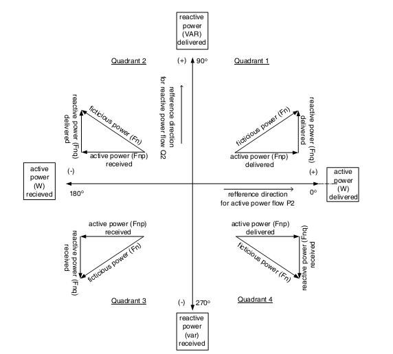
Yes, the Power does reverse. Yes Energy does come back to the Source, its an Impedance and the DUT see's the Power Source as a Load. This Power coming back reduces the Power Input, Reactance, and yes as a result, the Input Power reduces the more load is applied.
Most certainly not an irrelevant measurement, this is an important understanding step, very important.
One can see on the scope when this occurs, as a Power Factor Correction: 0.0 or less:
2)So, I recomended measuring before the power source, like between the plug of the power source and wall power. I didn't want him to go near with his hands on live wires, that is why I recomended the wattmeter. Of course as you said the resistor method would be more accurate.
Yes, a good idea to see what the power is doing. Certainly an experiment that can be performed once more is understood about what's going on. The Input to the Device Under Test ( DUT ) is from the source, and from there, in between the Source and the DUT, the Input Power must be measured:
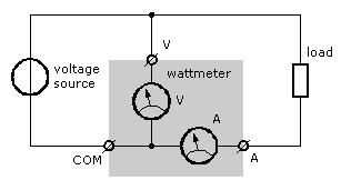
The Power Source must be measured as a separate load because of the condition the Power Source is exposed to. Again, it simply is an Impedance to the DUT.
I have always said, study closely the Currents, the applied Right Hand Grip Rule will guide one from there. Truly, the important thing is the Currents.
I also encourage extreme care with these Devices!
Chris
P.S:
the power could come somehow from the ZPM
If Fighter replaced the ZPM with a Honda 3 Kwh Electric "Generator" would that explain the somehow part? Faraday's Law of Electromagnetic Induction is the Somehow.  No Magic, No Mysticism, please believe in todays Tech.
I hope we have cleared this part up?
- Liked by
-
-
-
Vidura
posted this
31 July 2019
Hey Fighter, I have seen your scope measurements before, there are some odd things actually. It is likely, almost certain that there's an interaction between the DUT and the power source. I have noted that the waveform is changing when you invert the probe polarity. This could be a effect of ground connection of the scope. Maybe by filtering you can get more accurate results, provided that the filter capacitors don't prevent the DUT to work properly. I mean the current would circulate between the device and the filter capacitors instead the powersupply, and actual current and voltage could be measured between the filter and the supply. You should also take measurements of the voltage with the scope, and multiply V RMS and I RMS. Vidura.
- Liked by
-
-

-
-
- and 1 others
Fighter
posted this
31 July 2019
Hi Vidura, but it is recommended to make sure the scope is grounded, isn't ? So I made sure my scope is grounded and the source is floating (not grounded) to avoid blowing up my scope while measuring circuits powered by my source.
- Liked by
-
-
-
-

Jagau
posted this
31 July 2019
- Last edited 31 July 2019
Hi my friends
I use on all my measuring instruments on insulation transformer is strongly recommend.
I also run my oscilloscope on an inverter ,12volts DC battery to 110volts AC, that works very well too,
however, for an oscilloscope, a floating ground is a way to avoid a problem but accuracy can suffer.
So the ground is not linked
Jagau
- Liked by
-
-
-
-
- and 1 others
Vidura
posted this
31 July 2019
- Last edited 31 July 2019
hey Fighter,
Yes it is recommended to ground not only Scopes, but virtually all electric devices for safety reasons, it is not likely that a device will be damaged for using it without ground connection. I use my old CTR scope mostly without earth ground, also the methods proposed by Jagau are correct and can be safely used. Anyway probably when the device is separated from the power supply by a efficient filter it will show a smooth DC like trace on the scope, with or without grounding.
Vidura
- Liked by
-
-
-
Chris
posted this
31 July 2019
- Last edited 31 July 2019
But I already did that (fragment from that post below)
Hey Fighter,
Those Resistors might be Wire Wound Resistors, CD if you can verify the model you bought, that's might be why you see the strange currents. Here is the 15FR250E Datasheet, saying its a Axial Wire, that should be ok.
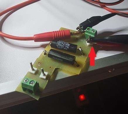
We can not use Wire Wound Resistors at high Frequency, only low frequency. Its a big no-no, so if these Shunt Resistors are Axial Wire, they should be ok.
Another thing to do is shorten your Wires to the machine, short as possible, this might help.
At the end of the day, the ringing just might be a real effect coming back out of your ZPM. Perhaps a Harmonic?
Chris
P.S: Sorry everyone, I made a mistake and Fighters post was accidentally deleted 
- Liked by
-
-
-
Fighter
posted this
31 July 2019
P.S: Sorry everyone, I made a mistake and Fighters post was accidentally deleted
No worries, it's not a big deal
- Liked by
-
Chris
posted this
01 August 2019
- Last edited 01 August 2019
My Friends,
The missing post was in reference to this post: here. Sorry again!
In the below image, we see two numbers with a red line above them:
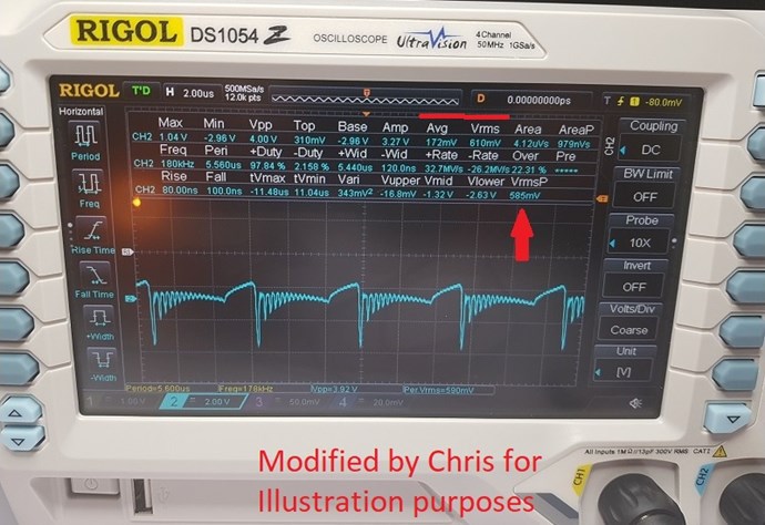
Both numbers are very different! Average or Mean: 172mV and Vrms or Voltage Root Mean Square: 610mV.
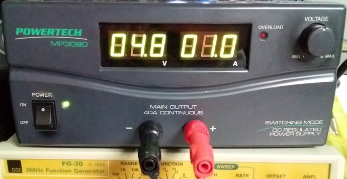
Importantly, we have a DC Power Supply! Direct Current meaning one way only! At lease if one is running a Linear Load like a Light Globe!
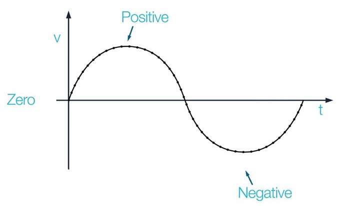
All Current below the faint turquoise line I have drawn in here:
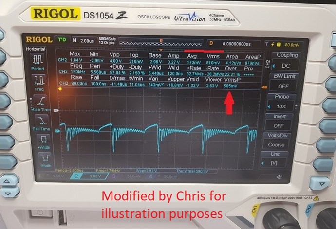
is Negative Current, its below the Zero Graticule Line of the Probe measuring it.
The Root Mean Square is 610mV across a 0.25 Ohm Resistor, this is approximately: 59.512 Watts input to the ZPM.
At the same time the Scope is saying we have 172mV across a 0.25 Ohm Resistor, this is approximately: 17.082 Watts input the ZPM.
Both figures cant be right! So in this case which one do we trust?
We know Power is coming back at us, the ZPM sees the Source as a Load! The ZPM is trying to Power its load, being the Power Supply.
So what do we have? What are the facts?
- 172mV across a 0.25 Ohm Resistor, 0.688 Amps, approximately: 17.082 Watts input the ZPM.
- 610mV across a 0.25 Ohm Resistor, 2.44 Amps, approximately: 59.512 Watts input to the ZPM.
NOTE: RMS is always positive, it does not give an indication of the direction of power. Now, I ask others to correct me if I am wrong! You should use Mean, which is an integration ( Addition ) of the instantaneous power readings ( each sampling point on your screen ) over as many Cycles you have on your screen, which is time, which yields total Energy for this time interval. This is because your DUT is Non-Linear, and your Source is DC, the DUT sending Power back to Power the DC Source! With a Linear Load, and an AC Source, you should use RMS most of the time. Chris
- Liked by
-
-
-
-
- and 2 others
Vidura
posted this
01 August 2019
Good tutorial video, in my understanding basically the mean value would show a DC offset in such a complex waveform, we could define if in average more current flows in one direction limiting the measurement by cursor triggering to one cycle. But what's about the power factor? The real power in any point of the cycle of a sine wave or a complex waveform depends on the phase angle to the related voltage. I guess that the area measurement could be used if the value of the capacitance is known, as in the example in the video, but I don't have experience in this, as I don't have a digital scope. Although this tests can be useful for understanding the behaviour of the interaction of the DUT and the power source, for a input power measurement I would prefer to go a step backwards using a filter , and simply take a reading of current and voltage on the quiet side of the circuit. Vidura.
- Liked by
-
-
-
-
Jagau
posted this
01 August 2019
A good explanation of the difference between mean (average) and RMS
which is to say:
Average value = 0.637 × maximum or peak value, Vpeak
RMS value = 0.707 × maximum or peak value, Vpeak
in terms easy to understand. here is the link:
https://www.electronics-tutorials.ws/accircuits/average-voltage.html
Jagau
- Liked by
-
-
-
Chris
posted this
01 August 2019
- Last edited 01 August 2019
Hey Vidura, Jagau,
@Jagau, thanks for the excellent links!
@Vidura, I agree, yes DC Offset, what is the definition of DC Offset:
DC offset is an imbalance that sometimes occurs in A/D converters ( see WFTD archive “A/D Converter“ ). When working with audio it is desirable to have only the audio program material passed through the signal path. Almost by definition audio, being a periodic waveform, is an AC (Alternating Current) signal.
Ref: www.sweetwater.com
Note: A/D converters = Analog to Digital converter.
Note: Mean or Average can be both Negative and Positive! Unlike RMS, which is only Positive.
The above video shows and states: ( 1 : 07 )
the mean value or average is computed by summing the value of each point and dividing by the number of points.
Because we are using a DC Source, Direct Current, not Alternating over Time in any way, we should only ever expect to see one polarity of Current, but we do not!
NOTE: If Fighter were to measure Zero Mean Current, then equal Current is going out as is coming back to the DC Power Source.
If I can reference the above video again: ( 1 : 16 )
if a signal is as negative as it is positive, that is if its symmetrical around zero, the mean value will be zero.
We see the DUT pushing Current back, already covered. If the ZPM uses zero mean current, then the Energy used in the ZPM is Zero.
The Mathematical function to Integrate ( ∫ ) is just, a series of additions:
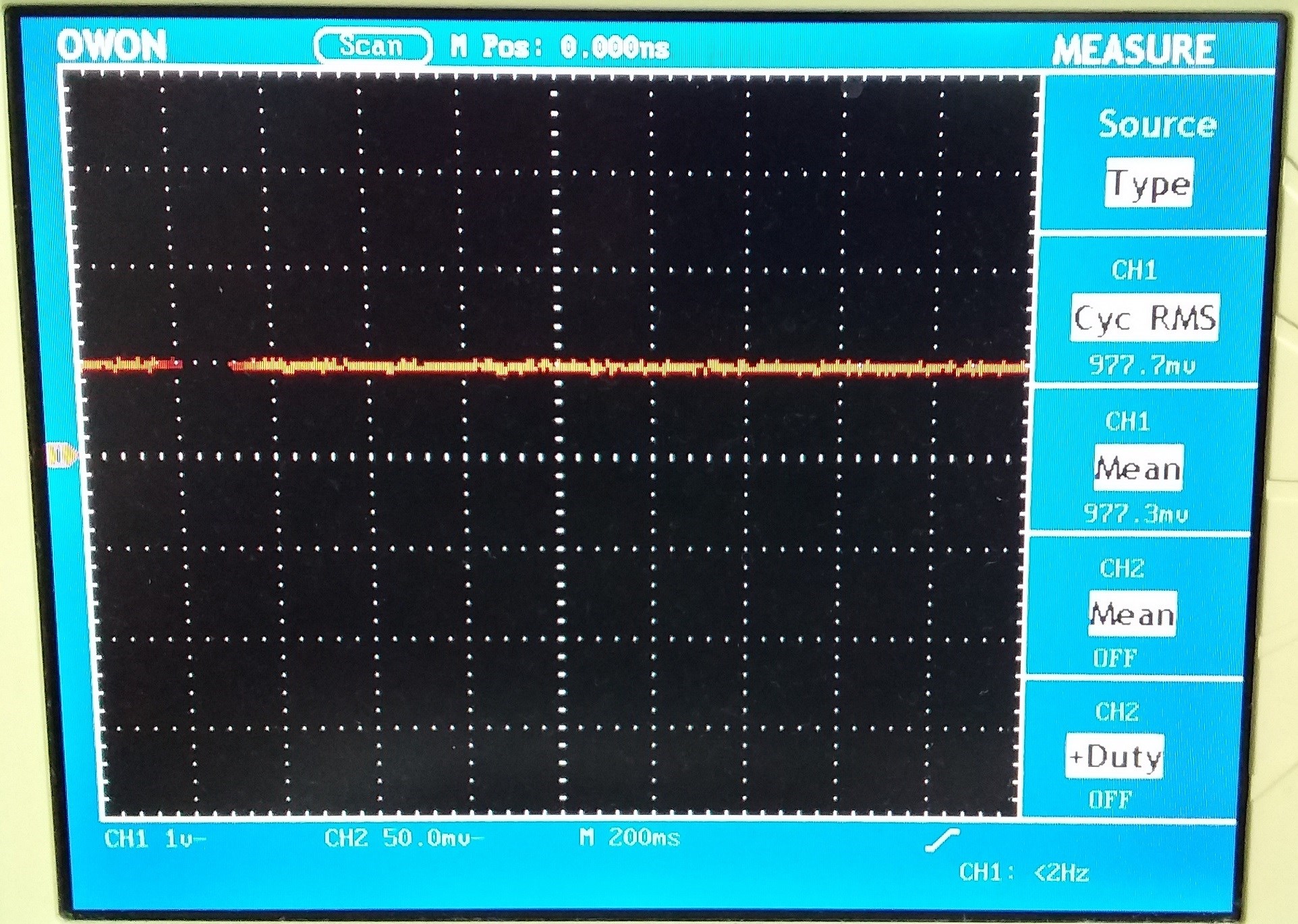
Taking all the Sampling Points the Scope has taken over the time period, adding them all together and dividing by the number of points recorded. When a Scope Samples at say 5GHz per second, a common sampling rate today, that means 5 Gigabits per second are recorded. There are different methods of recording: This guy is awesome! His example: ( ( 5Gs / Sec ) x ( 20μs / Div ) x ( 10 Div ) ) = 1,000,000 samples NOTE: Each pixel, representing the waveform, drawn on the Scope Screen is a Potential Value, its not related to the direction of the Current, in this case, the Polarity, the amplitude above or below the Zero Graticule Line for the Probe, determines the direction of the Current. Meaning if the Value Recorded is Negative or Positive. Our Scope, if all points are Positive, then the Active power from the DC Source will be Positive Power, in the direction of DC Supply to Load. The Average, or Mean of those points over the course of the Scopes Memory captured is the Average power in our case, measuring V and I over Time with Instantaneous Measurement Points. Here is a brief example of the Points being measured with DC and a Linear Load: So what do we have? Scope Probe is set to 1x, but in the scope settings I have 10x set on the Probe. The Sense Resistor, a Metal Strip Through Hole Current Sense Resistor, is a 0.1 Ohms Resistor, so what I read on the Scope is the Current: 977.7 milliamperes at 4.8 Volts = 4.693296 Active Watts, because we have DC with a Linear Load. Remembering: Watts is equivalent to Joules per Second. One Watt = one Joule per second. Energy over Time. Above you can see, RMS and Mean are pretty much the same: 977.7 vs 977.3 mean. With a Linear load, we don't have a problem, but as soon as the Load is non linear, we get a much different story. Again the Sampling Points become Negative, and Current is being returned to the DC Power Source. Not something you would expect to see on average, in a DC Circuit. Chris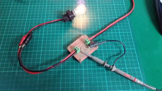
- Liked by
-
-
-
-
- and 1 others
Chris
posted this
01 August 2019
Hey, Chris the resistors Fighter is using are non-inductive. I have been using them for a long time with good accuracy at any frequency.
Thanks for verifying that CD.
We can have Non-Inductive Wire Wound, which we can not use to verify Currents in a High Frequency Machine:
If only the potential was realised?
So all Wire Wound Resistors should be our goal to eliminate from our measuring toolkit.
All components have a little bit of the three base quantity's: Resistance, Inductance and Capacitance We can not eliminate Inductance and Capacitance completely, but we can minimise it! Chris
- Liked by
-
-
-
-
- and 1 others
Chris
posted this
06 August 2019
Guys, this is a repost, for information purposes:
Hey Fighter,
This is correct! The RMS Values are including the Power being returned back to the Source and not giving you an indication of the Direction of Current.
Direct Current, is a unidirectional Current, its not supposed to Alternate over Time or it is then AC, Alternating Current.
The quote goes on:
E.G: The scope records: 0123456789876543210.
Now we Integrate ( Series addition ) : 0 + 1 + 2 + 3 + 4 + 5 + 6 + 7 + 8 + 9 + 8 + 7 + 6 + 5 + 4 + 3 + 2 + 1 + 0 = 81.
Now divide by the number of points recorded: 81 / 19 = 4.26315789.
4.26315789 is the average.
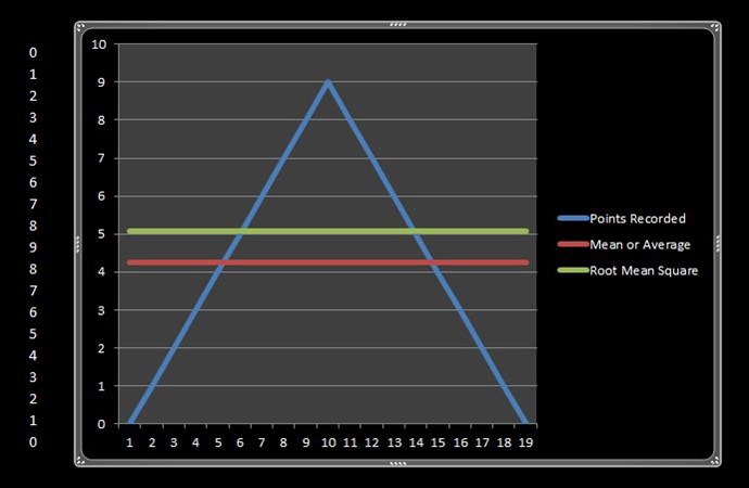
What does this mean? It means we can split the Triangle above the Mean line, down the middle, and put the two sides in the open area on the ends, the area is the same. This gives us a perfect Mean value. The shown RMS Value you can see is well above the mean height! There is no even distribution of the Waveform above the RMS value to the ends of the Wave shape. The area is not equal to the open area on the sides under the line!
The reason straight DC is so easy to measure is because its a straight line:
The area under the Straight Line, the Waveform is a Rectangular Box: H x W = Area. 977.7mV x 1t = 977.7mV
NOTE: The ZPM is a NON-Linear Load.
Now in the ZPM, if we use RMS, we cant include Power coming back as USED Power, which is what RMS power setting is doing! This is wrong!
Also NOTE: RMS is fine for Linear Loads! It will measure almost the same as Mean! See Here.
RMS is Root Mean Square, the equation is fairly straight forward:
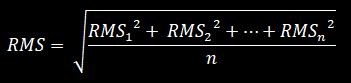
See www.electronics-tutorials.ws for much better information on all this.
So we could say:
int TotalPoints = 19;
double Integration = Math.Pow(0, 2) + Math.Pow(1, 2)
                   + Math.Pow(2, 2) + Math.Pow(3, 2)
                   + Math.Pow(4, 2) + Math.Pow(5, 2)
                   + Math.Pow(6, 2) + Math.Pow(7, 2)
                   + Math.Pow(8, 2) + Math.Pow(9, 2)
                   + Math.Pow(8, 2) + Math.Pow(7, 2)
                   + Math.Pow(6, 2) + Math.Pow(5, 2)
                   + Math.Pow(4, 2) + Math.Pow(3, 2)
                   + Math.Pow(2, 2) + Math.Pow(1, 2) + Math.Pow(0, 2);

double Average = Integration / TotalPoints;

MessageBox.Show("RMS: " + Math.Sqrt(Average));

RMS: 5.07314913098986
Note: a small difference: 5.07314913 RMS vs 4.26315789 Mean, the difference: 0.80999124. The values often vary a little between RMS and Mean, but with a Non-Linear-Load, Mean must be used.
Note: I have used the same numbers in this example, RMS Voltage and Mean Voltage readings on the scope can be different, so please be aware this example is only that, an example.
Note: (81 / 19)2 is not the same as squaring each number and adding.
Again, RMS does not give you an indication of the Direction of Power, the reading is always Positive, the Mean or Average setting is not this way! Mean can be Positive, Negative or Zero. Zero means all the Power you send Out to your Load ( DUT ) You get the exact same back again! 1 + -1 = 0...
For some it may seem impossible, but Electromagnetic Induction really does work!
Now I am not perfect I make mistakes! So I urge you to all do your own research on this! Research how to measure the Area under a Curve ( Scope Waveform ) and find out more on this. I did post several very good videos on this!
Remember: Every pixel drawn on your scope screen, it is a Potential Value Recorded. Millions of values measured then recorded of that Potential over Time. All these values, in the Scope Buffer, indicate Instantaneous Power measured over time, this is the X Axis, the values themselves are the Y Axis, Amplitude.
Some time back I was very lucky, a very good friend of mine gave me one on one lessons on how to use a scope. Thanks Gerry!
I hope the knowledge I gained I am now able to pass on to you so you can also pass on.
Chris
P.S: a better code example if you want to play with this:
double Integration = 0.0;

double[] Points = new double[] { 0.0, 1.0, 2.0, 3.0, 4.0, 5.0, 6.0, 7.0, 8.0, 9.0, 8.0, 7.0, 6.0, 5.0, 4.0, 3.0, 2.0, 1.0, 0.0 };

for (int i = 0; i < Points.Length; i++)
    Integration += Math.Pow((Points[i]), 2);

double Mean = Integration / Points.Length;

MessageBox.Show("RMS: " + Math.Sqrt(Mean));
- Liked by
-
-
-
-
Vidura
posted this
07 August 2019
A suggestion for a simple and good filter for keeping out interference from our measuring devices. The values of the components are not at all critical, but may need some adaptation for the expected frequencies. Ceramic decoupling and tantalium caps for the smaller values perform better. The meters could be replaced by a scope as well.

Regards Vidura.
- Liked by
-
-
-
-
Chris
posted this
09 August 2019
My Friends,
I have put what we have covered into a Video:
It is important to understand what the numbers are, that's being recorded on the scope. Remember, two wires can only deliver Current in two directions, Positive and Negative. The Negative numbers cancel out the Positive numbers and the Mean is only the total difference.
I hope this helps!
Chris
- Liked by
-
-
-
-
Chris
posted this
11 August 2019
My Friends,
This video is a bit long and perhaps rambles a bit, but I hope you find it useful anyway:
Fighters ZPM is an example of what I am trying to outline! Know the capabilities of your Current Source!
I hope it helps!
Chris
- Liked by
-
-
-
-
- and 2 others
Jagau
posted this
06 September 2019
- Last edited 06 September 2019
Hi Chris
an excellent video that I listen until the end
Just a quick note, most of John Bedini's Ing. books carry this mention and I think the same thing.
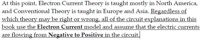
Jagau
- Liked by
-
-
Chris
posted this
06 September 2019
- Last edited 06 September 2019
Hey Jagau,
Thank You! I am glad its useful for you!
Some years back, I did an in-depth study of the way we Humans measure Power. I found that even Electrical Engineers did not have a very good understanding of how Measuring Power properly worked! They get confused and even get it wrong when they are dealing with Non-Linear Loads!
A Non-Linear load, all it means is Power can be sent back to the Source, that's all.
Most EE's do not grasp this concept very well! Even some of the big wigs over on the other forums do not know how to deal with the Non-Linear Load phenomena! Many say use RMS, we have seen, that's just out right wrong if a DC Source is used and we have a Non-Linear Load! Two names in particular come to mind!
Some folks told me, years ago, over on one of the other forums, people are here to help you, they can help with your measurements - That's outright wrong, as they themselves don't know how to measure! See for yourselves: Accurate Measurements on pulsed system's harder than you think.
Even now, Tinman still does not know how to take proper DC measurements, still using RMS measurements with a Non-Linear Load, getting the entire thing wrong! The evidence is here:
I hope everyone can see, why its so important to know some of these simple things! Things that the Trolls would be happy for us to stay in the dark about! Light Up The Darkness! Chris
- Liked by
-
-
-
Jagau
posted this
06 September 2019
- Last edited 06 September 2019
In the system of which I am more familiar "RF measurement"
it is the mean and the peak power measurement which are important
the RMS is not to use it is mainly to use for more linear circuits.
i agree with you
Jagau
- Liked by
-
-

getreal156
posted this
06 September 2019
- Last edited 06 September 2019
Hi Cris and/or others,
For me it also is very confusing and I would love to learn more about this topic.
Is there a source of information that you can recommend regarding non-linear power measurements?
- Liked by
-
-
Chris
posted this
06 September 2019
- Last edited 06 September 2019
Hey GR,
One source, not really, a study is required, reference and then Cross-Reference is required.
https://www.sciencedirect.com/topics/engineering/non-linear-load
https://www.academia.edu/2072975/Design_of_a_Power_Factor_Measurement_System_for_Nonlinear_Load
and sort of carry on from there.
Chris
- Liked by
-
Jagau
posted this
06 September 2019
One of the best video I could recommend is this one
Subsequently in his site there are other video on resonance measurements, but starts with this one
Jagau
- Liked by
-
-
-
getreal156
posted this
06 September 2019
Great. Thanks a lot Jagau and Cris
As I am progressing with my experiments it is about time I learn more about it.
- Liked by
-
-
-
Chris
posted this
06 September 2019
- Last edited 06 September 2019
@All Readers,
I think it is important to re-emphasise, there is a time and a place for RMS and also Mean measurements - We need to know when this time is.
- RMS typically used for an Alternating Current Source.
- Mean typically used with Direct Current Source.
The Load, Linear or Non-Linear must be realised. There is a time and a place for each measurement system, and this is what I am trying to explain, how to identify the need for which System.
Its necessary to identify the capability of ones Power Source.
Any Current in a direction, or a Frequency, that your Power Source is not capable of supplying must be taken into account.
Chris
- Liked by
-
-
-
-
- and 1 others
Vidura
posted this
09 September 2019
Current shunt resistors:
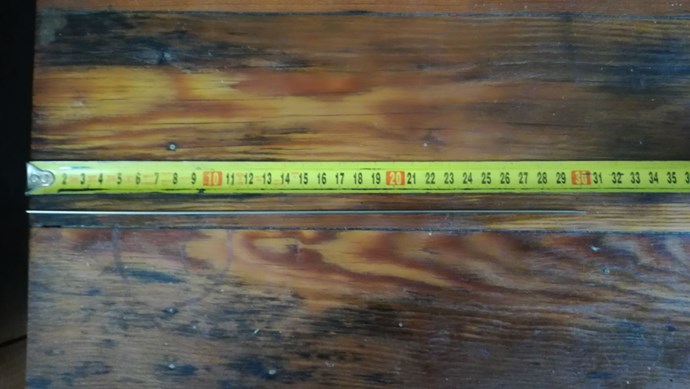
As there where some doubts about the high frequency capability of some types of current sensing resistors I will post this suggestion, i use this sometimes as a cheap and very accurate option: 1.6 mm diameter of 308 grade stainless steel welding rods have a resistance of 0.343 ohm per meter of length. You can make a 0.1 ohm precision shunt using a length of 291mm, and if you bend it in a u-shape nearly all parasitic inductance will be cancelled due to opposing magnetic fields . ( like Atti shown in his ZPM replication video).
Vidura
- Liked by
-
-
-
-
- and 2 others

Fighter
posted this
09 September 2019
... or something like this ?...

They are 10A/75mV shunts and I intend to use them for real-time and permanent measuring system on ZPM's input and output.
I will try to use them with some analog ampere-meters, the only problem is calibrating this system to make sure the measurements are accurate all the time in any conditions...
- Liked by
-
-
-
-
Vidura
posted this
09 September 2019
- Last edited 09 September 2019
Hey Fighter, Yes this shunts are also ok, the stripe shape has very little inductance , a drawback might be the small resistance, depending of course on the measured current., This one will have a voltage drop of 7.5mV @1A. You can test them with DC, although they are factory calibrated. For practical reasons and easy reading without calculations it is recommended to use values like 0.1 ohm,(100mv @1A) or 1ohm (1v@1A)for smaller current values. Vidura.
- Liked by
-
-
-
-
- and 1 others
Chris
posted this
09 September 2019
Well, CD, this is odd!
I am going take a guess and say bad Mosfet, perhaps stray capacitance on the Gate? You truly should not be seeing this, even with wire wound resistors!
Testing both Resistors, do you get the same results?
To me, this just does not look like the Resistors are causing all this noise! It is coming from somewhere else, perhaps even a bad connection in the breadboard?
Upwards of 3 to 10 MHz you might see noise like this, but not this low! 1KHz!
Chris
- Liked by
-
-
-
-

Fighter
posted this
10 September 2019
- Last edited 10 September 2019
I would suggest to replace all the inputs and outputs of the device plus the connection from the signal generator to the MOSFET driver with thicker multifilar wire like I use (you can see it in my photos).
Links:
Don't forget all those coil wires I see intersecting each other are producing high-frequency and powerful enough magnetic fields interfering with each other. That could be the source of the ringings, those coil wires are forming themselves small coils interacting with each other.
The only ringings should come from the device itself.
Just my opinion.
- Liked by
-
-
-
-
Jagau
posted this
10 September 2019
it is a very good idea to use gate series resistors of 1K to 10K.
This is especially important if the Gate signal comes from another circuit board.
If a MOSFET could be left floating then use a pull down resistor (100K to 1M is generally ok) from Gate to Source.
you will avoid many problems like this one.
Jagau
- Liked by
-
-
-
-
- and 2 others

solarlab
posted this
10 September 2019
- Last edited 10 September 2019
Hi CD Sharp,
** Jagua's more than likely correct. **
Might be MOSFET jitter or oscillation due to Gate bounce or noise - the MOSFET is being turned on - off rapidly due to gate trigger threshold being exceeded (noise - probably created by feed-back from the drain - source switching side).
Refer to some FET gate driver application notes for details.
JMHO of course... [but, I'd bet that's what it is !]
SL
- Liked by
-
-
-
-
- and 1 others
Chris
posted this
10 September 2019
Hey CD,
If I may remind you of our thread: On and Off, Conduction in a Mosfet
We looked at properly switching a Mosfet. This should help greatly with your problem.
I hope this helps!
Chris
- Liked by
-
-
-
Vidura
posted this
10 September 2019
- Last edited 10 September 2019
Hello All
Here I will show you how you can make a low cost precision shunt resistor 0.1 ohm made from a 1.6mm 308 grade stainless steel welding rod. First cut a length of 299mm of the rod, 291 mm corresponding to 0.1 ohm resistance, plus 4mm each side for the screw connectors:
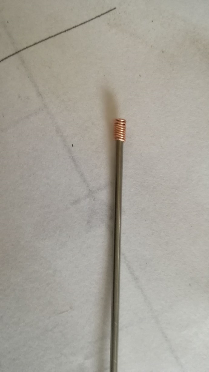
Then wrap several turns of a uninsulated thin copper wire over the 4mm reserved for the connector on each side. This is very important, because if only a small area of the resistive rod is touching the connector, the resistance can increase notably and lead to erroneous results.
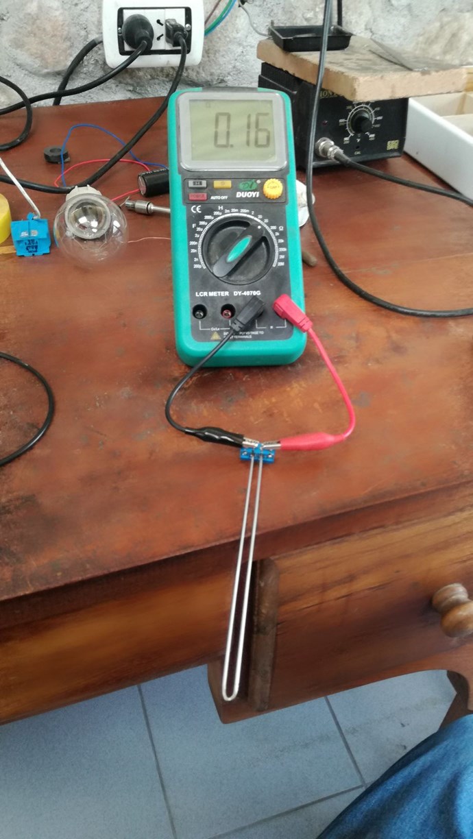
Then bend the rod in the centre exactly to get a U shape like this:
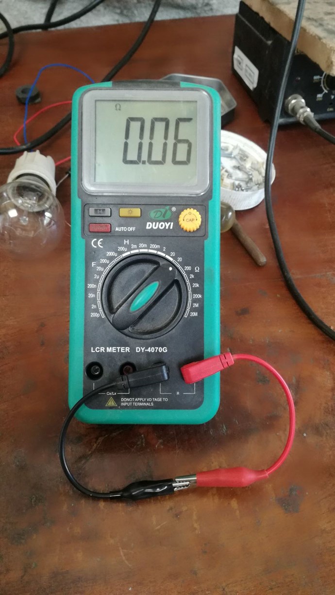
And finally mount it tightly on a screw connector :
- Liked by
-
-
-
-
- and 4 others

We're Light Years Ahead!

Members Online:
No one online at the moment
Past Visitors: 0 | Live Visitors: 0
3D globe widget by: Chris Sykes
Our Above Unity Machines:
Recomended Protocol:
What is a Scalar:
In physics, scalars are physical quantities that are unaffected by changes to a vector space basis. Scalars are often accompanied by units of measurement, as in "10 cm". Examples of scalar quantities are mass, distance, charge, volume, time, speed, and the magnitude of physical vectors in general.
You need to forget the Non-Sense that some spout with out knowing the actual Definition of the word Scalar! Some people talk absolute Bull Sh*t!
The pressure P in the formula P = pgh, pgh is a scalar that tells you the amount of this squashing force per unit area in a fluid.
A Scalar, having both direction and magnitude, can be anything! The Magnetic Field, a Charge moving, yet some Numb Nuts think it means Magic Science!
Start Here:
Message from God:
Hello my children. This is Yahweh, the one true Lord. You have found creation's secret. Now share it peacefully with the world.
Ref: Message from God written inside the Human Genome
God be in my head, and in my thinking.
God be in my eyes, and in my looking.
God be in my mouth, and in my speaking.
Oh, God be in my heart, and in my understanding.
We love and trust in our Lord, Jesus Christ of Nazareth!

Your Support:
More than anything else, your contributions to this forum are most important! We are trying to actively get all visitors involved, but we do only have a few main contributors, which are very much appreciated! If you would like to see more pages with more detailed experiments and answers, perhaps a contribution of another type maybe possible:
They REFUSE to tell me why!
The content I am sharing is not only unique, but is changing the world as we know it! Please Support Us!
Thank You So Much!
Browse by Category:
Weeks High Earners:
-
Chris
10
The great Nikola Tesla:

Ere many generations pass, our machinery will be driven by a power obtainable at any point of the universe. This idea is not novel. Men have been led to it long ago by instinct or reason. It has been expressed in many ways, and in many places, in the history of old and new. We find it in the delightful myth of Antheus, who drives power from the earth; we find it among the subtle speculations of one of your splendid mathematicians, and in many hints and statements of thinkers of the present time. Throughout space there is energy. Is this energy static or kinetic? If static, our hopes are in vain; if kinetic - and this we know it is for certain - then it is a mere question of time when men will succeed in attaching their machinery to the very wheelwork of nature.
Experiments With Alternate Currents Of High Potential And High Frequency (February 1892).
