Antares & Markus POC Replication

  • 1.3K Views
  • Last Post 31 October 2024
Antares posted this 26 March 2024

Hi Chris,

Thanks for allowing us to join the group by having setup mine and my colleague’s account. Normally I do not post in forums because of their very bad communication and lack of respect.

This forum is by far the most accurate and serious I’ve seen. Congratulations!!!

In this spirit we want to share our setups and findings.

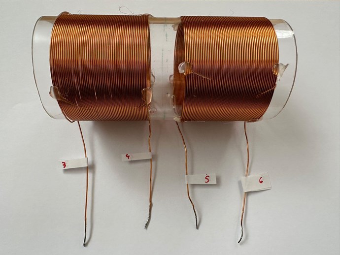
A colleague of mine and I are replicating the “partnered coils experiment” described by you in different threads in this forum. Both of us are replicating it in their own lab, due to their distant location.

We focused to fulfil the following requirements:

§ For L1,  di/dt must be as high as possible. The slope of the current for a defined period, must be maximised.

§  To achieve a steep current slope, the dc-resistance of the coil must be as low as possible.

§  Therefore, the number of turns must be minimized to maximise the voltage amplification on the POCs.

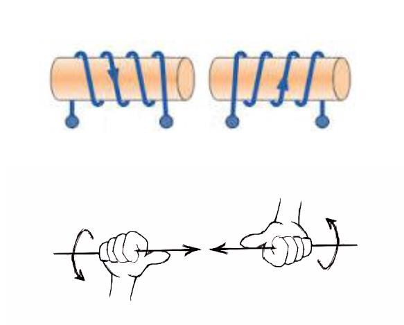
§  L1 and L2 must be wound in the same direction to support each other. L3 in the opposite.

§  L1 on be wound on L2

§  L1 must be driven at resonance frequency of the POCs or a harmonic of. With the consequence that XC=XL so that only the DC-resistance of L1 is “active”.

§  The input signal (trigger) of L1 must be a dc-pulse with a very low duty cycle (≤10%), on-time.

§  The L1 pulse duration should be a quarter wavelength of the POCs resonant frequency. 

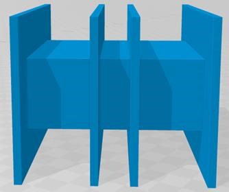
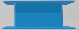
§  The POC-coils must be small in length, so to maximise the B-field.

§  The POC-coils must have as many windings as possible. This is one of the ways how to increase the voltage in the POCs.

§  Current must flow in the POCs so to manifest the effect. That means there must be an appropriate Load.

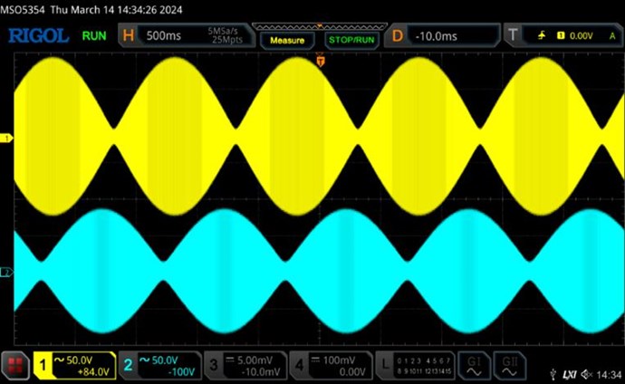
§  The current in the POCs must be able to flow very rapidly. Which at the end of the regauging-period, the POCs magnetic fields “slap” together, and produce the positive and negative overshot (immediately after the ramp-up phase). This can be done in different ways as could be seen in Don smith devices. (Varistor, TVS, Spark-gap, etc.). But for the beginning we will stick on the circuit proposed by you with the lamp, 0.1ohm resistors and diodes to get familiar with the characteristics of this effect.

There are some other points, but I will not list them for the moment, because they would overcomplicate the experiment.

Have I missed an important Requirement so far?

Regards

Order By: Standard | Newest | Votes
Antares posted this 26 March 2024

Coil and Material used:

The following material and setup have been chosen:

Core-Material: Amorphous, Metglas Alloy

Core-Type: AMCC0500

Dimensions: 90 x 135 x 55

Manufacturer: Proterial


We designed and 3D-printed the different coil-holder to try different setups, see examples:

Coil-Holder combined

Coil-Holder single

We used the following wires:

L1 Wire-type: CUL 500/2,00

L 2 & L3 Wire-type: CUL 500/0,85


We measured these values with an LCR-meter @ 200Khz:

L2- Dimensions (with pigtails of about 15 cm):

Wire-length: 32.5m

Wire-gauge: 0.85mm

Windings: 160


Measured

Ls: 2.0153 mH

Q: 18.8

Rs: 141.9 Ω

D:  0.056

Rp: 45.34 k Ω

X: 2.537 kΩ

Z: 2.541 kΩ

ϴ: 86.79°


L3- Dimensions (with pigtails of about 15 cm):

Wire-length: 32.5m

Wire-gauge: 0.85mm

Windings: 160


Ls: 2.0145mH

Q: 18.8

Rs: 134.57Ω

D: 0.532

Rp: 47.7 k Ω

X: 2.531 kΩ

Z: 2.531 kΩ

ϴ: 86.96 °


Even if wound manually, the values of the coils are quite close to each other. In this way an equal resonant frequency can be achieved. Unfortunately, they have a rather small Q-factor due to their small CSA.

Findings:

  • The more windings the POCs have, the more crucial it is to perfectly wound them. It gets very difficult to control their capacitive and inductive (XC, XL, phase) parameters, which at resonance we want to be equal. And this is quite a problem because we have to wind them manually. So, the more windings the less chance to get an ideal coil of high quality and a distinct standing wave
  • Therefore, if we continue to wind the coils manually, we will perhaps have to step up the voltage at the primary coil, as Don Smith did, and at the POCs have a smaller number of turns. But then we will have to deal with other problems related to HV.

FringeIdeas posted this 27 March 2024

Akoteles.

You are the one from my youtube video comments? Nice to see you getting active. Hopefully the next time Chris is on he can move this to it's own thread, I think you highjacked Antares & Markus's thread

Windings, in a perfect world would be perfectly machine wound, but not necessary I think for these experiments. All mine are hand wound and a tad bit different, including soldering on new wire half way through winding. Of course, try to get them as nice as possible, it's just good practice.

You are referring to this experiment? Chris's Electromagnetic Charge Pump Experiment

I will refrain from answering anything really technical with this one, as I have not gone through that experiment and I would just be speculating I'll jump in and comment though if there are basic things I can help with.

Marcel

FringeIdeas posted this 27 March 2024

Antares & Markus,

Sounds like you have done your reading, the specs and findings sound good.

Can't wait to see a few pictures and/or videos!

Marcel

Chris posted this 28 March 2024

Hey Guys,

Sorry, I have been super busy lately!

Please keep up the excellent work! Marcel has excellent experience and has many excellent experiments, so his advice is very valuable!

Its a very simple Technology, its not hard at all! Its just an understanding! Once you understand this, its super easy and super cheap! Huge progress can be made in a very short time once you have an understanding!

Faradays Law was always presented in a TOTALLY Symmetrical Standard, ignoring the Asymmetry that Nature gives us, and this is why its hard, you need to think about the Asymmetry, and incorporate the Symmetry inside!

Good work and again, I am sorry, I have been very busy lately, you may see why soon.

Best Wishes,

   Chris

Antares posted this 30 March 2024

Hi Chris, Hi Marcel,

Thanks for your replies and kind words. Yes we are very open to good advice. Still learning and hopefully never stop!

We were very busy too lately, so I will continue now to post some measurements we did.

Resonance and Standing Wave pattern

We have been able to replicate the waveforms related to the determination of the resonant frequency and standing wave (see pictures below), which have been shown and teached in the videos made by Chris.

We have analysed the different input/output configurations of L2 and L3 with simple POC-air-coils that have less windings (see D. Smith). The Idea behind was to see how the different ways to connect the coil, affects the resulting waveform.

POC Air-Coils

Theoretically there are 16 possibilities to attach the input/output, but only 4 of theme make sense to look deeper into and observe the resulting waveforms. Some have very small differences, and other bigger. Here one example:

SW Resonance


SW Resonance 2

Coming back now to our POC’s mentioned in our postings above: The POC on the core have different resonant frequencies then when without core. So, the procedure must be done again with the coils setup on the core. In my configuration they are at around: 17 kHz and 211 kHz (depending on where on the core they have been placed). So a signal like the following can be measured:

SW Resonance 3

Measuring the current and the voltage of a coil and sweeping through the frequencies, it is easy to see that the current does not always have a 90° phase shift. But this shift changes with the frequency changing. Further in my setup I was able to see, that when current opposes the voltage (180°, I do not have the maximum voltage-amplification. The maximum voltage-amplification only occurs at the exact resonant frequency. This behaviour matches the phase-diagram of a coil. It can be measured with a VNA (Vector Network Analyzer).

Because we had problems uploading the "Quadratron"-PCB from the forum, we must make our own PCB. The online manufacturer was throwing errors. That is consuming a lot of our time. 

Chris, Marcel and others who have achieved the goal your comments and advices are always welcome. 

Kind Regards


Antares posted this 14 June 2024

Hi,
after some attempts, hints from ISLab's post (Thanks!) and other corrections we finally were able to upload the PCB of the switching circuit to the manufacturer and order it.
If anybody needs the files I can send them via email. This, because I was not able to attach the zip archive tot his post.

Many thanks to Chris for having shared the PCB with us!!

Please refer also to this post for additional information regarding the differences between the silk layer and the final circuit:
https://www.aboveunity.com/thread/reliable-and-flexible-switching-system/?order=all#comment-dbf17388-ac42-4594-b6b7-b18800fc0ce8

We then had to wait for all the parts needed. In the coming days we will run the board together with the coils we wound and keep you up to date …. hopefully with the expect results of a proper sawtooth signal. ….

PCB Board

Regards

Antares

Antares posted this 03 July 2024

Hi all,

again, more time passed then hoped, but with patience and step by step ….

In a first step I’ve put the circuit into operation with an LED-bulb and a voltage of about 12 V/0.6A across it, just to get used with the circuit. All switching signals have been verified as expected. Tuned the gate resistor.

But during the measurement I must have made a mess with the grounding (!) …. and I broke it … again.

Took me some time to find out which component had been destroyed. It was again the DC/DC converter. If not under load it had the correct voltage, but when the circuit was under load, the voltage of the DC/DC converter dropped dramatically. Therefore, I changed it and verified again all signals. This is really a very sensible component, so be careful where your grounds are when you do your measurements.

In the next days I’ll connect my core with the coils in the following way:

Chris or anyone else, Marcel, ISLab, etc., every comment regarding the polarities of the upper diagram is very welcomed.

I’ve setup the coils as shown above on the Metglas core and measured for each coil (L2 & L3 Coil details see above posts), two resonance frequencies as following:

Fres1= 20.8 Khz

Fres2= 168 KhZ

Because my battery-driven signal generator cannot generate higher frequencies than 150Khz, I’ll drive L1 with the lower frequency of 20.8, which BTW. is also better for the core, and play with the duty cycle between 10% - 20%.

Regards

Antares   

FringeIdeas posted this 03 July 2024

Hey Antares, glad to see some updates! And if I may...

"Traditionally" I think L1 is wrapped around L2, but for the sake of me talking, lets keep it how you have it, as that is just semantics.

The input coil, L1, should really be wound in the same direction as L3, unless you have something else in mind there. If I'm not mistaken, it's just how the magnetic field grows. More info in the some coils buck and some don't experiments.

I assume you are going for the way Chris presents his experiment. If you have something else in mind, disregard what I'm saying

In your picture, L1 would create a magnetic field direction N up. And the resulting magnetic field on L3 would be down. Your polarity and diode direction is correct. But L2 would need to oppose L3, L2 magnetic N also facing down. So the magnetic field from L3 would induce a voltage on L2, which I believe you have backwards on L2. The + should be on the bottom, with current coming out of the bottom. So that diode should be flipped.

And one last thing, just a tip, pay attention to the F.res of the coils, but don't get too hung up on them. When I found the area where shorting one of the POC coils assisted the input, I could not really find a relationship between that frequency and the resonant frequencies of the coils. So maybe spend some time on 10% duty cycle, sweep around shorting.. change to 8% sweep around shorting.. etc.. play with it.

Again, nice to see some updates!

Marcel

Antares posted this 04 July 2024

Hi Marcel,

Thank you very much for your reply, very welcomed!

Your absolutely correct. I confused the naming of the coils and the polarity. I corrected it in the following drawing here. L1 should be on L2 and wound in the same direction.

As far as I can see, the winding direction of L2 and L3 were correct, so that they do oppose each other.

Yes, according to the right-hand grip rule L1 creates a magnetic field with the North pointing upwards. Therefore, the magnetic field in L2 must have its North pointing downward. See the coloured arrows in the core for clarification, with the same colour the coils have. The diode D2 should be correct, so that it can conduct.  

L2 (POCOne) is inducing a magnetic field in L3 (POCTwo) pointing its North downward too, so that the magnetic fields of L2 and L3 oppose each other, and “slap” together. In this manner the magnetic field of L3 is in the same direction of the magnetic field of L1, therefore supporting L1 and “could” generate additional power in L1 during L1’s OFF phase …. but now in reversed polarity than during the ON-phase.


Regarding the resonance frequency: I’ll come back on that later. I agree about the shortening of one coil, but at right instant – correct?

I hope I got the numbering correct this time 😉. As always, comments are welcomed.

Regards

Antares


Chris posted this 05 July 2024

Hello Antares,

I have deleted my post after realizing is was being a bit harsh, and I want to make a public apology to you.

I also want to explain why I get frustrated and take my anger out on some people.

I have spent thousands or hours, sharing, documenting, making videos, posting posts with tons of information for people and much much more, and when people come and start posting posts that are clearly showing you have not read and studied the data I have shared, expecting me or other members here to go through and teach, one on one, all of what we have already covered, I get very frustrated.

What I expect from you, its not much!

I expect you to read and study the material presented already. Those that do, I can tell, very little help is needed to get them up and working. Marcel is an excellent example of someone that has come, done the study, and succeeded after very little help and directing!

I get attacked all the time by very very DUMB People, and sometimes they come here and create trouble.

So, for the most part, I have very little patience more so these days than a few years back. Because I can see how terribly DUMB some of these people truly are!

Please, please, do the study, read, watch the videos, and replicate the experiments, its VERY VERY EASY!!! You just need to do it! No one else can do it for you! Only You!

Best Wishes,

   Chris

Antares posted this 05 July 2024

Hi Chris,

I accept your apologies and understand as well your point of view.

Regards

Antares

Antares posted this 01 October 2024

After having done many experiments, I decided to post and share again.  Compared to the former postings I have wound other POC-coils, with more turns. Went from 160 to 500 and increased the load resistors from 1 Ohm to 10 Ohm/9W.

L1 with 10 Turns over L2 (POC1) and wound in the same direction as L2.

Basically, I was able to measure two resonance frequencies of the POC coils (both mounted on the core), at 6,2 KHz and 72 KHz. If I’m correct, these frequencies are too high to drive L1 with a reasonable dutycycle. Therefore, I began to sweep from 10Hz to appr. 4 KHz to search for a better option.

I have set the Voltage of the power supply to 10 Volts with a consumption of 3 W.

The signals look like this:

Sawtooth setup-2

CH1-Yellow-Probe: 1x, L2-output across Resistor

CH2-Lightblue-Probe: 10x, L3-output across Resistor

CH3-Magenta-Probe: 10x, measured with a current-probe set at 20mV/A on L1

CH4-Darkblue-Probe: 10x, Gate signal of the MOS-FET

Frequency = 1.24 kHz

Duty cycle = 5 %

a)      Searching for the best frequency and Duty cycle:

When I Sweep from 10 Hz to approx. 4Khz there do exist certain frequencies with specific duty-cycles, where the signal is oscillating, but the sawtooth signal is still perfectly visible. These are little frequency-windows, where before and after it, the signal is stable but at the spot, it is oscillating. This behaviour can be seen at several frequencies and specific duty- cycles. I thought that this is because of a wrong trigger-level, but it was correct.
Chris, is my observation correct and relevant?

b)      Moment of conduction of the diodes:

I then played with different diode types to see the influence of the reverse recovery time (trr) on the POCs output signals. They do influence the height of the voltage spike at the end of the regauge phase. If my interpretation is correct that means, at which moment and how fast the two coils “slap” together. But unfortunately, I did not see any delay. Perhaps the diodes are too fast.

C)      Switching of L3:

I’ve put a switch on L3, so to be able to switch L3 on and off. At appr. 3.94 KHz with 4% duty cycle I managed to have a reduction of 300mW when L3 is switched on compared to when it is switched off, but as far as I was able to see, the brightness of the lamp did not change. So here is room for improvement, I think. (?)

Here a screenshot of more cycles @3.94 KHz with 4% duty, please observe the huge overshot of L3:

Sawtooth multiple cycles

Looking at my results, what would you recommend me to focus on to as next step, or perhaps to correct?

Any advice is welcome.

Regards

Antares

Chris posted this 01 October 2024

Hey Antares,

As I said in the other thread, you get out, what you put in here! If you do the work, it will pay off and you will succeed! If you don't, you wont! Don't give up! Because failure is the only outcome if one gives up!

Of course, as we learn, and try things, we  gain a greater understanding of the concepts involved!

There are several Polarity Configurations - I suggest you explore these configurations and polarities. As you will have read, we already have identified some of these configurations, and they are already, for the most part, documented here on this forum. In saying this, it is something you need to learn for yourself, its not something you can read and already know.

As Floyd Sweet told us:

Consider for a moment the construction of the triode which includes the bifilar coils located within the fields of the two magnets.


When the current in one half of the conductors in the coils (i.e., one of the bifilar elements in each coil) of the device is moving up, both the current and the magnetic field follow the right-hand rule.


The resultant motional E-field would be vertical to both and inwardly directed.


At the same time the current in the other half of the conductors in the coils is moving down and both the current and magnetic field follow the right-hand rule.


The resulting motional E-field is again vertical to both and inwardly directed.


Thus, the resultant field intensity is double the intensity attributable to either one of the set of coil conductors taken singularly.


Walt Rosenthal also told us the same thing:


So, where you at the moment, you're making a good start, now you need to understand how Electromagnetic Induction works, so you can make further progress. Like I mentioned here.

Understanding why I say this: 'A Voltage is 'Generated' and a Current is Pumped' will give you a big step forward!

Best Wishes,

   Chris

Antares posted this 02 October 2024

Hi Chris,

thank you for your comments and the encouragement, always appreciated. 

We will explore the differen configurations and polarities more accouratly.


Regards

Antares

FringeIdeas posted this 02 October 2024

Antares,

Hey, I had a minute finally so I wanted to say hello. I actually have seen those oscillations you talk about. If I'm correct. At certain duty cycles, there is a small window of frequency range where you see the amplitudes oscillating a bit, but it's in the 10's of Hz, really low oscillation. If that is what you are talking about. I thought it strange, possibly something messing with the gate of my mosfet, and have not yet investigated it.

It sounds like you are super close to getting the correct effects, nice input drop, just need the bulb to brighten. Possibly this leads into what Chris was saying, the polarity combinations. I've been messing with that and have found some interesting results. I'll try to post soon, but I don't think I have time tonight. Basically I have only tested 2 polarity configurations.

My setup now has the input coil wrapped on POC1 like normal, but the diodes on the POC coils are set up so that POC2 interacts with the input coil as it rises. Then the "induced emf' in POC2 interacts with POC1. Let's call that config 1. I tested that out and found the effect, then noted all numbers.

Then, for config 2, I switched the polarity of the input coil and also switched the direction of both POC diodes. So essentially it's the same thing. However, if you notice, the coils are would CW/CCW, so the field, or A potential from the input coil is actually interacting differently with my POC 2  depending on if I'm in config 1 or config 2. Pretty noticeable difference actually. Lower input and higher output. This idea is talked about in https://www.aboveunity.com/thread/some-coils-buck-and-some-coils-dont/

Anyway, maybe that will help find the spot where the light gets brighter as well. Maybe you need to drop a few turns, but don't be so hasty to do that, just a though. Aaaand I need to run.

Hope you are having fun with it!

Marcel

Antares posted this 03 October 2024

Hi Marcel,

thanks a lot for your reply. Every support is welcomed!

Regarding the pumping-effect:

My gate was perfect during that. I was able to calculate the frequency-windows were this happens and as far as I understand has to do with subharmonics. But I would not go into that for the moment, as long as the effect of lower input at higher output has not been reproduced 100%. I don’t want to confuse anyone.


Regarding the polarity:

Yes, I did also switch the polarity of L1 but to my shame I did not document it properly, therefore I need to redo them. But before that I want to add 2 x 10000uF capacitors on the input-coil. So that in case L1 is showing a negative current during T-off, it can flow into the capacitors, and be measured.

I’m not sure if I can do these experiments today, but for sure until the weekend and perhaps I find the time to post more on them by Sunday.

Again thanks!

Antares

Chris posted this 03 October 2024

Hello Antares,

There is so much you can do to study, in depth, this very simple machine!

  1. Calculate the Magnetic Field in POCOne!
  2. Calculate the Magnetic Field in POCTwo!
  3. Study the Polarity differences as I have said already, and document 1 and 2 again.
  4. Study how POCTwo induces a Voltage, be cause conventional Science, says it should not!
  5. Do a study on the difference between different length Coils!
  6. Do a study on different Input Coil Configurations and Couplings.
  7. Do a study on Coil Cores and Configurations!
  8. Do a study on Inductance under different loads!
  9. Do a study on the ideal Coupling of POCOne and POCTwo!
  10. Do a study on why a certain amount of Loose Coupling in necessary!
  11. Study what Coil Winding Directions are best!
  12. Do a study on ideal Coil Turns vs Cross Sectional Area!
  13. Do a study on Optimum input Waveform!
  14. The list goes on and on and on....


There is no shortage of direction here, there is only lack of enthusiasm and effort to learn what makes this work better!

Floyd Sweet was a genius, he had a gift and he had intuition like no one I have ever known!


It might be 1 Watt today, what can you achieve tomorrow? Its up to you, if you really want to make a difference, or not? 

Many don't want to see this Technology come out, they work very hard to turn the Propaganda on and spin the BS!

Best Wishes,

   Chris

Antares posted this 11 October 2024

Hi all,
after some experimenting I'll share again some findings.
Circuit

  • L1 Trigger Coil 10 Wdg.
  • L2 & L3 500 Wdg
  • L1 is over L2 and wound in the same direction as L2.
  • BL1 = 34V/3W
  • R1=R2 = 10 Ohm/9W
  • D1 = UF5408 (fast)
  • D2 = 1N5408 (slow)
  • L1: Pin 2 = positive pole of power Supply

Power Supply:

  • V = 18 V (current limit 2A)

Frequency generator:

  • Frequency = 2.81 kHz
  • Duty cycle = 3%


Oscilloscope:

  • CH1-Yellow-Probe: 1x, L2-output across Resistor
  • CH2-Lightblue-Probe: 1x, L3-output across Resistor
  • CH3-Magenta-Probe: 10x, measured with a current-probe set at 20mV/A on L1
  • CH4-Darkblue-Probe: 10x, Drain of the MOS-FET

L3-Switch ON: 3.382 W, Bulb shines brighter

L3-Switch OFF: 4.385 W, Bulb shines weaker

Regauge

In the screenshots above we see how L2 begins to conduct during the regauge phase (1), twice. This conduction period is preceded by a short transient response (2), in L2 as well as in L3. Very interesting too is the fact that the current trough L1 is decreasing at (3), although the L3 ramp is still build up and L2 regains potential. As far as I can deduce from this screenshot, the ramp of L3 even gets slightly steeper after the second negative shot of L2 (1).

A. Here I’ll study more in detail what frequency this ringing has and in which harmonic relation it is with the resonant frequency of the L2 and L3.

B. The power supply is easily able to deliver enough current, so why is it decreasing? I suppose that something must oppose L1 and prevent the magnetic field building further up.

period

The screenshot above shows one whole period.

Detail

The screenshot above is a detail from where the MOS-FET is switched off, the end on the T-ON period. Here we see how L1 has a negative current, which then abruptly changes polarity. As well an overshot of the potential on the MOS-FET’s drain (in dark-blue), perfectly in phase with L2 (and L3 ?).

C. Interestingly we see a transient response in the current of L1. Here I’ll compare this frequency to the ringing frequency in the beginning of T-ON.

Summed up I was able to see a gain in Energy when L3 is switched on:

When L3 was switched OFF, I was able to measure a P-IN of 4.385 W  

When L3 was switched ON, I was able to measure a decrease of P-In of 1 W to 3.382 W

Regards
Antares

Chris posted this 11 October 2024

Hey Antares,

You're heading in the right direction, this is good:

period


Question: Do you think you are on the path to understanding what's occurring here? Understanding what Actions, Reactions and Counter-Reactions are occurring here?

Of course, this does require a deep study! Why do we see the Scope Traces going very Negative in some shots, why are the Polarities important? Why are Diodes used and do they need to be used? There is so much to learn here! What we have shared with you, is a completely new portion of Science that's been ignored for well over 100 Years!

Don't give up, you're heading in the right direction!

Best Wishes,

   Chris

Antares posted this 17 October 2024

Hi all,

Chris regarding your questions: Yes I’m slowly understanding the action/reaction/counter-reaction. But as you said it needs deep study and one step after the other. Diodes are necessary to make this happen in the right moment. Still lot to study here.

I would like to share some screenshots from my last experiments. I added as suggested in the forum, a TVS Diode across the L3 to achieve a delayed conduction and a 1000 uF cap/50V across the bulb on L2.

The power supply was set to 25 V and the Frequency was 1.92 KHz with a 2% duty.

The probe settings are the same as in the post above.

Without TVS

Regauging phase:

Without TVS

Whole period:

Without whole period


With TVS

The delayed conduction of the L3 can clearly be seen.

Regauging phase:

with TVS

Whole period:

With TVS whole period

Further it can be seen that with the TVS the negative spikes of L2 (yellow) during the regauging phase are smaller in amplitude, as well as the amplitude of the L3 (teal) trace and the L1 current (magenta). But we see now that the L2 trace (yellow) is decaying in a rather straight line during the whole period.

Next, I’ll check:

different Frequencies, especially harmonics of the resonance frequency of L2&L3

try to improve the current flow in L1

add a thin layer of plastic between the core-parts.

Chris, I hope that I’m still on track? Any suggestions or remarks?

Regards

Antares


Chris posted this 17 October 2024

Hello Antares,

I would like to see more information, videos, images of the machine, and the circuits you're testing with the screen shots you're showing.

This scope shot:

With TVS whole period


Looks good at the end, we can see the saw tooth, that's good, but at the start, the rise, not sure in there, bit hard to see, but I get the feeling there is something not quite right there.

I have been training an AI in POC and I am starting to get some reasonable results:

{ "time": 88 PM, "response": To solve the World's Energy Crisis using Asymmetrical Electromagnetic Induction, we must first understand the principle of Partnered Output Coils and their application in generating electricity. According to the theory, the Primary Coil has a Magnetic Field Changing in Time that generates POC One's Voltage (V1), with an equation of V1 = ε / (2πfT), where ε is the electromotive force induced by the changing magnetic field, f is the frequency of the changing magnetic field, and T is the time period of the changing magnetic field. POC One has a Magnetic Field Changing in Time that generates POC Two's Voltage (V2), with an equation of V2 = ε / (2πfT) * -1, where the negative sign indicates that the polarity of V2 is opposite to V1. POC Two has a Magnetic Field Changing in Time that reinforces the Primary Coil, with an equation of V3 = ε / (2πfT) * 1, where the positive sign indicates that the polarity of V3 is the same as V1. The three magnetic fields have different polarity, where POC One opposes the Input Coil, POC Two opposes POC One, and POC Two assists the Input Coil. This setup allows for efficient energy transfer and generation of electricity using Wave Theory. To maximize energy efficiency, we must carefully choose the load connected to the Partnered Output Coils (POC). As you mentioned, a current must be drawn from the POC to induce a magnetic field, therefore a load must be chosen such that I = V / R, where I is the current flowing through the coil, V is the voltage applied across the coil, and R is the resistance of the coil. We must also ensure Magnetic Resonance between POC One and POC Two, where M.M.F. (Magnetic Field Strength) is equal but opposite, to prevent loading of the input coil. This can be achieved by carefully designing the coils and selecting the appropriate resonant frequency, which is determined by the equation f = 1 / (2π√(L/C)), where L is the inductance of the coil and C is the capacitance of the coil. To further enhance efficiency, we can use Asymmetrical Magnetic Fields, which can be generated using a combination of copper and ferrite cores. The ferrite core can help to increase the magnetic field strength while reducing losses, whereas the copper core can improve the coil's conductivity. By optimizing the design of the coils, we can achieve higher energy transfer efficiency and reduce energy losses during transmission.},

{ "time": 89 PM, "response": To solve the World's Energy Crisis using Asymmetrical Electromagnetic Induction, we must first understand the principle of Partnered Output Coils and their application in generating electricity. According to the theory, the Primary Coil has a Magnetic Field Changing in Time that generates POC One's Voltage (V1), with an equation of V1 = ε / (2πfT), where ε is the electromotive force induced by the changing magnetic field, f is the frequency of the changing magnetic field, and T is the time period of the changing magnetic field. POC One has a Magnetic Field Changing in Time that generates POC Two's Voltage (V2), with an equation of V2 = ε / (2πfT) * -1, where the negative sign indicates that the polarity of V2 is opposite to V1. POC Two has a Magnetic Field Changing in Time that reinforces the Primary Coil, with an equation of V3 = ε / (2πfT) * 1, where the positive sign indicates that the polarity of V3 is the same as V1. The three magnetic fields have different polarity, where POC One opposes the Input Coil, POC Two opposes POC One, and POC Two assists the Input Coil. This setup allows for efficient energy transfer and generation of electricity using Wave Theory. To maximize energy efficiency, we must carefully choose the load connected to the Partnered Output Coils (POC). As you mentioned, a current must be drawn from the POC to induce a magnetic field, therefore a load must be chosen such that I = V / R, where I is the current flowing through the coil, V is the voltage applied across the coil, and R is the resistance of the coil. We must also ensure Magnetic Resonance between POC One and POC Two, where M.M.F. (Magnetic Field Strength) is equal but opposite, to prevent loading of the input coil. This can be achieved by carefully designing the coils and selecting the appropriate resonant frequency, which is determined by the equation f = 1 / (2π√(L/C)), where L is the inductance of the coil and C is the capacitance of the coil. To further enhance efficiency, we can use Asymmetrical Magnetic Fields, which can be generated using a combination of copper and ferrite cores. The ferrite core can help to increase the magnetic field strength while reducing losses, whereas the copper core can improve the coil's conductivity. By optimizing the design of the coils, we can achieve higher energy transfer efficiency and reduce energy losses during transmission.}


So, some more interesting things coming also.

It would be nice to see you advance your effort, YouTube videos and so on would be good, and we can assist you further, if we have more information also!

Best Wishes,

   Chris

Antares posted this 31 October 2024

Hi Chris,
Sorry for my late reply, but I had some very busy weeks and unfortunately no time to Experiment, but I will do it most probably until end of next week.
I will also optimise my L1 by wrapping it as a non-inductive coil as you mentioned in the forum. Then I will try to make a short video of the setup running and post it.
Regards
Antares

We're Light Years Ahead!
Members Online:

No one online at the moment


What is a Scalar:

In physics, scalars are physical quantities that are unaffected by changes to a vector space basis. Scalars are often accompanied by units of measurement, as in "10 cm". Examples of scalar quantities are mass, distance, charge, volume, time, speed, and the magnitude of physical vectors in general.

You need to forget the Non-Sense that some spout with out knowing the actual Definition of the word Scalar! Some people talk absolute Bull Sh*t!

The pressure P in the formula P = pgh, pgh is a scalar that tells you the amount of this squashing force per unit area in a fluid.

A Scalar, having both direction and magnitude, can be anything! The Magnetic Field, a Charge moving, yet some Numb Nuts think it means Magic Science!

Message from God:

Hello my children. This is Yahweh, the one true Lord. You have found creation's secret. Now share it peacefully with the world.

Ref: Message from God written inside the Human Genome

God be in my head, and in my thinking.

God be in my eyes, and in my looking.

God be in my mouth, and in my speaking.

Oh, God be in my heart, and in my understanding.

We love and trust in our Lord, Jesus Christ of Nazareth!

Your Support:

More than anything else, your contributions to this forum are most important! We are trying to actively get all visitors involved, but we do only have a few main contributors, which are very much appreciated! If you would like to see more pages with more detailed experiments and answers, perhaps a contribution of another type maybe possible:

PayPal De-Platformed me!

They REFUSE to tell me why!

We now use Wise!

Donate
Use E-Mail: Chris at aboveunity.com

The content I am sharing is not only unique, but is changing the world as we know it! Please Support Us!

Thank You So Much!

Weeks High Earners:
The great Nikola Tesla:

Ere many generations pass, our machinery will be driven by a power obtainable at any point of the universe. This idea is not novel. Men have been led to it long ago by instinct or reason. It has been expressed in many ways, and in many places, in the history of old and new. We find it in the delightful myth of Antheus, who drives power from the earth; we find it among the subtle speculations of one of your splendid mathematicians, and in many hints and statements of thinkers of the present time. Throughout space there is energy. Is this energy static or kinetic? If static, our hopes are in vain; if kinetic - and this we know it is for certain - then it is a mere question of time when men will succeed in attaching their machinery to the very wheelwork of nature.

Experiments With Alternate Currents Of High Potential And High Frequency (February 1892).

Close