Hey Jenkorun,
Glad to hear you have given the AI QnA Bot a go, and yes, some questions, even if its along the lines of the Topic of this site, may sometimes be incoherent to some degree. AI is getting much better, but its still got a way to go.
In saying this, I am still working on this and am trying to make it more accurate and have better board spectrum context. In time, it will get better! For new comers, asking basic questions, that are not too advanced, and having a Context with the data in relation to the question, it generally is pretty accurate and does generally give very good answers. You could try asking questions a few different ways, this can give better answers, as key words will appear in different parts of the Context. Also, as time goes on, and the speed of the AI improves, I will broaden the Context to cover more topics. This will help immensely!
Regarding your Questions:
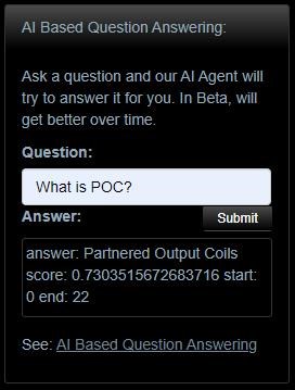
can someone direct me to the sticky thread that specifically covers the principles and basics of the automatic impedance matching the POC shows please? At least I assume that's what it does.
Both Questions are linked, so the answer to both will be provided below.
I'm looking for information on how to prevent the load from detuning the system when attached or switching loads, is it something like this video or something else?
This is another fantastic question!
Short Answer:
By stopping the change of Impedance under System Load.
Long Answer:
To answer this question, we need to first understand why Loading a System, changes the way a System behaves. Say we have a series of Ten Ohm Resistors, and each resistor is on a switch, a Transformer supplies 12 Volts to the Circuit and we have all of the Resistors in Parallel Switched Circuit, like so:
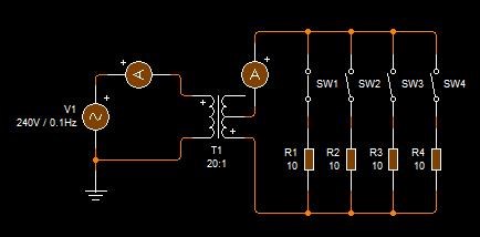
We know, from EE Class, that the equation for Resistors in Parallel, follows the following notation:
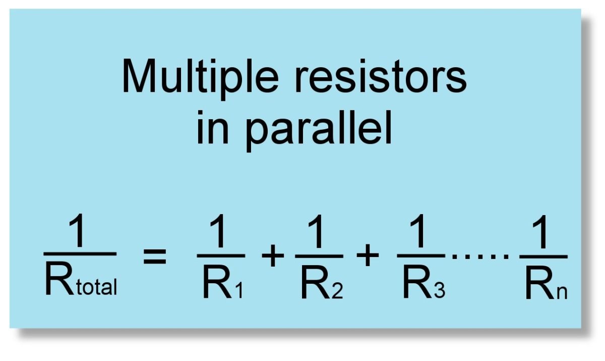
If we do some quick math:
- 1 / RTotal = 1/10 + 1/10 + 1/10 + 1/10 = 2.5 Ohms Total
- 1 / RTotal = 1/10 + 1/10 + 1/10 = 3.3 Ohms
- 1 / RTotal = 1/10 + 1/10 = 5 Ohms
So, in this situation, we get a lower Resistance than the single Resistor R, as the Load increases, the Current to the Load increases, because the Resistance of the load Decreases, but this is not the full story! There is more!
The Impedance of the Coils also decrease!
As the External Load increases, the Impedance of the Coils Decrease, making the Coils inside this Symmetrical, Conventional Transformer, capable of carrying more Current, thus, the Input of the Transformer will see the same, linear increase in Current, on the input, until we reach Saturation, and then the Input Current becomes Non-Linear.
So, the Magnetic Field itself, changing, under load, changes the Impedance of the Coils, allowing change of Current inside the Coils on both the Input and Output, thus the Inductance of the Coils, because Inductance is the measure of Current Flow in the Coils, remember? also changes! A Conventional Transformer does have a Non-Linear Inductance change, this is seen when a Transformer Saturates, and sometimes can catch fire, because the Transformer has lost all of its Inductance:
So, how do we stop this occurring? How do we isolate the explained Changes? How do we use Coils to isolate the Input from the Output?
Superposition:
Superposition theorem states that in any linear, bilateral network where more than one source is present, the response across any element in the circuit is the sum of the responses obtained from each source considered separately. In contrast, all other sources are replaced by their internal resistance.
Ref: Superposition Theorem
If our Input Coil is exposed to an output Coil that is always opposed to the Change, Lenz's Law, then the Superposition Theorem says, we get a total MMF Vector Equation of: M.M.FPrimary + M.M.FSecondary = Zero!
And now, to answer your question: We need to change the way the Transformer works! We need to Introduce Asymmetry to a strictly Symmetrical discipline, and we need to use Superposition to change the equation seen above, from:
M.M.FPrimary + M.M.FSecondary = Zero
to:
M.M.FPrimary + M.M.FSecondary + M.M.FTertiary = M.M.FTertiary
I have shown everyone how to do this already, this is already fully explained technology, here on this forum!
When you have M.M.FSecondary ≅ M.M.FTertiary, you have reached Magnetic Resonance! Thus, at Magnetic Resonance, your Input Coil is completely isolated from your Output Coils, because the Magnetic Field Vector, back on your Input Coil, cancel out, your Input Coil see's just as much Positive Force as it does Negative Force: 1 + -1 = 0 effect back on your Input! In real world application, this is not entirely accurate, your Input Coil can see Negative Power coming back, more than the Positive Power going in, so be aware of this.
In achieving this very easy task, you have the ability to have huge gains, because we have a fully open System, the system we have built, for a few dollars, now can extract as much Energy as one can from the specified Design and Geometry, as one wishes, with very little impact, negatively, on the Input!
If you read my pages, all of this is already fully explained!
Best Wishes,
Chris