Drasko's Asymmetrical Transformer Replication

  • 744 Views
  • Last Post 25 March 2025
Drasko posted this 29 January 2025

Good Day to all,


New to this forum.

This is my attempt at building and replicating the asymmetrical transformer.

I have read many threads on this forum and am new to this technology, just trying to understand it and study it further.

The core is a 1"x1" CSA, 6"x6" L x W. Metglas. The Core has a gap of 4 folded pieces of Kapton Tape.

Below is a picture of the way the machine is currently built.

I have done my best to show winding and diode directions.

The primary coil is drawn separate from the core but is meant to be wound over-top of POCone.

There is a 52W 130v incandescent bulb in parallel with the led and capacitor. (The Capacitor and LED added to POCone output is just an extra load.)


I ask the experienced members to look over this and point out any errors I may have made or if this is correct the way it is.

Blue Print

Physical Build


This is the Scope Shot.

32v 300ma input from power supply.

2.3khz at 0.7% Duty Cycle

Resistors are 0.2ohm 3W


Purple trace is across the resistor for POCone(L2)

Yellow trace is across the resistor for POCtwo(L3)

Scope Shot


https://www.youtube.com/shorts/48z9JMB7os0


Questions:

Is this the Asymmetrical re-gauging ?

Observing the waveform shows me that the SLAPPING of the 2 coils occurs after POCone shows a reverse current, Is this correct?


Thank you all for taking the time and discussing this technology on this forum.

Look forward to continuing this research and helping others along the way.


Drasko.


Order By: Standard | Newest | Votes
Chris posted this 30 January 2025

Hey Drasko,

Very nice! Thank You for sharing your progress!

Of course, everyone knows, the goal here, is to observe a Gain in Voltage and Current at time t, using a smart arrangement of Coils, Asymmetrically arranged. You have achieved this from what I can see, Well Done!

POCOne and POCTwo need to be in Magnetic Resonance, which means Equal but Opposite, Currents 180 Degrees out of Phase, Voltages also, approximately equal in magnitude, so yes, you have this right. This is the basis of Electromagnetic Induction, Lenz's Law is 180 Degrees out of Phase.

The trick is to get the voltage up, and as the Voltage goes up, we pump more Current, because: I = V / R

I will be sharing more soon, showing how to get the Voltage Up in these machines, because this is very important, as we have studied in the Common Mode Choke, Here: Timing, we see the Un-Generation of Voltages, because the Common Mode Choke is designed to use Electromagnetic Induction to remove Transients, or unwanted Voltages, using a Core, Coils arranged in a similar fashion to what we are working on currently.

FYI: See the Timing Thread.

Your waveforms are correct, you have done a really good job here! Thank You for Sharing your Work!

Best Wishes,

   Chris

FringeIdeas posted this 01 February 2025

Hey Drasko, nice. If I may comment a little.

Just a quick nitpick first 🙂 I believe your positive and negative signs on the POC1 and POC2 are backwards. These are induced voltages/currents. So the current would come out of the + terminal. The coil in this state is acting as a battery would, an active element. Vs. the input coil where we are feeding the coil so the coil is in a passive element state, so the + is where the current goes in (which you do have correct in your drawing). But not a big deal, your diodes and magnetic fields look just fine, so it looks like you get it.

But I also wanted to say, spend some time on this. While you are poking around with it, short and un-short POC2, different frequencies and duty cycles, and watch to see if the input current drops, as well as the bulb on POC1 should get a bit brighter. This is evidence that one of the POC coils is assisting the primary. This is also the point where you will possibly see the cop start to peek >1. This is also the point where I've seen a few people just throw their hands up and say there is nothing there. Sometimes it's difficult to locate, but keep at it and you will definitely find it.

As Chris always says, shorter coil lengths and bigger cross sectional areas are better. And play around with different polarities, meaning try switching the direction of the input and go through all the steps of shorting and un-shorting again. Just make sure POC1 and POC2 always oppose each other like you have them now.

And a special ask if I may.. if we are lucky enough to get more scope shots, is it possible to include the input?

And sorry, I meant to comment when you first posted, but it's been hell trying to find any spare time in life lately. Again, awesome job, nice to see the activity and experiments!

Marcel

Drasko posted this 01 February 2025

Hey Chris and Marcel,


Thank you guys for the kind words and guidance,


Chris:

Thank you for maintaining this forum and sharing the information on all these threads, PURE GOLD.

I'm happy to be a part of the forum and show others that it is possible to replicate these experiments, it just takes some effort on the bench and LOTS of reading and re-reading of the forum threads. But eventually light bulbs turn on and things slowly start coming together. Failures occur, Mosfet's blow up, diodes short, you hit a brick wall at times,etc etc. But eventually you start grasping whats happening and what needs to be done to achieve the effects required. I'm still learning and constantly reading and re-reading many threads and letting the information sink in while experimenting with it on the bench back and forth.

Regarding Timing:

If I understand correctly from reading the Timing thread the sequence of events that need to occur are:

  1. Primary Coil is pulsed with a certain Frequency + Duty Cycle + Amplitude, At this time the 2 POC coils are NOT a part of the circuit, meaning not shorted and not loaded in any way just sitting there OPEN circuit, while the primary coil ramps all the way to peak voltage.
  2. Once the Voltage is at peak and the Mosfet for the primary coil is turned off THEN the 2 POC coils are switched on and made a part of the circuit. Meaning POCone has the load connected to it as POCtwo is shorted via a diode to support POCone.
  3. Once the POC coils reach zero current flow, Un-short POCone and POCtwo, Making them an OPEN circuit once again.
  4. Repeat step 1.

My current understanding of what we are doing is creating a magnetic field around the core using the primary coil while the 2 POC coils sit open circuit. Once the magnetic field is at peak around the core we remove the primary coil from the circuit and introduce the 2 POC coils and they now have a collapsing magnetic field that is returning to equilibrium around them and we use that to do work.


Please correct me if I am wrong in any understanding of this.

My next step will be to replace each diode on the 2 POC coils with SCR's(Thyristors). Create a timing circuit that follows the sequence of events from above. Any guidance is appreciated. Will I run into any issues with using SCR's? My assumption is they will continue to conduct on each coil until that coil reaches zero current and then they will naturally stop conducting at that point. I will be using isolation transformers to pulse the SCRs with a quick pulse after primary coil Mosfet is turned off.


Marcel:

Thank you for the Recommendations,


Your not nitpicking😆 its important to point these little details out so others can be on the same page as we discuss this technology. I drew the polarities the way I did to just follow the RIGHT hand grip rule for the coils. It made sense to me this way, I'm just sharing my lab notes I'm sure there's many little things I missed, I'm sure down the road as i understand and grasp this more i will come back to these notes and see all the things i missed.

I have been experimenting with Shorting/Un-Shorting POCtwo and have found some points where the input current is not affected, but I have not yet found a point where the current drops. I will keep experimenting and trying to find that exact spot where the input goes down as the light gets brighter while POCtwo is shorted.

I will attempt the reversed polarity of the primary coil and keep the POC coils the way they are and see the results.

I have a 2 Channel Oscilloscope so I can only show 2 Waveforms at a time. Would you like the Primary coil shown with POCone or POCtwo .


No need to apologize in any way, we all know how life can be at times.


Thanks,

Drasko.

Chris posted this 01 February 2025

Hey Drasko,

My Friend, the key word there: "the sequence of events", you hit the nail on the head!

The Voltage Gained on the Partnered Output Coils is the Critical part to this puzzle! The higher the Voltage gained, the more Current is Pumped, because: I = V / R as we discussed. So the point here is to have a Control Mechanism, to get the Voltage to X Voltage, and then let the Partnered Output Coils do all the work for us.

Because the Output Current is in no way, linked to the Input Coil, it is Isolated, due to Superposition, to a degree. In other words, the Output Coils cancel any Reverse effects, back on the Input Coil, because: 1 + -1 = 0, net zero.

The Voltage Gained on the Partnered Output Coils can be achieved in a few different ways, of course, I decided to start with what I considered to be the safest way first, to keep people safe, the Slapping Together of the Partnered Output Coils at Magnetic Resonance. There are other ways, one of which I alluded to in a few different places, some of them being:

  • Tinman's Mosfet Switch - A Voltage Switch.
  • TVS - Transient Voltage Suppressor.
  • Triac - Light Dimming Circuit with a heavy duty Triac.


There are more that this, this is just some of what I have shared with the community. The Delayed Conduction Thread has been a confusing thread and maybe I have not been clear in some areas, I do try my best to be precise and accurate, but this thread alluded to this switching in at a Voltage X of the Bucking. Again, please remember, I have tried to allude to many ways of doing this but focused on the safest method first, for everyone's safety.

Again, the Goal is to get the Partnered Output Coils Voltage up to a satisfactory number, controlled, and then switch in the Bucking, because at the point of Bucking, the Coils can no longer Generate and Voltage, but they then start Pumping Current. This is a tit for tat, and we have to understand these processes first, to be able to then make advancements.

Safety first everyone, please.

Some of you will have read the story of me blowing about one and a half Centimeters if number 18 AWG out? It was completely gone. Well this is when I saw how dangerous this can be, and that some people need to learn the basics first, to be able to get the bench experience to keep these machines within a realm of Control for Safety.

I want to Thank You Guys and Gals, its so awesome, having good people that want to learn one of the most important subjects that Humanity will ever learn, this technology can Free Humanity completely! You here are spear heading this revolution! Thank You!

Best Wishes,

   Chris

Drasko posted this 01 February 2025

Update:

Below is the Circuit I built for controlling the Primary Mosfet gate triggering (Yellow Trace) and the POCone + POCtwo SCR gate triggering(Purple Trace).

SCR Trigger

As soon as the Primary Mosfet turns off the POC Shorting SCR's turn on.

even if the duty cycle is adjusted the SCR's will not turn on until the mosfet turns off.

60% Duty cycle

Is this the correct way of doing the timing ?

Thanks,

Drasko.


Chris posted this 02 February 2025

Hey Drasko,

If POCOne and POCTwo oppose when you apply the Right Hand Grip Rule and Conventional Current, then you have it right.

POCOne has a Negative M.M.F and POCTwo has a Positive M.M.F, which has a Net M.M.F = Zero.

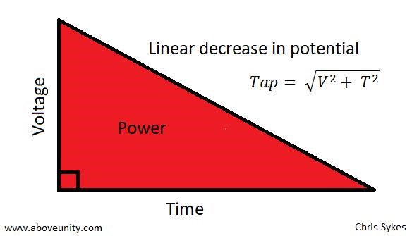
The Sawtooth Waveform is the Triangle: 

Ref: Parallel Wire or Bifilar Coil Experiment


The Voltage and the Current are in phase at time t, which is pure Power! Power Factor = 1.0

Best Wishes,

   Chris

FringeIdeas posted this 02 February 2025

Hey Drasko,

The scope shot request, yes input and POC1 would be fine really. I'm just interested, it's not totally important, thanks!

And while not trying to downgrade what Chris said about switching in at a specific voltage, or step on his toes any, I do want to mention that it is possible to get the effects without using a MOV, SCR, TVS, etc. The effect of manually shorting POC2 and seeing the input go down and the light on POC1 get brighter, should be possible with the basic setup as Chris shows, just diodes in the right polarity and a lamp on POC1.

Of course please experiment with the SCR, etc, as these types of components are used quite often in these machines it seems. I just wanted to mention that effects can be achieved without. It's something I will get back to at some point myself.

Marcel

Chris posted this 02 February 2025

Hey Guys,

Absolutely correct:


I do want to mention that it is possible to get the effects without using a MOV, SCR, TVS, etc.


Yes, there are many ways to make this work, it does work with just Diodes and POCTwo Shorted. We have seen this, on this thread already. To get the voltages up, we need to have an open mind and look at why it is difficult to get the voltages up in Machines that use Bucking Coils.

Best Wishes,

   Chris

Drasko posted this 11 February 2025

Hey Guys,


Below are all the scope shots,

Same running conditions as original post:

32v 300ma input from power supply.

2.3khz at 0.7% Duty Cycle

Resistors are 0.2ohm 3W (All scope shots are across these resistors)

Each section has 2 Scope shots which are the same just the second shot is expanded or zoomed in view.


Primary and POCone

Yellow is Primary

Purple is POCone

Primary and POCone 1of2

Primary and POCone 2of2


Primary and POCtwo

Yellow is Primary

Purple is POCtwo

Primary and POCtwo 1of2

Primary and POCtwo 2of2


POCone and POCtwo

Yellow is POCone

Purple is POCtwo

POCone and POC2 1of2

POCone and POC2 2of2


Thanks,

Drasko.


Drasko posted this 22 March 2025

Hey Guys,

Hope all is well.

Quick Build Update.

AMC1000 Core, Half of core is taped with red electric tape and the other half with black. The parts where the 2 core half's meet is also tapped over with electric tape and insulated creating a small gap when the 2 core half's are put together.

2 Partnered output coils, one is wound clockwise while the other is wound counter clockwise. One is red and the other is black. The bobbins are made from plexi-glass cut out on a cnc router and then glued with super glue.

The Primary coil is wound around  the outside of the whole core and can be made to slide up and down.

Primary Coil - 2 parallel runs of #10Awg, 4.25 turns

Red Coil #10Awg - 15 turns per layer, 3 layers, 45 turns total. Clock wise wound.

Black Coil #10Awg - 15 turns per layer, 3 layers, 45 turns total. Counter-Clockwise wound.

AMC1000 core 1


AMC1000 core 2


AMC1000 core 3


Will update when I have more.


Thanks,

Drasko.

Chris posted this 22 March 2025

Hey Drasko,

Nice build! Thanks for sharing!

This will work really well! Nice sharp, Cap Discharge, sharp, narrow, with the correct polarity on the Diodes, this will spring into live beautify!

Follow the Ideas in Nikola Tesla's Spark Gap Discharges and you'll go a long way!

Don't forget, always load your machine! Always have a Cap for smoothing and Collection!

Best Wishes

   Chris

Adam posted this 25 March 2025

Hello,

Very nice build, looks just like the one I made earlier.

I did not notice any change moving the Primary up or down the core, Please let us know if you have different results on that.


How are you planning on charging the primary discharge cap?


You may want to look at my last post on my thread for some ideas….

Adam’s Experiments and Understanding of coils and magnetism.

Charge cap in series with a small coil and then discharge cap to primary coil in Parallel !

It’s nice to see someone finally working on this setup.

A few things to keep in mind from my own experiments.

When you discharge the cap into the primary coil and the POC coils buck, the cap will recharge to about 75% in reverse polarity. That will be one resonance because it will then want to discharge immediately back to the primary in the revers polarity Back and forth. Depending on your diode placement.

Now if you are charging the cap in series with another small coil to build up the voltage.

Now this is the part I think most don’t see:

Then the series resonant circuit building up must be in sync with the primary discharge circuit or so to say the two resonant circuits must be in resonance with each other.

Two resonant circuits resonating at the exact same time!

Otherwise they will hit each other trying to charge the same cap in reverse polarity at some point costing lots of input energy.

I hope this is not confusing and helps.

Adam.


Chris posted this 25 March 2025

My Friends,

Adam is correct. I posted the link, Adam, I hope you don't mind, to your thread.

Its a real shame, a majority of the Population does not want to know the truth, they are blind to Truth, even though some say Humanity is waking up, well, its evident, majority are still very asleep!

Floyd Sweet gave us the following image:


The following text preceded the above image:

It would appear that a magnetic field is an electric field observed from a motional reference frame. Similarly, if we take a mass with a gravity field around it and we move the mass and create a mass current, a new field is also created. It is a different kind of gravity field with no source and no sink. It is called the Protational field also known as the "Lense-Thirring Effect". This field an its governing principles will  form the basis for future anti-gravity devices.


Conventional Science has other similar concepts:

But the basis, the Rise up, then the Decay Down, follows the Action Reaction Concept! Or, what goes Up must come Down! Some tie this to the Flyback Transformer, but this is only half of the picture.

There are lots of ways to get your Partnered Output Coils to work together, the 1/4 wave concept is one we have explored, where your POC have 4 times the turns as your input coil and trigger on the 4th harmonic.

Those that still think in terms of "Bypassing Lenz's Law", what we have been showing for over a decade now, works as you would expect, by "Bypassing Lenz's Law", however, this is not the right way to think about this technology, its simply Asymmetry of Electromagnetic Induction!

Free Energy Machines are very easy and those still searching are very dumb, we have given the world everything, shown working machines and given the theory freely, and those out there cant see the trees for the forest!

The setup I shared a while back:


Is worth exploring! Its Valuable! Alas, so many guru's will never ever make the effort, but will mouth off, spouting out complete nonsense that is baseless and non-sensical, because that's all they know! We call them: "Blow-Hards"

Enjoy your successes My Friends!

Best Wishes,

   Chris

We're Light Years Ahead!
Members Online:

No one online at the moment


What is a Scalar:

In physics, scalars are physical quantities that are unaffected by changes to a vector space basis. Scalars are often accompanied by units of measurement, as in "10 cm". Examples of scalar quantities are mass, distance, charge, volume, time, speed, and the magnitude of physical vectors in general.

You need to forget the Non-Sense that some spout with out knowing the actual Definition of the word Scalar! Some people talk absolute Bull Sh*t!

The pressure P in the formula P = pgh, pgh is a scalar that tells you the amount of this squashing force per unit area in a fluid.

A Scalar, having both direction and magnitude, can be anything! The Magnetic Field, a Charge moving, yet some Numb Nuts think it means Magic Science!

Message from God:

Hello my children. This is Yahweh, the one true Lord. You have found creation's secret. Now share it peacefully with the world.

Ref: Message from God written inside the Human Genome

God be in my head, and in my thinking.

God be in my eyes, and in my looking.

God be in my mouth, and in my speaking.

Oh, God be in my heart, and in my understanding.

We love and trust in our Lord, Jesus Christ of Nazareth!

Your Support:

More than anything else, your contributions to this forum are most important! We are trying to actively get all visitors involved, but we do only have a few main contributors, which are very much appreciated! If you would like to see more pages with more detailed experiments and answers, perhaps a contribution of another type maybe possible:

PayPal De-Platformed me!

They REFUSE to tell me why!

We now use Wise!

Donate
Use E-Mail: Chris at aboveunity.com

The content I am sharing is not only unique, but is changing the world as we know it! Please Support Us!

Thank You So Much!

Weeks High Earners:
The great Nikola Tesla:

Ere many generations pass, our machinery will be driven by a power obtainable at any point of the universe. This idea is not novel. Men have been led to it long ago by instinct or reason. It has been expressed in many ways, and in many places, in the history of old and new. We find it in the delightful myth of Antheus, who drives power from the earth; we find it among the subtle speculations of one of your splendid mathematicians, and in many hints and statements of thinkers of the present time. Throughout space there is energy. Is this energy static or kinetic? If static, our hopes are in vain; if kinetic - and this we know it is for certain - then it is a mere question of time when men will succeed in attaching their machinery to the very wheelwork of nature.

Experiments With Alternate Currents Of High Potential And High Frequency (February 1892).

Close