

My Friends,
Oh My Goodness Me, Free Energy is SO EASY!!!
There are Teams of Dumb Bastards out there trying to Lie to you! Tring to keep you from the Truth!
I have given you the True and Correct Information, right here, showing you, with many Independent Replications, showing you the TRUTH:
We are Light Years Ahead!!!
Proof, and the Dumb Dumb Club cant see the Forest for the Trees! When too many Dumb Stupid Idiots flood the Forums, claiming to be Guru's, and the truth is, they have no idea what so ever, they make a mockery of the Truth! Right here, it's been here for nearly a Decade, you can SEE The Truth:
 Start Here → Builders Guide to Aboveunity Machines
There are two mistakes along the way to Mastery: Not Starting and and not going all the way!
Cite: Master Shi Heng Yi
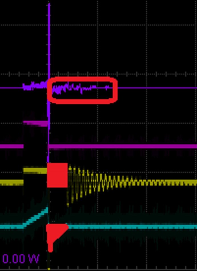
On rare occasions, Sweet saw this effect, called self-oscillation, occur in electric transformers
Ref: http://merlib.org/node/5282
The Answers you seek are right here:
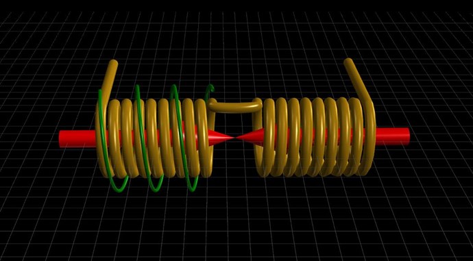
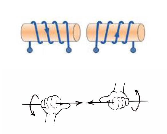
I have provided an entire Thread: Chris's Non-Inductive Coil Experiment and 11 videos on this showing you how to approach this Technology! I have given you all of the data to make this work, and more, to make this, not just a TOY, to make this Power very much more than just a few Globes!
My Friends, when I see 10 successful replications, I will release another Video showing a bit more work, again we have had quite a few successful replications already!
Independent Replication is Scientific Proof:
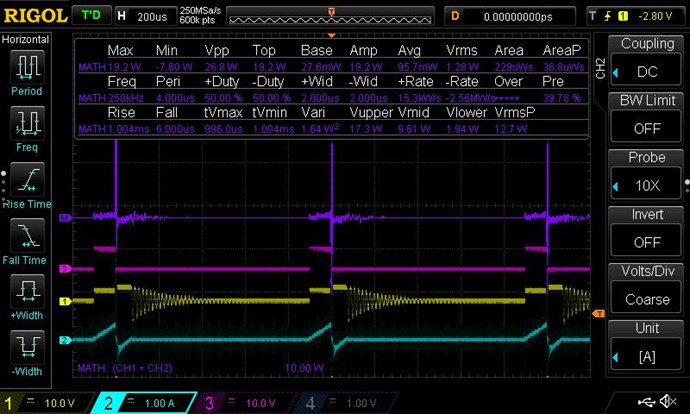
Do the Math in these videos! COP > 1.6 in both Machines!
Technically, My Friend Wistiti was the first, but for undisputable numbers, we have to see Tinmans effort.
Tinman was the first: COP = 1.7
Others followed, like Captainloz: COP = 1.9
Hey Chris,
If people watch your videos its all in there. My experiment is proof of that. I was feeling very frustrated for a long time but then I stumbled on to your youtube channel and it inspired me to keep going. I actually have your book from way back, I wish now just stayed with it but I went down the Ruslan and Akula rabbit holes for too long without understand Asymmetry and the re-gauging process. Anyway mate I'm just trying to say you should be proud of yourself. You are doing a great thing here!
Cheers,
Loz
Ref: Captainloz COP = 2.0
COP = ∞
We have Self-Running Machines, Our Flashlight that a Member of AboveUnity.com has achieved:
Others also, some may not want their names used? Security for people is important to me, but eventually, we must do this as a Team and make a Stand!
Others have also achieved Above Unity, Marcel has also shared with you all, freely:
Aboveunity.com is Light Years Ahead of the other Forums!
Lighting up the Darkness!!!
We ARE Truth, its right here:
Start Here → Builders Guide to Aboveunity Machines
You need to focus, and do the experiments, learn what I have given you, and this, once thought impossible technology, will become second nature, like Breathing is!
It is easy, it is cheap and its definitely NOT Magic! There are No Secrets, I have given you Free Energy!
Best Wishes,
Chris


 6.
6.


