Ok, so I've been reading, watching videos, etc, and a couple comments and an answer to my own question. Then I'll share a small experiment that I did. First the question and comment.
The question was, why is the quote by Walt Rosenthal shared so often.
The VTA "likes" to always see a minimum load of 25 watts.
I found my answer here, in the pdf that is given, Guidelines to bucking coils, in this Floyd Sweet update https://www.hyiq.org/Updates/Update?Name=Update%2030-11-14
Long story short, current on the output equals more magnetic field movement in the system, which is what is making the system work in the first place. So a lot of energy machines, with certain coil configurations, especially when speaking of the VTA, will require a minimum amount of magnetic field movement to work properly. So 25 watts is not a magic number necessarily, it was just a magic number for Floyd Sweets machine. However, if we are building similar, we should expect similar.
So, the comment. I had asked Chris if he remembered where he had mentioned, in some post somewhere, about making the output AC by doing....yadda yadda. I could not remember where this was stated. I found it in the thread 3D Printing Bobbins/Formers for Coils.
The question Chris actually proposed, is here
Chris's answer is here
To sum it up, the answer was to have two units operating 180' out of phase. One providing the positive swing, and one providing the negative swing. Which is interesting, because it seems this is exactly what the VTA is if you divide the machine right down the middle.
Which leads to my small experiment.
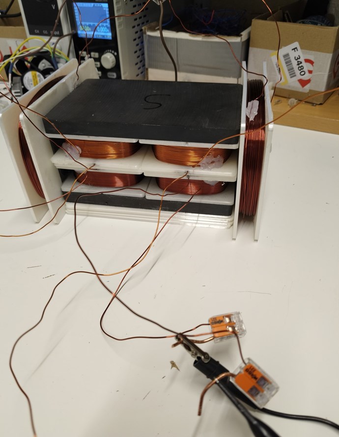
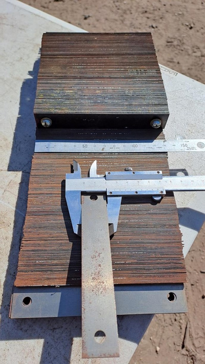
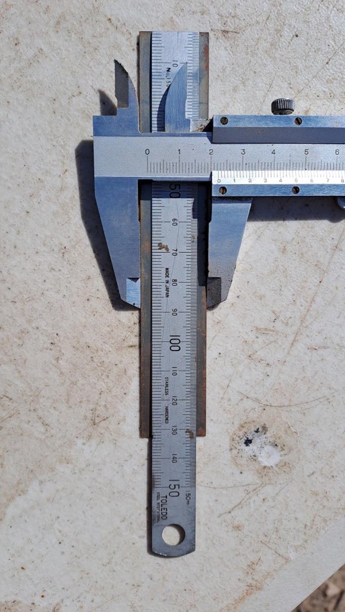
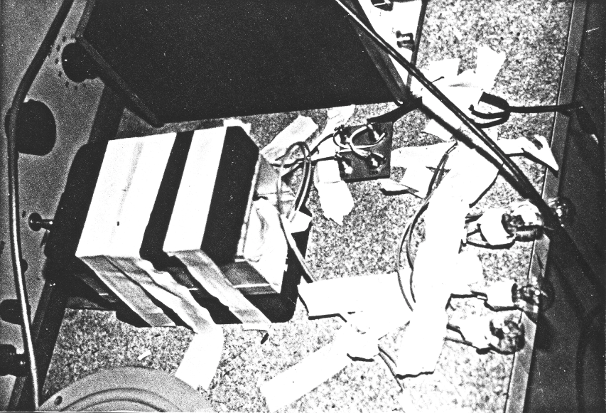
For this experiment I have the four coils, top coils separated from bottom coils with a 3 mm gap. Magnets are present. And two power coils that I'm directly pulsing (pulse, not square wave) and observing the open coil emf on all the four output coils.
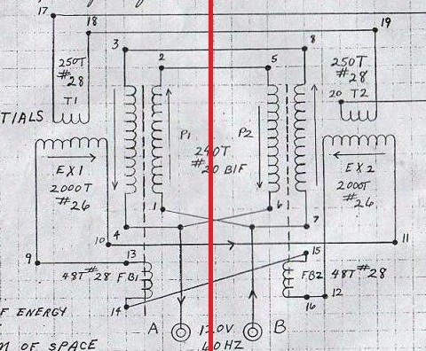
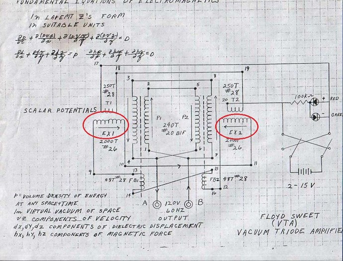
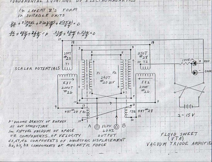
The idea was to see how the coils are responding to the power coils, and to try to get an idea of how the flux is moving in the overall system. The VTA schematic shows the power coils opposing.
Which I thought strange because Walt Rosenthal mentioned they were configured in a push-pull fashion. Here, at about 50 seconds into the video.
So, for the experiment, while observing the open end coil voltages, I tried both opposing and push-pull orientations. Again, with a pulse, not a square wave this time.
This is an example of the output on one coil.
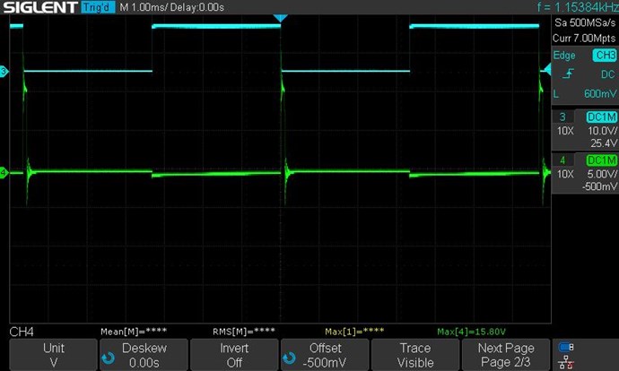
Blue is the input signal, it's 50% duty cycle. Green is the voltage over the coil. We can see that there is a small dip during the on time of the power coils, and then a large positive when the power coils are turned off. If we assume this voltage polarity to be "positive", and test all the coils for the same (not inverted), and use the right hand rule, we get what is in the next picture.
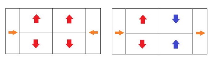
On the left is with the power coils opposing. Assuming "positive polarity" of the coil wave forms, the right hand rule would show all coils would want to have flux outward at the same time. On the right side is with the push-pull configuration. We can see that the POC set on the right side flipped to where the flux would be inward, while the left side is still outward. Again, this is just a pulse, not a square wave. With a square wave push pull configuration we would see the picture of the right alternate, outward/inward -> inward/outward. I flipped the magnets polarity, from both N facing up to both S facing up, but saw no difference. I'm guessing I will once I get appropriate power coils and feedback coils.
Anyway, that is it for now. My wire was delivered today, but I still need to source core material (used microwaves) and design/print the formers for the power coils. I'm sure it will be several days before I get everything done and start experimenting again. Back with more soon!
Thanks!
Marcel


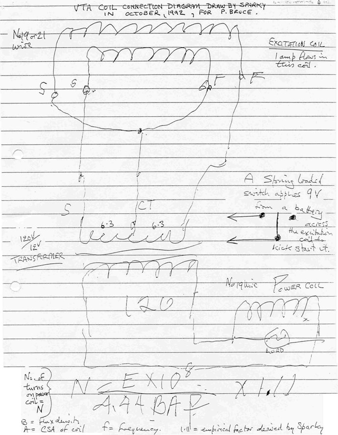


 𝑁 ) required for a transformer winding.


