Fringe look at the A Vector Potential and rotating magnetic fields

  • 956 Views
  • Last Post 07 June 2024
Chris posted this 22 April 2024

On the heels of my Fringe's some coils buck and some coils don't thread, and after a decent amount of reading, videos, and thinking, I'm finding I should probably dive a bit deeper into understanding the A vector potential, with the addition of the rotating magnetic field.

There seem to be a lot of devices which mention a wind up effect, or gyroscopic effect, etc. And a bold assumption of mine, I'm thinking that even the motor or transformer type devices that might not use a rotating magnetic field, work on the same process as those that do use a rotating magnetic field. Maybe they do all have a rotating magnetic field? Time will tell.

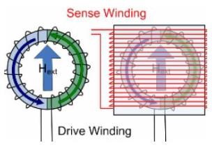
Chris's experiments with the A vector potential A Vector Potential

The same setup with the rotating magnetic field here:


For example Akula has a video here


  • 2:02 He talks about the electromagnetic field swirling.
  • 4:15 He mentions the system automatically adjusts to the load, getting stronger and stronger (building up), and reaches a limit for that given load.
  • 6:10 He connects the bulb and as the voltage goes up, he uses the words "the system accelerates".
  • 6:40 "and so now the acceleration of the magnetic field is underway, rotating it"
  • 8:15 again "...it can spin up this magnetic field…". And other places in the video. Good video, watch the whole thing, with captions on. And also this next one.


Second Akula video, which Chris if I'm not mistaken, this one is not on the AkulaVids list, but this is a good one.


  • 1.31 Talking about the principle of operation "one of the principles that I use in the work of all these devices…". "... by far do not differ from the installation that I did for…" lists different versions, 20W, 1KW, 30KW, etc. All the same principles.

These devices of Akula look exactly like the device of Steven Mark. Especially the second device he shows in this video, where he uses the magnets alone to start it.


I assume everyone has heard Steven Mark talk about the gyroscopic effect, but here he also talks about the wind up/down effect.


  • 2:20 Turns the device on with a magnet alone.
  • 2:50 He states if you remove the magnet the voltage starts to come down, there is a frequency pattern set up and it takes a while to wind down, similar to that of a jet turbine.
  • 3:15 Talks about the device having vibrations, etc.

I have no idea why in the world the device would turn off if you turn it upside down, that doesn't make sense to me, maybe someday it will.

Anyway, I know there are many other inventors that use this same principle. I won't name them all here. I'll probably start with small experiments with the Magnetic Induction Compass, and from there venture on to the rotating magnetic field setup that Chris has on the above mentioned hyiq.org page. And hopefully get a better picture of what is going on in the coils.

Not sure when I'll get started as I might have to order some parts and I have a small trip back to California soon to see family. But this is the direction I'll be heading with experiments. At some point I'll pick at the YoElMiCrO and Akula stuff, but that will probably be a different thread when I'm done with this one.

If I'm heading off in the wrong direction please let me know before I start winding coils! 😁

Back soon, hopefully, with something to share!

Marcel

  • Liked by
  • Augenblick
  • ISLab
Order By: Standard | Newest | Votes
Chris posted this 22 April 2024

Hey Marcel,

My Friend, I totally agree! The Magnetic A Vector Potential is best described by the famous Sir Richard Feynman:


A video I did sometime back:


Here is the PDF of Sir Richard Feynman's lecture on The A Vector Potential.

NOTE: I have shared these items 100% for educational purposes, so don't try to throw another copyright at me you mongrels.

Best Wishes,

   Chris

Chris posted this 22 April 2024

Fluxgate magnetometer experiment

Chris, thanks for the links! A very good video. And I'm not sure what it is about Feynman, but he is really easy to listen to, even with complex subjects. Maybe it's that New York charisma? 😎

So this first experiment, the fluxgate magnetometer, is one of a few I plan to do, just to get myself more familiar with the dynamics of how electromagnetic waves move in the coils.

Here is Chris's original video of the experiment.


This is of course not meant to be above unity, but has several interesting effects going on that I think one could pursue in the case of breaking the unity boundary. And it's been mentioned in documentation of several of the greats before. But first, I'll give my understanding of how the fluxgate works, for those that have no idea. As always, please correct me where I'm wrong, for my benefit as well as others.

Consider the following picture. Credit to www.imperial.ac.uk, linked to the page from which I got the information and the picture. It's an easy read for understanding.

They say in the article that it's better to think about the toroidal core as two halves.


The external magnetic field, in our case it's the magnets, is pulled into the core in one direction. As the drive coil is fired up it produces a magnetic field in the core. In one half of the core it is additive to the magnets field. And in the other half is opposing, and subtractive, of the magnets field. 

As the current in the drive coil rises, the half that is additive will go into saturation first. The magnets magnetic field on that side is "gated" out of the core and creates a voltage/current in the sensing coil. As the drive current continues to rise, the other side of the core eventually saturates too, and the magnets magnetic field is "gated" out trying to create a voltage/current in the sensing coil which is in opposition to the first, so the sensing coil current slows, stops, and starts to fall.

As the current in the drive coil starts to slow the side which came into saturation second, is the first to fall out of saturation, at the same time creating a voltage/current in the sensing coil in the opposite direction. Then the side which was first to go into saturation falls out of saturation as well, creating a voltage/current that opposes the other and the current in the sensing coil slows and stops.

As the current in the drive coil crosses the 0 axis for the second half of the sine wave cycle, the process starts over for the core and sensing coil. Which actually creates an output frequency which is twice that of the input.

So, that was a mouthful. I'll show a scope shot of what I had going on, with the drive coil current starting at the 0 line, for ease of understanding. Also, I'm not sure why this is not as symmetrical as one would assume. Maybe because of the lag, or difference, in the BH curve for saturation and desaturation? But the scope shot here should follow basically what I described above. Totally not sure if I have my lines in the correct spots, but I tried to break it up into the different steps. Again, one half of the drive coil cycle (yellow trace) being on complete cycle of the sensing coil (blue and purple traces)

  • Green trace, drive coil voltage.
  • Yellow trace, drive coil current.
  • Blue trace, sensing coil voltage.
  • Purple trace, sensing coil current.


Here is a video of the effects I saw that were in the original video from Chris.


So, takeaways from the experiment.

  • Big disconnection between the output and the input. Something most researchers I think are looking for? Needs further investigation. If this condition can be brought about with little to no input, then the unity boundary could be easily broken.
  • Saturation is known to create harmonics, as far up as into the radio frequencies. Good substitution for the spark gap, to get those electrons moving?
  • Otherwise, this has been a great brain exercise for understanding saturation, the BH curve, moving fields, and I'm sure more to come after a bit more thinking on the back porch.

So what does this have to do with the A Vector potential? Feynman said the A Vector exists with a motional magnetic field, whether there is a wire there or not. As the core goes into saturation, that is exactly what we are seeing. The pressure of the A Vector potential, brought about by the gated field of the magnet, being applied to the sensing coil. And in the latter part of my video I use the bucking/opposing coils. There is no saturation. There are two magnetic fields canceling, and the electric field doubling. Which to my understanding is two A Vector potentials, canceling in spin, "surging electric field" as Floyd Sweet and Tom Bearden would put it, which is running the sensing coil.

Anything I'm missing?

The next experiment will be Self-Assisted A Vector Potential Oscillation

However, I need to order a few things, and I have a trip to California coming up soon. I'm sure I'll be online reading, commenting, etc, but my bench time is [NULL] for a few weeks at least.

Hope others are getting in some bench time!

Marcel

FringeIdeas posted this 10 May 2024

Super minor update, just to show I'm still here.

California trip went well, tacos and palm trees everywhere. And now starting to get new parts in the mail.

So here are a few new cores I had ordered. I got my measurements a bit off, and the magnets don't fit as well as I thought. I'll try to just fill the gap with something, or order some new magnets.

Still waiting on a 3D printer as well. Wasted too much money on ordering 3D printed bobbins, so I decided to just do it myself. Spent about 200e on a Ender-3 V3. Should arrive soon, let's see. Then I need to learn Blender

Anyway, just checking in. Experiments and hopefully exciting things to share soon.

Marcel


Chris posted this 12 May 2024

Hey Marcel,

As always, good to see progress My Friend!

Floyd Sweet said:

Copper or Cu I2R losses remain but may be minimized by using wire of larger than usual cross-sectional area.


So, the idea, having a larger Core Cross Sectional Area and thus less turns of thicker, or smaller AWG, gives us a better Output.

I have run through some calculations here, and we saw some big improvements.

Hope this helps!

Best Wishes,

   Chris

FringeIdeas posted this 12 May 2024

Hey Chris,

Yes I'm aware that the CSA on the core in the picture leaves much to be desired. I have other new cores as well that have very good cross sectional areas. But for this specific experiment I was aiming a bit more at area to work with. Number of coils, magnet placement, etc. And the options with Mouser were a bit limited. So hopefully it serves the purpose of the experiment and I can learn something.

I do appreciate the pointers, thanks!

Marcel

Plasmonic posted this 14 May 2024

Hey Marcel,

Just a little help I can possibly offer to you at the moment.  I wouldn't use Blender for designing parts/tools.  It can be done and maybe easier than I understand.  But, I really think you would find more benefit from using something like FreeCAD or Fusion 360 ( FreeCAD is actually free and you don't need any account or login just download, install, and make parts ).

Lots of tutorials available, I'd recommend using the Part Design Workbench.  The regular Part Workbench can work too.

Maybe look for Joko Engineering on youtube and look for his FreeCAD videos.

Be well,

Matt

FringeIdeas posted this 14 May 2024

@Plasmonic

You could not have told me that a bit earlier? 😂 Kidding. I did spend all day today learning Blender basics and modeling a former for the experiment, more of a test  Iguess. I will actually use 2 of these U and I cores, so the CSA will be a bit better. I came up with this.

Will it print! We shall see in the morning. Two of those should snap together niceley to make one former. But, there are a few areas where the parts of the object are not exactly lined up. How they got off, I have no idea. Good learning experience.

I will however checkout FreeCAD though like you suggest. I'm not looking to model mideval characters and whatnot, so it sounds like FreeCAD might be a better option. I do appreciate the tip!

Marcel

FringeIdeas posted this 15 May 2024

@Plasmonic you saved me.. 

I tried slicing and printing my Blender design, and it was a complete disaster. So I spent all day trying to fix things, importing into other programs to try to fix things, nothing worked. Finally gave up and installed FreeCAD.

Spent a few hours learning FreeCAD basics, and came up with a good design. It was SO much easier. I think there is a way to create gcode files from FreeCAD, but I ended up just exporting STL files and slicing them in PrusaSlicer with some premade configuration files I found for the Ender 3 V3. After a few heat and speed adjustments, this is what I ended up with.

Two pieces, snapping together very nice. The length of the coil (from top to bottom in the picture) is wrong, it's a bit too much, so I need to adjust. But they printed beautifully! So I need to adjust the length a bit and print four complete sets. Not sure if I can get to it this week or weekend. I have a sick kid staying home from daycare that I need to help watch. But soon. I'll print what I need and get some copper on them. Then finally back to some experiments.

Anyway, much closer now, and I really appreciate the FreeCAD tip, that was a lifesaver!

Marcel

Plasmonic posted this 16 May 2024

Hey Marcel,

 Happy to help!  You picked up on it faster than I did, and did an excellent job, good work!

You're correct about it being able to make gcode but last I knew it only supports gcode and parameter control for milling and maybe its compatible with a laser cutter.  If you have a CNC router or laser you'll probably find the toolpath/gcode creation in it a nice tool though.  It was a bit buggy last time I was using it, but it's recently been getting some very big updates.

Long story short.  You did the right thing exporting the model and using a slicer.

You'll find that with the parametric control you'll make exactly what you want with some usually very quick and easy changes.

Enjoy your new superpower, and hats off to you on the excellent work!

Be Well,

Matt

FringeIdeas posted this 16 May 2024

@Plasmonic thank you! I appreciate the kind words.

The gcode from FreeCAD, I was getting the same feeling, that it was just for CNC type stuff. That is why I figured I would just try the slicer. It worked out quite well though, so thanks again for the information.

And yes, I'm enjoying the superpower It's been fun getting into the 3D printing world.

So after a few more little tweeks, I managed to get my formers.

Tomorrow  I will add a little glue, and prepare them for winding. Over the weekend I think I'll be able to get some copper on them. And next week start messing around with experiments. 

So again I appreciate the help, you took a lot of the pain away

I'll get back soon with some experiment results.

Much appreciated,

Marcel

FringeIdeas posted this 22 May 2024

Hey,

Quick and dirty post here, because I've been messing around with coils all day and have not really got any day job work done.

This is a reproduction of this video, which is part of a study on the A Vector Potential.


So I got the coils wound and found an extra magnet to fill the gap at the top of the stack of magnets. I also used two of the UI cores side by side to increase the CSA to 28mm x 40mm. Still not much, but it seemed to work out.

Here is a picture of the setup.

Sin wave input at 200 Hz driving my audio amplifier into the bottom left coil. Output coil on the bottom right which had the 12v 300mA bulb attached to it. A vector potential coils on top. All coils are 175 turns of 0.8mm wire, 1.9 Ω, 4.22 mH.

The A vector potential coils were cc/ccw. Shorted in this way..

In this configuration of coils it was easy with the eyes to notice the bulb get brighter when shorting the A vector potential coils, not so easy to see on the camera.

The magnets didn't seem to make any difference for me. Probably just how the setup is being used, I'm not sure, maybe I did something wrong. I ended up just taking them out and experimenting without them.

I then moved the A vector potential coils away from each other. One being closer to the input coil and one being closer to the output coil. And the effect became much better.

So a quick assumption would be that the input coil is interacting with the left A vector potential coil, while also interacting with the output coil, the two closest coils. Then the resulting fields from those coils interact with the A vector potential coil on the right. Which would makes sense in how the currents are running in the A vector potential coils, once one fumbles through the right hand grip rule a few times for each coil.

Here is a video where I go through all the same information, a little bit more detail, etc.


This opened up so much more to think about. The interactions of four coils together on a core is a bit daunting. But lots to think about here. It is obvious though that the shorted pair of bucking coils does in-fact increase the output, with a little input gain. But I think overall what we are seeing is an increase in the effective magnetic fields, moving in time, creating a larger or more effective A vector potential to interact with the output.

Questions and comments are welcome. I'll be playing with this one for a while. Again, lots to think about.

Thanks!

Marcel

FringeIdeas posted this 22 May 2024

Edit: Typo, the coils each have 275 turns, not 175 turns.

FringeIdeas posted this 01 June 2024

Hey Chris,

While I'm still messing around a bit with this last experiment, I'm trying to gear up a bit for the next. The video where you show the compass spinning, the rotating magnetic field.

Anyway, I've been meaning to ask, do you still wind your coils by hand, or have you got some kind of winding rig? I think out of all the pictures and videos you have shared I've seen maybe only one crossover. I'm getting better over time with winding, but of course as my experiments continue i'm putting more importance on the symmetry of the POC coils.

For example, some on the forum, including myself, have noticed while performing the open end resonance tests there are differing results depending on which side the coils are pulsed from or observed from. I'm sure some of this is the dynamics of the magnetic field traversing the coils. But I'm also sure that part of this is because of the differences in wire lengths, inter-wind capacitance, inductance, etc.

So yeah, still winding by hand, or have you built a winding rig?

Thanks!

Marcel

Chris posted this 01 June 2024

Hey Marcel,

Yes, I have built a Winding Rig, with a budget counter, its crude, but it works:


Which does make winding Coils like this:


The Shaft with Bearings on it, its from an old Washing Machine:


Makes sense to Re-Use when possible!

When I was a kid, we messed around with old AM Radios, and we used to wind coils and so on, I used to be amazed by the Coils structure and uniformity, the turns and how they sit so neatly, side by side, and the helical structure, I was fascinated by its beauty and elegance, such a simple structure doing so many magical things - The Magnetic Field is like Magic if one stops and thinks about what it does.

Anyway, enough rambling from me.

I hope this helps in your winding of coils! Even if its crude and somewhat antiquated looking.

Best Wishes,

   Chris

FringeIdeas posted this 02 June 2024

Hey, very nice, thanks for the pictures!

And good rambling, I understand the feelings. I can hand wind almost perfect up until about layer 4 and the coils are just beautiful. Then after that it just becomes chaos and I start to lose interest.

I'll see what kind of parts I can find around here that would make a good rig.

Thanks again, it's appreciated!

Marcel

FringeIdeas posted this 02 June 2024

Regarding my last experiment, the more I go over the results I realize I somehow comletely botched the experiment. I'll quickly explain.

Hyiq.org page on the experiment here A Vector Potential

Which contains this pdf link of a deeper look at the experiment. Self Assisted A Vector Potential Oscillation 

Basically, understanding how bucking coils are supposed to work, they really should not have had any excitation from the input coil, simply because the coils are CW/CCW. Mine seemed to. 

Also, in my setup, the magnets had no effect. If they were there or not it made no difference. And that just doesn't make sense. Here is an interesting video, which I thought was somewhere on this forum but I couldn't find it, so I just clicked on YouTube until I did.

The main point to be taken is the flux from the magnet can be switched from side to side. The flux being switched means a magnetic field in motion = A Vector potential. So I should have seen some kind of effect. If I'm correct, as the flux from the magnet switches from one side to the other, it does induce voltages/currents in the correct polarities in the A Vector coils.

Anyway, I need to figure out what went wrong. Which is why I was asking about the coil winding rig I might decide to make new coils, not sure yet.

Back to the porch to do some thinking. A revisit of this experiment is coming, hopefully soon.

Marcel


Chris posted this 02 June 2024

Hey Marcel,

Yes, you're right, in what you say!

PLEASE don't get bogged down in the area of Magnets, you don't need Magnets to make this work! Magnets are a Distraction! I say this for others, I see you have already experienced this.

However, I don't think you 'botched' the experiment, I think you did a good job! Sorry, lack of time, I have now caught up!


At 7 minutes approx, look at the Input Current! So you have it all spot on! Adjust your Frequency, until you see the shorting and un-shorting of the Coils make no difference on the Input, this is Magnetic Resonance.

If POCOne and POCTwo are equal and opposite, and the Input Coil has a Coupling factor of 1.0 to both POC, then mathematically, we get a Vector Equation of: POCOne + POCTwo = Zero

So each POC, because the Magnetic Fields Cancel, they have no Reflection back on your Input Coil. Your Input drops, and can go to Negative, if enough power is reflected back to your Input, so as Don Smith said, the Battery can charge if you have enough power going back to the Input.

I showed this here, 12 Years ago:


You can hear this in Tinmans RTV3 Video, and others you can observe this:


Note: The Torque section.

The Key is, POCOne and POCTwo mush have approximately the same Current, Equal and Opposite, Magnetic Resonance for this to work (Referenced as Tuning):


I hope this helps!

Best Wishes,

   Chris

FringeIdeas posted this 03 June 2024

Hey, ok nice to hear thank you!

I'll keep playing with this a bit more before moving on. It's interesting for sure. I'm tripping up a little on visualizing how the POC coils can be not reflecting back onto the input, yet at the same time aiding the output in some way. And I mean just the movement of the fields through the core, the interactions.

I'll get it though. Just a bit more bench and porch time and I'll start prepping for the next experiment.

I do appreciate the feedback and the links!

Thanks again!

Marcel

Chris posted this 03 June 2024

Hey Marcel,

If I may offer some advice?

It is perfectly normal to have questions and actually doubt yourself, or your work, I have been through the exact same stage, with a lot of doubt and feelings of confusion and doubt in general. Its normal, but, it will pass.

You are a very good researcher!

Understanding the Coupling of Coils, for example in the Flux Gate Magnetometer:


Is an important step forward. Because the way the Coils are wound and they Currents in the Coils flow, the Input Coil has a decoupling from the Output Coils, because exactly half of the Coupling is Opposite to the other half.

The big problem with the Flux Gate Magnetometer is the total opposition of the Magnetic Field, you need 100% Plus opposition, to over come the Magnets Flux and Reluctance. This can be very expensive on your Input, but its a very good experiment to do, because there is a lot to be learnt.

I am very pleased to have you here with us! Thank You My Friend, I appreciate your friendship and collaboration here! Its lots of fun having good people here to work with!

Best Wishes,

   Chris

FringeIdeas posted this 03 June 2024

Hey, advice is always welcome.

The decoupling of the input coil from the bucking coils (or output coils in the example of the flux gate) due to the way they are wound makes sense. When they are equal and opposite there is nothing to reflect back onto the input. But then visualizing the A Vector is still a bit confusing.

For example, it has spin. But when the magnetic fields from the bucking coils meet, Φ cancels, A doubles, does the A still have spin or does the spin cancel. I'm sure I heard Bearden say the spin cancels, but is there still some kind of push in some direction? I'm wondering this, for example, because of the video where you show a rotating magnetic field. 

Which I have got working to some extent actually, just playing around, I just was not ready to get too deep into it yet.

But the rotating magnetic field to me would say there is still some kind of directional movement of vector A… OR like Bearden says it's a "pulsating electric field", which influences the other coils to create this rotation of magnetic field.

Anyway, just thinking out loud a bit here, still plenty to go over. I'll keep poking at this one experiment before I move on to that rotating magnetic field. And maybe give the magnetic flux gate experiment another once-over, it's still sitting on my desk.

Thank you as always and I appreciate the kind words! This continues to be a fantastic journey, I do appreciate the effort you have put in to share all this information and experiments to reproduce, it helps a lot. And I'm of course happy to share and help out where I can.

Marcel

Chris posted this 03 June 2024

Hey Marcel,

Richard Feynman said: There is an Electric Field present only when there is a Changing Magnetic Field

So, if Phi is not Changing, there is no A Field, this is my experience, and is fairly easy to verify.


I hope this helps.

Best Wishes,

   Chris

FringeIdeas posted this 04 June 2024

Hey, I think maybe my use of the word "cancel" in regards to Φ was possibly a bad choice.

I was just meaning superposition of the magnetic fields from the bucking coils.

Also, I think one improvement I could make for this experiment is more power. There is this video which was put out a little after the others.


And in the pdf Self Assisted A Vector Potential Oscillation you mention..

It’s interesting to note that I needed 15.2 Watts to get this effect to become visible. Walt Rosenthal said the VTA liked
to see 25 Watts.

Granted I did see a tiny bit of the effect, I am still only measuring about 2.4 W on the input coil and about 1.7 W on the output coil over the bulb. So maybe attempting this again with a bit more juice would help bring out the effect. I'll try and give that a go.

Thank you again for the guidance!

Marcel

Gucio posted this 07 June 2024

@Plasmonic

You could not have told me that a bit earlier? 😂 Kidding. I did spend all day today learning Blender basics and modeling a former for the experiment, more of a test  Iguess. I will actually use 2 of these U and I cores, so the CSA will be a bit better. I came up with this.

Will it print! We shall see in the morning. Two of those should snap together niceley to make one former. But, there are a few areas where the parts of the object are not exactly lined up. How they got off, I have no idea. Good learning experience.

Hey Marcel. I use "Tinkercad" to design simple 3D figures. It works in the browser, is simple, intuitive and free. There are lots of tutorials on YouTube. For our purposes, i.e. spools for coils etc. nothing could be simpler. I really recommend.

Examples of my prototypes


For our purposes, the simplest 3D program. I really recommend "Tinkercad"


Grzegorz

FringeIdeas posted this 07 June 2024

Oh wow nice work! I might check that out. FreeCAD seems to be working for now, but i'm always game for something a bit more comfortable if it prooves to be.

Thanks, I appreciate it!

Marcel

We're Light Years Ahead!
Members Online:

No one online at the moment


What is a Scalar:

In physics, scalars are physical quantities that are unaffected by changes to a vector space basis. Scalars are often accompanied by units of measurement, as in "10 cm". Examples of scalar quantities are mass, distance, charge, volume, time, speed, and the magnitude of physical vectors in general.

You need to forget the Non-Sense that some spout with out knowing the actual Definition of the word Scalar! Some people talk absolute Bull Sh*t!

The pressure P in the formula P = pgh, pgh is a scalar that tells you the amount of this squashing force per unit area in a fluid.

A Scalar, having both direction and magnitude, can be anything! The Magnetic Field, a Charge moving, yet some Numb Nuts think it means Magic Science!

Message from God:

Hello my children. This is Yahweh, the one true Lord. You have found creation's secret. Now share it peacefully with the world.

Ref: Message from God written inside the Human Genome

God be in my head, and in my thinking.

God be in my eyes, and in my looking.

God be in my mouth, and in my speaking.

Oh, God be in my heart, and in my understanding.

We love and trust in our Lord, Jesus Christ of Nazareth!

Your Support:

More than anything else, your contributions to this forum are most important! We are trying to actively get all visitors involved, but we do only have a few main contributors, which are very much appreciated! If you would like to see more pages with more detailed experiments and answers, perhaps a contribution of another type maybe possible:

PayPal De-Platformed me!

They REFUSE to tell me why!

We now use Wise!

Donate
Use E-Mail: Chris at aboveunity.com

The content I am sharing is not only unique, but is changing the world as we know it! Please Support Us!

Thank You So Much!

Weeks High Earners:
The great Nikola Tesla:

Ere many generations pass, our machinery will be driven by a power obtainable at any point of the universe. This idea is not novel. Men have been led to it long ago by instinct or reason. It has been expressed in many ways, and in many places, in the history of old and new. We find it in the delightful myth of Antheus, who drives power from the earth; we find it among the subtle speculations of one of your splendid mathematicians, and in many hints and statements of thinkers of the present time. Throughout space there is energy. Is this energy static or kinetic? If static, our hopes are in vain; if kinetic - and this we know it is for certain - then it is a mere question of time when men will succeed in attaching their machinery to the very wheelwork of nature.

Experiments With Alternate Currents Of High Potential And High Frequency (February 1892).

Close